

Page 1

Shut Height Monitor with Resolver/LDT Interface
Installation and Programming Manual
Series 2110
GEMCO
Shut Height Monitor
®
Page 2

ii
1080 North Crooks Road
Clawson, MI 48017-1097
Phone: (248) 435-0700
FAX: (248) 435-8120
Internet: www.ametekapt.com
www.ametek.com
This manual is divided into three parts. Part 1 provides an introduction and installation
instructions for Series 2110 Shut Height Monitor. Part 2 contains instructions for the basic
operation and programming of the monitor. Part 3 contains four appendixes: Error Messages,
Function Summary Chart, Catalog Numbering System, and Specications. A glossary and index
are also provided at the back of this manual.
Disconnect power before servicing. The Gemco Series 2110 contains no servicable components
other than the power supply fuse. Consult factory for repair or replacement.
Copyright 1997, 1998, 1999 by AMETEK, Inc.
All Rights Reserved - Made in the U.S.A.
Version 0.3
Ametek has checked the accuracy of this manual at the time it was printed. Any comments you
may have for the improvement of this manual are welcomed.
Ametek reserves the right to revise and redistribute the entire contents or selected pages of this
manual. All rights to the contents of this manual are reserved by Ametek.
Preface
Page 3

Installation, Maintenance, and Programming Manualii
iiiInstallation, Maintenance, and Programming Manual
ii
Contents
Chapter 1: Theory of Operation ..........................................................................1
Chapter 2: Hardware Overview
2.1: Standard Modules ........................................................................................................... 2
Controller (FMMP01) ..................................................................................................... 3
Relay Output (FMOR01) ............................................................................................... 3
Digital Output ................................................................................................................. 3
Power Supply (FMPS01) ............................................................................................... 3
2.2 Input Module................................................................................................................... 4
Resolver (FMIR01) ........................................................................................................ 4
Variable Pulse (FMIP01) ............................................................................................... 4
LDT Input (FMIP02) ...................................................................................................... 4
2.3 Status LED's/Programming Keys ................................................................................... 5
Chapter 3: Mounting and Wiring ........................................................................7
Things to Consider ......................................................................................................... 7
3.1: Mounting & Section ...................................................................................................... 7
Controller ........................................................................................................................ 7
Resolver .......................................................................................................................... 8
LDT ................................................................................................................................ 8
Cabling V1 Option .......................................................................................................... 8
3.2: Wiring.............................................................................................................................. 11
Controller Module (FMMP01) ....................................................................................... 11
Relay Output Module (FMMP01) .................................................................................. 11
Power Supply Module (FMPS01)................................................................................... 12
Resolver Module (FMIR01) ........................................................................................... 13
Variable Pulse LDT Module (FMIP01) Input Option V1............................................... 13
LDT Input (FM1P02) Input Option L1 ......................................................................... 14
Chapter 4: Programming ..................................................................................... 18
Before Getting Started ....................................................................................................18
Programming Keys Dened ........................................................................................... 19
4.1: Resolver Conguration Functions .................................................................................. 20
Scale Factor (300) ...........................................................................................................20
Turns Counting (301) ..................................................................................................... 21
Position Offset (302) ......................................................................................................21
Conguring the Resolver ...............................................................................................21
Enter Scale Factor for the Conguration Process ..........................................................22
Set Turns Counting to 1 .................................................................................................22
Set the Position Offset to 0 .............................................................................................23
Enter Newly Determined Scale Factor ...........................................................................23
Page 4

iiiInstallation, Maintenance, and Programming Manualiii
Adjust the Turns Counting Factor ..................................................................................23
4.2: LDT Conguration Function .......................................................................................... 24
Wire Speed (300) ...........................................................................................................24
Count Direction (301) ....................................................................................................26
Position Offset (302) ......................................................................................................27
Zero Pulse Time (305) ....................................................................................................27
Fault Pulse Time (306) ...................................................................................................28
LDT Output Type (307) .................................................................................................28
4.3: Monitor Setup Functions ................................................................................................29
Unit of Measurement (14) .............................................................................................. 29
Decimal Location (13) ...................................................................................................30
Position Hold (15) ..........................................................................................................30
Auxiliary LED (16) ........................................................................................................31
4.4: Press Setup Functions ....................................................................................................32
Move Detection Time-Out (12) ......................................................................................32
Bolster Offset (303) ........................................................................................................33
Negative Over Travel Limit (304) .................................................................................33
Upper End Limit (400) ...................................................................................................34
Lower End Limit (401) ..................................................................................................34
Relay State (402) ............................................................................................................35
Relay Override (403) ......................................................................................................35
4.5: Digitial Outputs .............................................................................................................. 36
Output Type (200) ..........................................................................................................36
Latch/Synchronize Handshake (201) .............................................................................37
Logic Level (202) ...........................................................................................................37
Error Condition Output State (203) ................................................................................38
4.6: Program and Supervisory Mode Functions ....................................................................41
Program Mode Access (10) ............................................................................................41
Program Mode TIme-Out (11) .......................................................................................42
Appendix A: Error Messages.............................................................................. 43
Error Conditions (306) ...................................................................................................48
Appendix B: Function Summary Chart ........................................................... 49
Appendix C: Catalog Numbering System ......................................................... 51
Appendix D: Specications ................................................................................. 52
Glossary ..........................................................................................................................53
Index ...............................................................................................................................55
Page 5

1
Installation and Programming Manual
Chapter 1: Theory of Operation
Chapter 1: Theory of Operation
The Series 2110 shut height monitor accurately indicates shut height positions to quickly and
accurately assist setup personnel in changing a die on a mechanical stamping press. Positions
can be monitored within a thousandth of an inch. During a die change, the monitor displays the
position of the press’s shut height on a large LED display. If the shut height is moved beyond
its programmed end limits, the monitor de-energizes a limit switch. (This will only occur if the
optional relay module is installed.) This limit switch can work in conjunction with the safety
interlock of the press. For example, when wired properly, power will be removed from the
press’s ram adjust motor(s).
The monitor can also stop updating the shut height during a press’s stamping cycle while
retaining the last shut height read. This is used to lter out press movement and deection
during the stamping cycles. When power is applied to the input, the monitor holds the displayed
shut height on the read out. When this input is released, the monitor continuously updates the
display with the current shut height position.
A built-in timer is also included which is used to detect a possible jam or drive component
failure. The timer starts when power is applied to the ram adjust motor(s) and stops when the
monitor senses motion from the input device. If the ram does not move within a programmed
value, the monitor de-energizes limit switches and displays an error message. When properly
wired to the safety interlock of the press, the limit switches de-energizing will take power away
from the press’s ram adjust motor(s).
Other features of the shut height monitor include the following:
n Measures in inches or millimeters.
n Program mode access code protects against unauthorized access.
n Separate bolster plate offset speeds setup.
n States of the limit switches can be changed for N.O. and N.C.
operations.
Page 6
Installation and Programming Manual
2
Chapter 2: Hardware Overview
3
Installation and Programming Manual
Chapter 2: Hardware Overview
Chapter 2: Hardware Overview
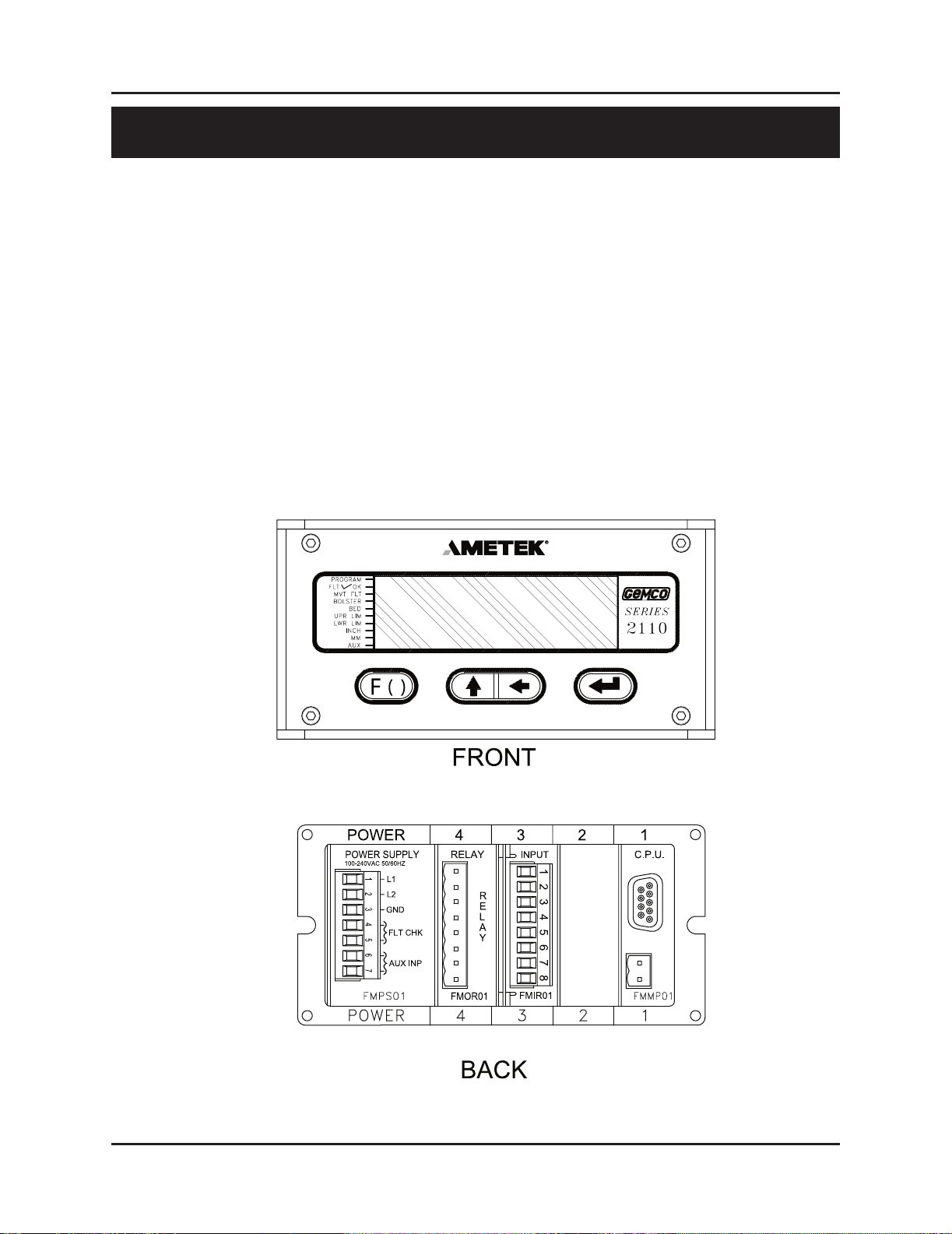
The shut height monitor contains a heavy-duty case which can hold up to ve modules:
n Power Supply
n Controller (CPU)
n Digital Output (optional)
n Analog Output (optional)
n Resolver Input (optional)
n Linear Displacement Transducer L1 (optional)
n Linear Displacement Transducer V1 (optional)
n Relay Output (optional)
The shut height monitor’s faceplate contains a 6-digit, seven-segment LED display and four
programming keys. The LED display is used to indicate the shut height position as well as to
enter parameters when programming. The programming keys are used to program the monitor.
Ten small status LEDs are also provided. These LEDs are used to indicate the state of the
monitor during machine operation.
Figure 2-1 Shut Height Monitor
Page 7

3
Installation and Programming Manual
Chapter 2: Hardware Overview
This section provides descriptions of the shut height monitor’s standard modules. See also Section
2.2: Input Modules. For wiring instructions, see Section 3.2: Mounting & Wiring.
Controller (FMMP01)
This module contains the Central Processing Unit (CPU) which is used to process data it receives
from the resolver or LDT (depending on which input device is used). It then shows the position
of the shut height on the monitor’s display. The controller is also responsible for continuously
monitoring all programmed setpoints and timing functions. To store programmed functions,
including calibrated settings, the controller contains battery-backed memory. This battery requires
no maintenance and is non-replaceable. The controller is located in slot 1 of the enclosure.
Relay Output (FMOR01)
This is an optional module. It contains an upper and lower limit relay. These relays can be
programmed to either energize or de-energize when the press’s shut height reaches either of the
relay’s programmed limits. When these relays are programmed to de-energize and are wired
properly, power will be taken away from the press’s ram adjust motor(s). For a listing of errors
which will cause the upper and lower limit relays to de-energize, see Chart A-5 in Appendix A:
Error Messages. The relay output module is located in slot 4 of the enclosure.
Power Supply (FMPS01)
This module supplies power to the shut height monitor. It also contains a fault check relay and an
auxiliary input. The fault check relay is designed to take power away from the press’s ram when
a fault occurs during machine operation, or when power is taken away from the monitor. In order
for this to work, the fault check relay must be properly wired to the press’s safety interlock. For a
listing of errors which will cause the fault check relay to open, see Chart A-4 in Appendix A: Error
Messages. The auxiliary input is used with the press’s ram adjust motor(s). When used with the
Move Detection Time-out function, this input can detect a possible jam or drive component failure
when power is applied from the motor(s) but no movement occurs. When used with the Position
Hold function, this input can be used to stop the monitor from updating the shut height during a
press’s stamping cycle. The auxiliary input accepts 85-265 VAC. The power supply is located in
slot 5 of the enclosure.
Digital Output (FMOD01) Output Option D1, D2 or D3
This module is used to transmit parallel digital output data to a PLC or personal computer. The
digital output is eld congurable for position or velocity data in a binary, BCD or grey code
format. This data is updated every 50 microseconds for resolver input and 40 milliseconds for
LDT input. The electrical characteristics of this output data can be current sinking, current
sourcing or TTL, which must be specied in the module’s part number.
2.1: Standard Modules
Page 8

Installation and Programming Manual
4
Chapter 2: Hardware Overview
5
Installation and Programming Manual
Chapter 2: Hardware Overview
This module also provides two input pins for use as a eld congured latch or synchronized
handshake input. The latch input freezes the digital output data while the PLC reads it. The
data is updated when the input is released. When congured for synchronized handshake, the
PLC must provide a clocked square wave input into these input pins. Digital data is updated
on each transition of the square wave and the PLC is synchronized to read the updated position
data after a 100 microsecond settling time.
This input accepts a 5 to 24 VDC source from the PLC to perform the latch or synchronized
handshake function described above. For details on wiring to the digital output board, see
pages 16 & 17.
Analog Output (FMOA01) Output Option A1
This module is used to transmit position or velocity data to a PLC in an analog format. The
module provides two separate analog output channels that can be independently congured for
position or velocity data.
These analog outputs can be eld scaled over any range and congured for 0 - 10 VDC, 10 - 0
VDC, -10 VDC to +10 VDC, 4 - 20 mA, 20 - 4mA, 0 - 20 mA or 20 - 0 mA.
For applications that require remote indication it is recommended to use an aftermarket analog
input display or a digital input display. When using one of these displays the optional analog or
digital output board must be specied in the part number.
The shut height monitor can be used with a resolver or Linear Displacement Transducer (LDT).
Both input devices’ input modules are located in slot 3 of the enclosure. You can identify the
module type by the name found on the back of the module.
Resolver (FMIR01) Input Option R1
This module is used with a Gemco resolver. The resolver assembly consists of a highly
accurate and repeatable brushless resolver, housed in an industrial-grade enclosure. The shaft
position is calculated from two analog signals that vary as a function of the angular rotation of
the input shaft.
The brushless resolver works on the same principle as a rotary transformer to couple power into
the rotor. The construction of the brushless resolver consists of a two-phase stator and a singlephase rotor. Each stator is positioned 90° apart from each other. The two stators continually
provide two different output voltages. Using these two outputs, the module performs a
ratiometric conversion and provides an absolute position. This results in a highly accurate
and repeatable transducer having excellent reliability with an innite resolution which can be
converted by a resolver-to-digital converter into digital position data.
2.2: Input Modules
Page 9
5
Installation and Programming Manual
Chapter 2: Hardware Overview
Variable Pulse (FMIP01) Input Option V1
This module is used with an LDT that provides its output in the form of a pulse width modulated
RS-422 signal. The module only works with Gemco 951VP2110 LDT’s.
LDT Input (FMIP02) Input Option L1
This module will accept an output from a controlled pulse, start stop pulse or variable pulse
magnetostructive LDT. This card accepts a wide range of LDT inputs and faster updates than
the variable pulse described above.
It allows the shut height monitor to receive the signals from the LDT. The pulse width signal
is converted to position data which the monitor displays and uses for shut height position. The
module also provides +24 VDC to supply power to the LDT. The monitor was designed to
work with the Gemco Series 951 or 952 LDT. However, other LDTs can be used with the shut
height monitor. If you are using a different type of LDT, contact the factory for wiring and
programming instructions.
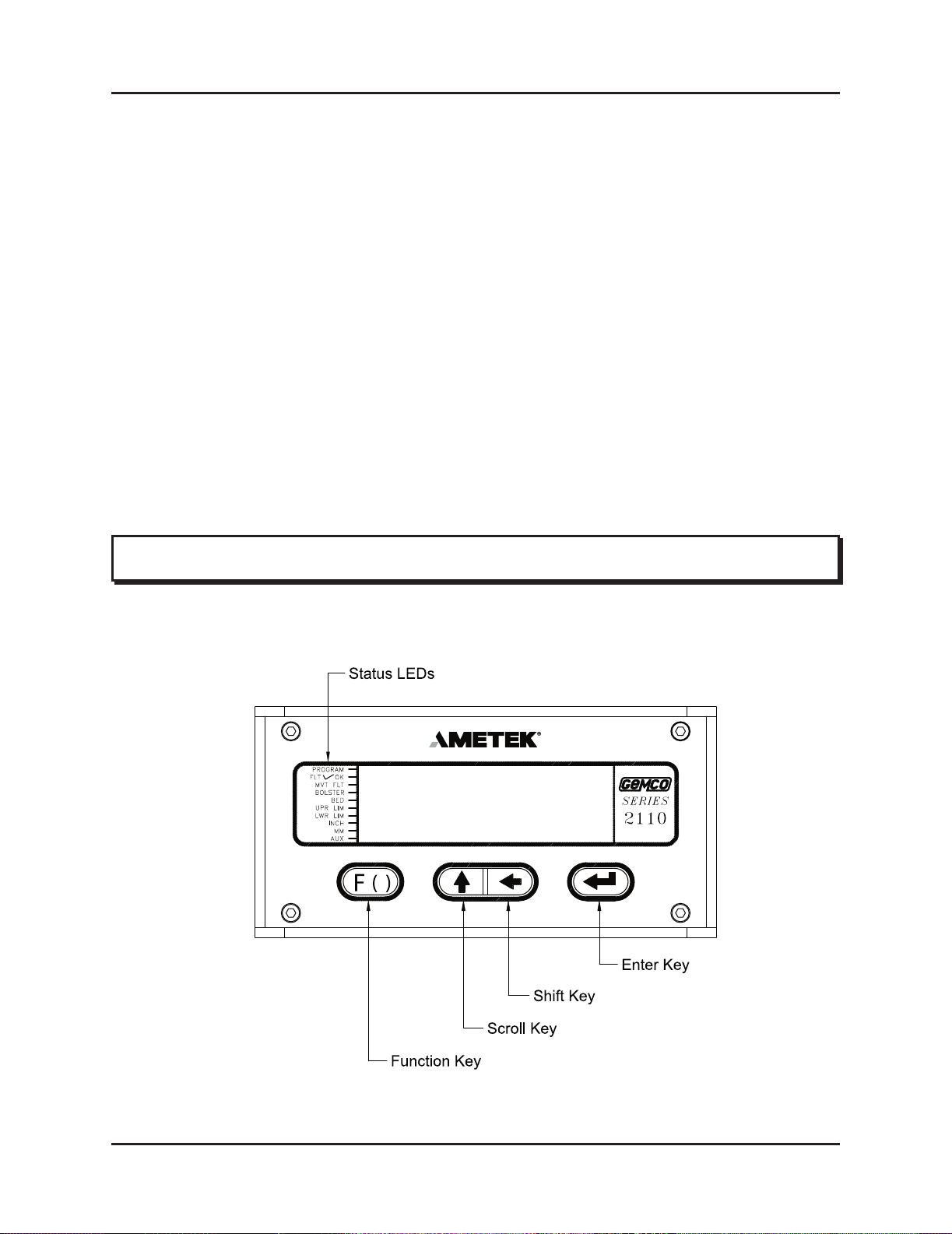
The shut height monitor has 10 status LEDs and four programming keys. The LEDs provide
information on the monitor’s state during machine operation. The programming keys are used
to program functions and perform basic operations.
2.3: Status LED's/Programming Keys
Figure 2-2: Monitor's Status LED's and Programming Keys
Page 10

Installation and Programming Manual
6
Chapter 2: Hardware Overview
7
Installation and Programming Manual
Chapter 2: Hardware Overview
PROGRAM The program LED turns on when the controller is in program mode and
turns off when the controller is not in program mode. Functions cannot be
programmed when this LED is off.
FAULT OK The fault check OK LED turns on when the power supply’s fault check
relay is closed, indicating the system is OK. This LED will turn off when
a fault is detected, indicating that the fault check relay is open.
MVT FLT The movement fault LED turns on when a movement fault is detected.
(For more information, see Move Detection Time-Out in Section 4.4:
Press Setup Functions.)
BOLSTER This LED indicates that the current shut height position is referenced from
a bolster plate. The bolster LED turns on when a value is programmed
into the Bolster Offset function. (For more information, see Bolster Offset
in Section 4.4: Press Setup Functions.)
BED This LED indicates that the shut height position displayed on the monitor
is referenced from the press’s bed. The bed LED turns on when the
Bolster Offset function contains a 0 value. (For more information, see
Bolster Offset in Section 4.4: Press Setup Functions.)
UPR LIM The upper limit LED turns on when the press’s shut height reaches
the value programmed in the Upper End Limit function. (For more
information, see Upper End Limit in Section 4.4: Press Setup Functions.)
LWR LIM The lower limit LED turns on when the press’s shut height reaches
the value programmed in the Lower End Limit function. (For more
information, see Lower End Limit in Section 4.4: Press Setup Functions.)
INCH The inch LED turns on when the unit of measurement is in inches.
MM The millimeter LED turns on when the unit of measurement is in
millimeters.
AUX The auxiliary LED is programmable and can be used with the Position
Hold function. When enabled, this LED indicates when the shut height
position is being held. (For more information, see Position Hold and
Auxiliary LED in Section 4.3: Monitor Setup Functions.)
Page 11

7
Installation and Programming Manual
Chapter 2: Hardware Overview
The function key is used to begin a process for programming a function.
When this key is pressed, the monitor prepares itself for the entry of a
specic function number.
The scroll key is used to scroll through the monitor’s list of function
numbers, as well as other lists. This key is also used to increment selected
digits shown on the monitor’s LED display.
The shift key is used to move to (select) a specic digit shown on the
monitor’s LED display from right to left.
The enter key is selected after a function number has been entered. This
begins the programming process for the selected function. The enter key
is also used to program a value in a function.
NOTE: For more information on how to use the programming keys, see Chapter 4: Programming.
(F)
↵
←
↑
Page 12

Installation and Programming Manual
8
Chapter 3: Mounting and Wiring
9
Installation and Programming Manual
Chapter 3: Mounting and Wiring
Chapter 3: Mounting and Wiring
This chapter provides instructions for mounting and wiring the shut height monitor. These
instructions have been divided into two sections: Section 3.1: Mounting and Section 3.2:
Wiring.
Things to Consider
It is recommended that you consider the following before installing the shut height monitor:
To minimize the effects of electromagnetic interference (EMI), the monitor
should be mounted as far away as possible from motor starters and control
relays.
The monitor should be mounted in an area free of water spray, corrosive gases,
ying chips, or any other foreign matter that could cause damage to the unit.
If the monitor is mounted directly on the press, it should be installed in an area
where shock and vibration will be minimized.
The monitor should be located in an area that is within the temperature and
humidity specications. (See Appendix D: Specications.)
Controller
To assist you in mounting the shut height monitor, refer to Figure 3-1. Perform the following
steps:
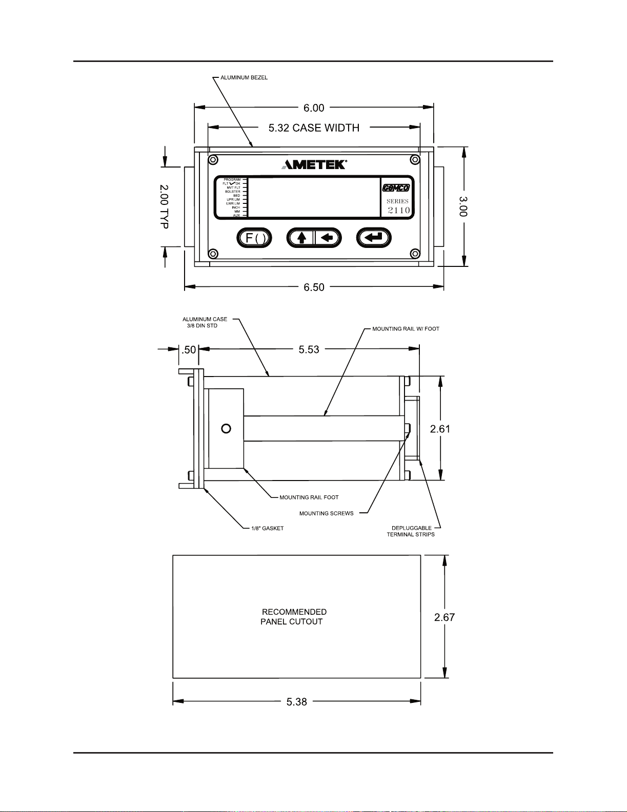
1. According to the dimensions as shown in Figure 3-1, cut out a section of the
panel you wish to mount the monitor to.
2. Remove the mounting rails on the left and right side of the unit by removing
the #6-32 UNC screws located on the rear of the unit.
3. Place the monitor in the newly cutout section of the panel.
4. From behind the panel, insert the two mounting rails into the monitor’s side
grooves. The feet of the rails must be inserted rst. See Figure 3-1 for the
location of the mounting rails.
The mounting rails secure the monitor by their feet being pressed against the
back of the panel.
3.1: Mounting
Page 13

9
Installation and Programming Manual
Chapter 3: Mounting and Wiring
5. Insert each #6-32 UNC screw into each of the monitor’s screw holes.
6. Using a 7/64" Allen wrench, secure the screws into position. This will secure
the mounting rails. Eight to 10 inch pounds of torque is required.
Resolver
The resolver is mounted and coupled to the main ram adjust drive motor, or another shaft that
rotates when the shut height is adjusted.
NOTE: Backlash and slop in the shaft will affect shut height accuracy.
LDT
The LDT is mounted on the upper pitman arm of the press with the sensing rod facing down and
next to the upper ram. The magnet assembly is mounted off the upper ram per the drawing - see
Figure 3-2. Universal mounting kit (SD0441300) will simplify mounting of LDT to the upper
pitman arm. See Figure 3-2A for a typical mounting example.
Cabling
Since the LDT rides with the upper ram, a method must be found to control the cable during a
press cycle.
AMETEK manufactures several cable termination kits which provide a junction box mounted
to the crown of the press and a coiled cord set that protects the cable and its connection to the
junction box and the LDT or resolver. (See Figure 3-2B for general mounting details).
Select the appropriate cable termination kit from the variations listed below.
1) Magnetostrictive LDT used with type V1 input on series 2110 module.
Catalog No. SD0482700L25
2) Magnetostrictive LDT used with type L1 input on series 2110 module.
Catalog No. SD0443800L25
3) Resolver used with type R1 input on series 2110 module.
Catalog No. SD0439600L25
Page 14
Installation and Programming Manual
10
Chapter 3: Mounting and Wiring
11
Installation and Programming Manual
Chapter 3: Mounting and Wiring
Figure 3-1 Dimensional Drawing
Page 15

11
Installation and Programming Manual
Chapter 3: Mounting and Wiring
Figure 3-2 Transducer Mounting
Figure 3-2B Termination Kit
Figure 3-2A Universal Mounting Kit
Page 16
Installation and Programming Manual
12
Chapter 3: Mounting and Wiring
13
Installation and Programming Manual
Chapter 3: Mounting and Wiring
This section contains pinout diagrams for each module. System wiring diagrams follow.
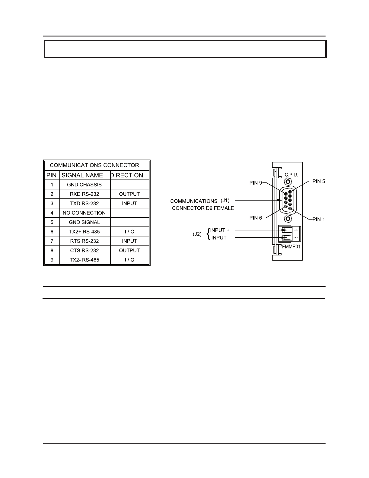
Controller Module (FMMP01)
The controller has two connectors: a D9 connector (J1) for RS-232 and RS-485 serial
communications, and a program lockout connector (J2) intended for a keyswitch. (See Figure
3-3). Making connections to both connectors is optional. However, the program lockout
connector must be jumpered to allow the unit to enter program mode. J2’s input rating is +5
VDC maximum dry contact or open collector (drain) only. Actuation voltage must be less than
+1.0 VDC at 0.2 mA. The terminal wire size is No. 22-12 AWG.
Figure 3-3 Controller Pinout Diagram
NOTE: (J2) program lockout connector.
NOTE: The controller’s program lockout connector (J2) must be jumpered to allow the unit
to enter program mode.
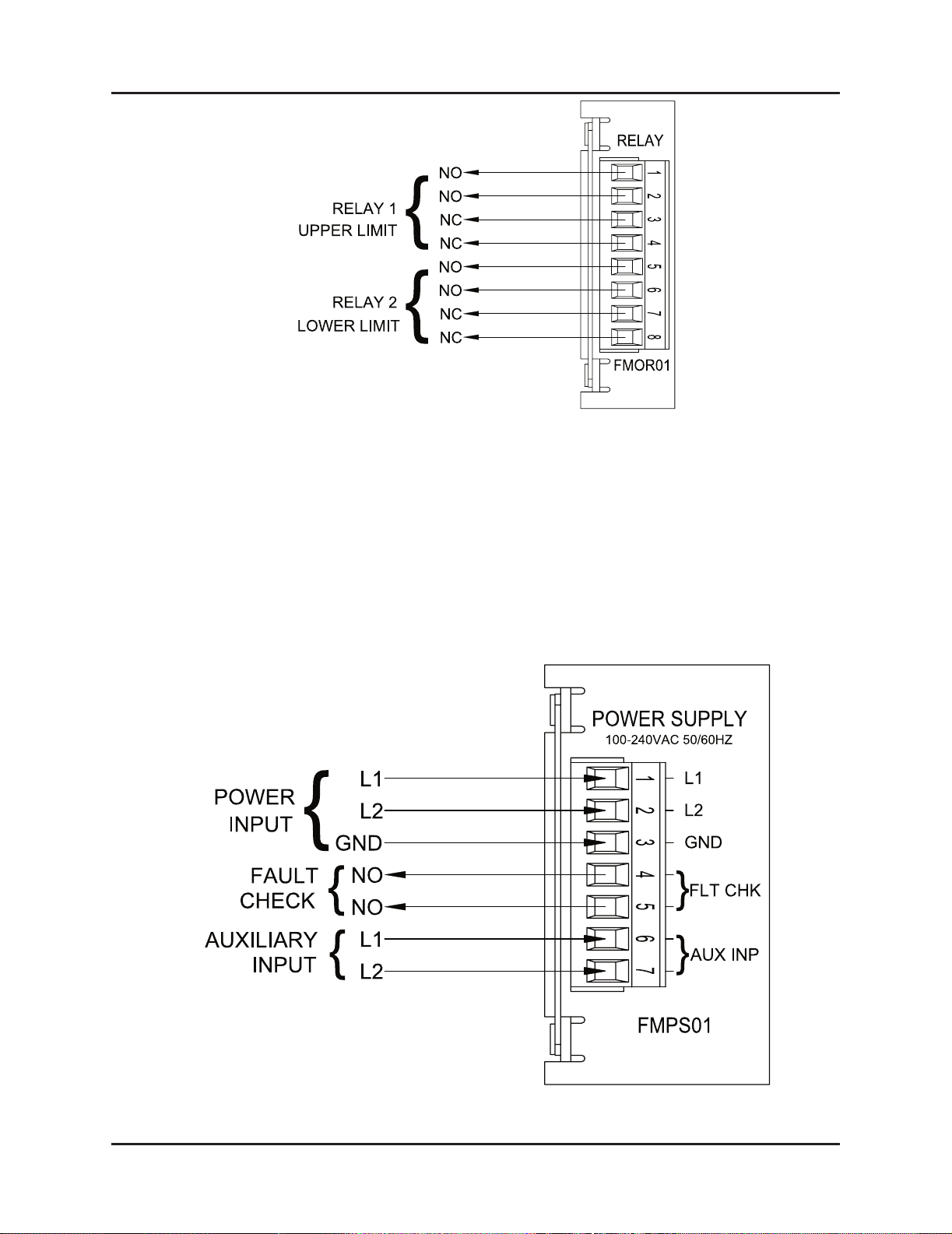
Relay Output Module (FMOR01)
The relay output module contains an upper and lower limit relay. Each relay contains a N.O.
contact pair and a separate N.C. contact pair. (See Figure 3-4). Each relay contact rating is 8
amps, 250 VAC, 30 VDC, 1/4 HP 125, 250 VAC. It is recommended that you connect these
relays to the ram adjust motor control circuit to prevent movement beyond the programmed
upper and lower limits. The terminal wire size is No. 22-12 AWG.
3.2: Wiring
Page 17
13
Installation and Programming Manual
Chapter 3: Mounting and Wiring
Figure 3-4 Relay Output Pinout Diagram
Figure 3-5 Power Supply Pinout Diagram
Power Supply Module (FMPS01)
The power supply module has a main power input, an auxiliary input, and a fault check output.
(See Figure 3-5). Power input: 85-265 VAC at 450 mA maximum. Fault check output: 8 amps
250 VAC, 30 VDC, 1/4 HP 125, 250 VAC. It is recommended that the fault check contacts be
connected to the required safety interlock for the press. Auxiliary input: 85-265 VAC at 12 mA
maximum. The terminal wire size for all connectors is No. 22-12 AWG. See page 3, 35, 36 and
37 for use of this special purpose input, concerning position hold and move detection.
Page 18
Installation and Programming Manual
14
Chapter 3: Mounting and Wiring
15
Installation and Programming Manual
Chapter 3: Mounting and Wiring
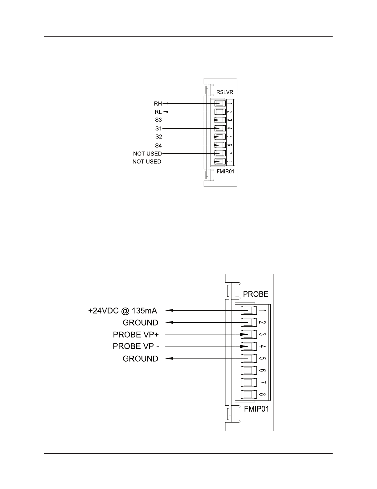
Resolver Module (FMIR01)
The resolver module has an eight-position connector. (See Figure 3-6). The terminal wire size
for all positions is No. 22-12 AWG. Terminal 7 and 8 are not used.
Figure 3-6 Resolver Pinout Diagram
Variable Pulse LDT Module (FMIP01) Input Option V1
The variable pulse LDT module has an eight-position connector. It is only necessary to connect
your LDT to positions 1 through 4. (See Figure 3-7). Positions 1 and 2 provide +24 VDC to
power the LDT. Positions 3 and 4 are used for the LDT’s pulse-width output signals. These
signals comprise an RS-422 differential input. Positions 5-8 are provided for future expansion.
The terminal wire size for all positions is No. 22-12 AWG. This module should only be used
with Gemco LDT model 951VP-2110 tranducers.
Figure 3-7 Variable Pulse LDT Pinout Diagram Input Option V1
Page 19

15
Installation and Programming Manual
Chapter 3: Mounting and Wiring
Figure 3-7 LDT Pinout Diagram Input Option L1
LDT Input (FMIP02) Input Option L1
This module will accept an output from a controlled pulse, start stop pulse or variable pulse
magnetostrictive LDT. (See Figure 3-7). This card accepts a wide range of LDT inputs and
provides faster updates than the variable pulse module as described on page 14.
The pulse width signal is converted to position data which the monitor displays. The module
also provides +24 VDC to supply power to the LDT. The monitor was designed to work
with the Gemco 951 or 952CP & RS LDTs. However, other LDTs can be used with the PLC
Interface Module. If you are using a different type of LDT, contact the factory for wiring and
programming instructions. The terminal wire size for all positions is No. 22-12 AWG.
The reset-to-preset input is an edge sensitive input that resets position data to a preprogrammed
value. A 5-24VDC source applied to these terminals activates the input. For programming of
reset value, see Chapter 4: Programming.
Digital Output (FMOD01) Output Option D1, D2 or D3
This module will output Binary, BCD, or Grey Code digital outputs in either current sinking,
current sourcing, or TTL level outputs. See Fig. 3-13A & B and Fig. 3-14 for wiring details. It
also contains a 5-24VDC source input for freezing the digital data while the PLC reads it. See
page 42, Latch/Synchronize Handshake.
Page 20

Installation and Programming Manual
16
Chapter 3: Mounting and Wiring
17
Installation and Programming Manual
Chapter 3: Mounting and Wiring
Figure 3-9 Digital Output Wiring Diagram
Drawing E0232200
Page 21

17
Installation and Programming Manual
Chapter 3: Mounting and Wiring
Figure 3-10 Digital Output Wiring Diagram
Drawing E0232200
Page 22

Installation and Programming Manual
18
Chapter 3: Mounting and Wiring
19
Installation and Programming Manual
Chapter 3: Mounting and Wiring
Analog Output (FMOA01) Output Option A1
The Analog Output board provides two channels of analog output that can be independently
congured and scaled. Each channel can be congured for an output based upon position or
velocity. Velocity will be RPM if the sensor is a resolver or inches/mm per second if the input
sensor is an LDT. The two channels of analog output allow you to congure one analog output
to be based on position while the other channel provides a simultaneous indication of velocity.
Terminal Wire Size: No. 22-12 AWG
Figure 3-11 Pinout Diagram Analog Output
Drawing E8005099
Page 23

19
Installation and Programming Manual
Chapter 3: Mounting and Wiring
Fig 3-12 Wiring Diagram Analog Output
Drawing E8005090
Page 24

Installation and Programming Manual
20
Chapter 3: Mounting and Wiring
21
Installation and Programming Manual
Chapter 3: Mounting and Wiring
Page 25

21
Installation and Programming Manual
Chapter 3: Mounting and Wiring
Fig 3-14 LDT - Based System Wiring Diagram
Drawing E0228700
Page 26

Installation and Programming Manual
22
Chapter 3: Mounting and Wiring
Fig 3-15 Wiring Monitor to Cable Termination Kit Drawing
Page 27

23
Installation and Programming Manual
Chapter 4: Programming
Chapter 4: Programming
This chapter provides detailed descriptions and instructions for programming all shut height
monitor’s functions. A complete list of functions (with brief explanations) can be found in
Appendix B: Function Summary Chart. This chapter divides the functions up into the following
seven sections.
4.1 Resolver Conguration Functions
4.2 LDT Conguration Functions
4.3 Monitor Setup Functions
4.4 Press Setup Functions
4.5 Digital Outputs
4.6 Program and Supervisory Mode Functions
4.7 Analog Outputs
Resolver conguration functions are used to congure the resolver to the shut height
monitor. (Refer to these functions only if you are using a resolver as an input device). LDT
conguration functions are used to congure a Linear Displacement Transducer (LDT) to
the shut height monitor. (Refer to these functions only if you are using an LDT as an input
device.) Conguration functions should be programmed before any other functions. Monitor
setup functions provide the means to customize the monitor’s setup for a specic installation.
Press setup functions provide the means to customize the press’s setup for a specic installation.
Program and supervisory mode functions are used to put the monitor in either program or
supervisory mode, as well as program the length of programming time and change the program
mode access code.
NOTE: Resolver or LDT conguration functions should be programmed rst before any
other type of programming is done. Refer only to your specic conguration section,
depending on which input device you are using.
Before You Start
Before conguring or programming the shut height monitor, the following must be done in the
following order:
n Jumper the monitor’s program lockout connector (J2). To jumper this con-
nector, see Section 3.2 Wiring.
n Put monitor in program mode. For instructions on putting the monitor in pro-
gram mode, see Program Mode Access in Section 4.6: Program and Supervisory Mode Functions.
The program mode LED will turn on when the monitor is in program mode.
Page 28

Installation and Programming Manual
24
Chapter 4: Programming
25
Installation and Programming Manual
Chapter 4: Programming
Figure 4-1 calls out the shut height monitor’s programming keys. Following this gure are
descriptions of these keys and how they work, as well as, a short tutorial on how to use the keys.
Figure 4-1 Programming Keys
Programming Keys Dened
The shut height monitor has four keys located on the front panel. These keys are used to
program functions and perform basic operations.
The function key is used to begin a process for programming a function.
When this key is pressed, the monitor prepares itself for the entry of a
specic function number.
The scroll key is used to scroll through the monitor’s list of function
numbers, as well as other lists. To scroll to a particular function number,
continue to select the scroll key (after selecting the function key) until the
monitor displays the desired function number. The scroll key is also used
to increment selected digits on the monitor’s LED display. Incrementing
digits can be done to either select a function number or a value for a
function. To move to a specic digit on the display, use the shift key. A
ashing digit indicates it is activated to be incremented. This key can also
be used to get you quickly back to an incorrect parameter - rather than
having to restart the function entry process. For example, if an invalid
parameter was entered in the Upper End Limit function, you could select
the scroll key. This would take the monitor back to displaying the current
value, where you could re-enter a new value.
↑
Status LEDs
Shift Key
Scroll Key
Function Key
Enter Key
AUX
MM
INCH
PROGRAM¹
FLT¹¹¹OK¹
MVT¹FLT¹
BOLSTER
UPR¹LIM ¹
LWR¹LIM ¹
BED
F
( )
(F)
2110
SERIES
Page 29

25
Installation and Programming Manual
Chapter 4: Programming
The shift key is used to move to a specic digit shown on the monitor’s
LED display. This can be done to either select a function number or a
value for a function. To move to a specic digit on the display, select the
function key and then the shift key. The right-most digit will then ash.
This indicates that the digit is activated to be incremented. (To increment
the digit, select the scroll key.) Continue to select the shift key until the
desired digit is activated.
The enter key is used for several purposes. For example, it is selected after
a function number is displayed. This begins the programming process for
the selected function. The enter key is also used to program a value in a
function. This is done by selecting the enter key after the desired value is
displayed on the monitor’s screen.
To customize the shut height monitor to your specic resolver and press installation, you must
rst make some congurations. These congurations are made through the use of resolver
conguration functions, which are described in this section. Following the descriptions of these
functions are instructions to congure your resolver. Perform these conguration procedures
before entering other function values or attempting to use the monitor to indicate shut height.
n Scale Factor (300)
n Turns Counting (301)
n Position Offset (302)
NOTE: The unit of measurement is set in inches at the factory. If you want the unit of
measurement to be set in millimeters, make this adjustment though the Unit of
Measurement function before programming the Position Offset function. Instructions
for programming the Unit of Measurement can be found in Section 4.3: Monitor Setup
Functions.
Scale Factor (300)
The Scale Factor function is used to program the number of counts or the resolution that one
revolution of the resolver results in. For example, when the function is programmed with a
value of 100, the shut height monitor will count from 0 to 99 as the resolver completes a full
revolution. The default value for this function is 4096. There is no maximum value that can be
programmed for this function.
4.1: Resolver Conguration Functions
8
←
Page 30

Installation and Programming Manual
26
Chapter 4: Programming
27
Installation and Programming Manual
Chapter 4: Programming
Turns Counting (301)
The Turns Counting function denes the number of revolutions the resolver must rotate before
the scale factor is reached. For example, when this function is set at 2 and the scale factor is
set at 100, the resolver will have to make two full revolutions before 100 counts is reached.
The Turns Counting Function can be disabled by setting its value to 0. When disabled, the
scale factor will cover its entire range in one revolution and roll over to 0 after one complete
revolution. When the Turns Counting function is set to 1, the total count will increase by the
scale factor for each revolution. For example, if the scale factor were set at 100 and turns
counting at 1, after ve revolutions, the monitor would display 500 counts. The default value for
this function is 0.
Position Offset (302)
The Position Offset function is used to syncronize the resolver’s position with the actual
machine position. The default value for this function is 0. This function is used to adjust the shut
height monitor’s indicated position so that it truly reects the press’s shut height. There is no
maximum value that can be programmed for this function.
Congure the Resolver
This subsection provides the necessary instructions to congure the shut height monitor to your
resolver. Perform these steps before attempting to use the monitor to indicate shut height. Once
these steps have been performed they will not have to be repeated.
1. Select the function key.
The monitor displays “F-----”.
2. Enter function number 10. (This is the Program Mode Access function which
allows you to put the monitor in program mode. Only when the monitor is in
program mode can other functions be programmed.) Select the enter key.
The monitor displays “000000”.
NOTE: If the shut height monitor displays only one zero (i.e. “0”), then the program lockout
connector is not jumpered. For wiring instructions, see Section 3.2: Wiring.
3. Enter either the program mode access code. The default code is 2100. Select
the enter key.
The monitor is now in program mode. The program mode LED is turned on.
10
Enter program mode
access code
(F)
8
8
Page 31

27
Installation and Programming Manual
Chapter 4: Programming
NOTE: The shut height monitor is defaulted to stay in program mode for 120 seconds. The
monitor will drop out of program mode if a key is not pressed within this time. If this
occurs, you will have to repeat steps 1-3. Further, the access code (2100) is provided
initially. This code can be changed through the use of the New Access Code function.
For security reasons, this function can only be implemented when the monitor is in
supervisory mode. For more information on New Access Code, contact the factory.
Enter Scale Factor for the Conguration Process
NOTE: If you know the desired scale factor value, go to Step 17 on page 31.
4. Select the function key.
The monitor displays “F-----”.
5. Select function number 300. (This is the Scale Factor function.) Select the
enter key.
The monitor displays the function’s current value.
6. Enter 001000. (This value will change the scale factor to produce 1000
counts per resolver revolution.) Select the enter key.
Set Turns Counting to 1
7. Select the function key.
The monitor displays “F-----”.
8. Select function number 301. (This is the Turns Counting function.) Select the
enter key.
The monitor displays the function’s current value.
9. Enter 000001. (This value will cause the position to continue to increment after
each revolution.) Select the enter key.
10. Using a dial indicator with a minimum of 1.000” of travel and a magnetic base,
afx the indicator between the bolster plate and ram. Zero the dial indicator.
Enter
001000
300
301
Enter
000001
Follow
step 10
(F)
8
8
(F)
8
8
Page 32

Installation and Programming Manual
28
Chapter 4: Programming
29
Installation and Programming Manual
Chapter 4: Programming
NOTE: The shut height monitor is defaulted to display position in inches. It can be changed to
read position in millimeters, however. To make this change, see Unit of Measurement in
Section 4.3: Monitor Setup Functions. Steps 11-13 will have to be repeated if the unit of
measurement is changed.
Set the Position Offset to 0
11. Select the function key.
The monitor displays “F-----”.
12. Select function number 302. (This is the Position Offset function.) Select the
enter key.
The monitor displays the function’s value.
13. Enter 000000. (This value will set the indicated shut height position offset to
0 in comparison with the current position of the ram.) Select the enter key.
14. Move the slide adjust until the ram has moved 1.000” according to the dial
indicator.
15. Divide 1.000 by the number the monitor is displaying. Include all digits
(including the decimal point) in the calculation.
16. Multiply the result of step 15 by 1000.
Enter Newly Determined Scale Factor
17. Select the function key.
The monitor displays “F-----”.
18. Select function number 300 (Scale Factor function). Select the enter key.
The monitor displays “001000”.
19. Enter the result of step 16, including digits up to a maximum of three spaces
to the right of the decimal point. Select the enter key.
300
Enter sum
of step 16
302
Follow steps
14-16
Enter
000000
(F)
8
8
(F)
8
8
Page 33

29
Installation and Programming Manual
Chapter 4: Programming
Adjust the Turns Counting Factor
20. Select the function key.
The monitor displays “F-----”.
21. Select function number 301 (Turns Counting function). Select the enter key.
The monitor displays “001000”.
22. Enter 001000. Select the enter key.
23. Select the function key.
The monitor displays “F-----”.
24. Select function number 302 (Position Offset function). Select the enter key.
The monitor displays the current position of the shut height.
25. Enter the actual position of the shut height as measured from the bed to the
ram. It is recommended that a set of inside micrometers be used to acquire
this information.
To verify that you have accurately calibrated the resolver, move the slide
adjust 1.000”. After this has been done, the new position indicated should
also have moved 1.000”.
After conguring the resolver to the shut height monitor, you can proceed to
Section 4.3: Monitor Setup functions.
301
Enter
001000
Enter
000000
302
There are two input cards available for use with LDTs.
1. Specied as option V1 in the part number and is labeled (FMIP01) on the card.
2. Specied as option L1 in the part number and is labeled (FMIP02) on the card.
The conguration of the module and this LDT is different depending on which module you have
ordered. Determine which module you have and proceed to the section below for programming
instructions.
4.2: LDT Conguration Functions
(F)
8
8
(F)
8
8
Page 34

Installation and Programming Manual
30
Chapter 4: Programming
31
Installation and Programming Manual
Chapter 4: Programming
Wire Speed (300)
Programming of the wire speed synchronizes the performance of the module with the performance
of the LDT. You will nd the wire speed on the legend plate of your LDT.
To program wire speed, perform the following steps:
1. Select the function key.
The monitor displays “F-----”.
2. Select function number 300 . Select the enter key.
The monitor displays the function’s current value.
3. Enter the new wire speed value. Select the enter key. Count Direction (301)
300
Enter new
value
4.2
Option V1 - This module can only be used with Gemco LDTs with a part number starting with
951VP1992 or 951VP2110.
Wire speed and recirculations for these LDTs have been congured at the factory for maximum
resolution.
NOTE: Always refer to the LDT legend plate for programming wire speed (Function 300). The
wire speed will always be between 500.000 and 600.000 micro sec./inch.
Option L1 - This module is designed to be used with any LDT with digital output. These
include Series 951, 952 with VP, RS or CP outputs.
This module provides faster updates of position while using the LDT with standard wire speeds.
NOTE: Review the LDT legend plate for correct wire speed. Wire speed will always be
between 8.000 and 10.000 micro sec./inch.
NOTE: If option L1 is used, the rst step in conguration must be Function 307 (LDT Type)
that tells the module which LDT is being used.
NOTE: Before an LDT conguration function can be programmed, the shut height monitor
must be in program mode. To put the monitor in program mode, see Program Mode
Access in Section 4.6: Program and Supervisory Mode Functions.
(F)
8
8
Page 35

31
Installation and Programming Manual
Chapter 4: Programming
Count Direction (301)
The Count Direction function is used to change the direction the shut height position will move
as the LDT’s magnet travels along the guide rail. A 0 value will cause the position to increment
as the magnet moves away from the LDT head. A value of 1 will cause the position to increment
as the magnet moves toward the LDT head. The default for this function is 1. For further
explanations, see Figure 4-2. To change the value of the Count Direction function, perform the
following steps:
1. Select the function key.
The monitor displays “F-----”.
2. Select function number 301 . Select the enter key.
The monitor displays the function’s current value.
3. Enter either a 0 or 1. Select the enter key.
301
Enter either
0 or 1
Figure 4-2 Count Direction Function
Count Direction Function = 0 Count Direction Function = 1
100
100
When the Count Direction Function is
programmed with a value of 0, the
monitor will increment when the LDT’s
magnet assembly is moving away from
the head of the LDT.
When the Count Direction Function is
programmed with a value of 1, the
monitor will increment when the LDT’s
magnet assembly is moving toward the
head of the LDT.
0
0
(F)
8
8
Page 36

Installation and Programming Manual
32
Chapter 4: Programming
33
Installation and Programming Manual
Chapter 4: Programming
1. Select the function key.
The monitor displays “F-----”.
2. Select function number 302 . Select the enter key.
The monitor displays the current shut height position.
3. Enter the new position offset value. Select the enter key.
Position Offset (302)
NOTE: Make sure the unit of measurement function is selected to your desired units before
entering the value for the Position Offset function. The unit of measurement is set in
inches at the factory. For instructions on selecting the unit of measurement, see Unit of
Measurement in Section 4.3: Monitor Setup Functions.
The Position Offset function is used to synchronize the monitors displayed value with actual
shut height. This value can range from -99.999 to 999.999 inches. With the LDT installed on
the press and functioning properly, physically measure the shut height. Enter the measured
value in this function. To change the value of the Position Offset function, perform the
following steps:
Enter current
Shut Height
Position
Zero Pulse Time (305)
The Zero Pulse Time function is used to enter the pulse time that the monitor will recognize as
the absolute zero position on the LDT. The default for this function is 1.000 millisecond. This
value matches the Zero Pulse Time of the 951VP-1992 and should not require an adjustment.
The zero pulse time value can range from 1.000 to 99.999 milliseconds. To change the value of
the Zero Pulse Time function, perform the following steps:
1. Select the function key.
The monitor displays “F-----”.
2. Select function number 305 . Select the enter key.
The monitor displays the function’s current value.
3. Enter the new zero pulse time. Select the enter key.
305
Enter new
zero pulse
time
302
(F)
8
8
(F)
8
8
Page 37

33
Installation and Programming Manual
Chapter 4: Programming
Fault Pulse Time (306)
The Fault Pulse Time function is used to program the pulse time of the fault signal sent by the
LDT when it detects an error. When the monitor receives a fault signal of this pulse time, it
will indicate an error (see Appendix A: Error Messages). The default for this function is 10
microseconds. This value can range from 1 to 99 microseconds. A 0 is entered in this function
to disable it. To change the value of the fault pulse time or disable this function, perform the
following steps:
NOTE: Do not change the value unless using an LDT other than Gemco.
1. Select the function key.
The monitor displays “F-----”.
2. Select function number 306 . Select the enter key.
The monitor displays the function’s current value.
3. Enter a 0 to disable this function or enter a new fault pulse time. Select the
enter key.
After conguring the LDT to the shut height monitor, you can proceed to
Section 4.3: Monitor Setup Functions.
307
LDT Output Type (307)
This function is used to congure the L1 input board for use with a specic LDT output.
Review legend plate of the LDT for output type, i.e. CP, RS or VP. Perform the following
steps:
1. Select the function key.
The monitor displays “F-----”.
2. Select function number 307 . Select the enter key.
Enter either:
0 = CP
1 = RS
2 = VP (external interrogation) (See Note below)
3 = VP (internal interrogation)*
NOTE: The Variable Pulse with external interrogation mode is not compatable with the 952 probe.
When using a 952 probe, select a different mode of operation.
Enter New
Value
306
(F)
8
(F)
8
8
Page 38

Installation and Programming Manual
34
Chapter 4: Programming
35
Installation and Programming Manual
Chapter 4: Programming
3. Enter a 0 to disable this function or enter a new output type. Select the enter
key.
*If used, program Function 308. Consult the factory for settings.
This section provides descriptions and instructions for the shut height monitor setup functions.
These functions provide the means to customize the monitor’s setup for a specic installation.
Before any of these functions can be programmed, the monitor must be in program mode. To
put the monitor in program mode, see Program Mode Access in Section 4.6: Program and
Supervisory Mode Functions. The following is a list of the monitor setup functions:
n Unit of Measurement (14)
n Decimal Location (13)
n Position Hold (15)
n Auxiliary LED (16)
Unit of Measurement (14)
The Unit of Measurement function is used to select the unit of measurement for the shut height
and all position data. Measurements can be either in inches or millimeters. Enter a 0 to select
inches or enter a 1 to select millimeters. The default for this function is 0. To change the unit of
measurement, perform the following steps:
1. Select the function key.
The monitor displays “F-----”
2. Enter function number 14. Select the enter key.
The monitor displays the function’s current value.
3. Enter either 0 or 1. Select the enter key.
NOTE: If you change the unit of measurement, the decimal location shown on the monitor’s
LED display will change to the default position for the unit of measurement selected.
If you select millimeters, position data will be displayed in hundredths; selecting
inches will display data in thousandths. For more information, see Decimal Location.
Enter either 0
or 1
14
NOTE: The Unit of Measurement should be programmed prior to the scale factor on systems
using a resolver input.
4.3: Monitor Setup Functions
(F)
8
8
8
Page 39

35
Installation and Programming Manual
Chapter 4: Programming
Decimal Location (13)
The Decimal Location function is used to program the resolution of the shut height and all
position data shown on the monitor’s LED display. Resolution can be either displayed in whole
units, tenths, hundredths, or thousandths. Resolution choices correspond to the following values:
0 = whole unit; 1 = tenths; 2 = hundredths; and 3 = thousandths. To change the resolution
shown on the monitor’s LED display, perform the following steps:
1. Select the function key.
The monitor displays “F-----”
2. Select function number 13. Select the enter key.
The monitor displays the function’s current value.
3. Enter either a 0, 1, 2, or 3. Select the enter key.
Position Hold (15)
The Position Hold function stops the monitor from displaying irrelevant uctuations during a
press’s stamping cycle. When the monitor’s auxiliary input is activated, this function will hold
the last position read. Either a 0, 1, or 2 can be programmed in this function. Entering a 1 will
cause the monitor to hold the last position read when power is applied to the auxiliary input.
Entering a 2 will cause the monitor to hold the last position read when power is taken away
from the auxiliary input. Entering a 0 disables this function. The default for this function is 0.
Enabling this function disables the Move Detection Time-Out function. When the Position Hold
function is enabled, the value for the Move Detection Time-Out is then used for the Position
Hold dwell time. The position hold dwell time is the amount of time the monitor continues to
hold the shut height position after the auxiliary input is released (or activated, depending on
the input’s programmed state). To enable or disable the Position Hold function, perform the
following steps:
1. Select the function key.
The monitor displays “F-----”
2. Enter function number 15. Select the enter key.
The monitor displays the function’s current value.
3. Enter either 0, 1, or 2. Select the enter key.
NOTE: The default time for the position hold dwell may be too long for your application. To
change this value for your application, perform the following steps.
15
Enter either
0, 1, 2, or 3
13
Enter either
0, 1, or 2
(F)
8
8
(F)
8
8
Page 40

Installation and Programming Manual
36
Chapter 4: Programming
37
Installation and Programming Manual
Chapter 4: Programming
4. The default value for the Move Detection Time-Out function is 5.00 seconds.
To change this value for the position hold dwell time, select the function key.
The monitor displays “F-----”
5. Enter function number 12. Select the enter key.
The monitor displays the current value for the position hold dwell time. This
value is in seconds.
6. Select the new dwell time. Select the enter key.
NOTE: The Position Hold function only holds the position on the monitor’s LED display.
Internally, the shut height position and the upper and lower limit relays are continually
being updated. In addition, the auxiliary LED can be used to determine when a position
hold occurs. However, this LED must be selected for this feature. To enable this LED,
see Auxiliary LED.
Auxiliary LED (16)
The Auxiliary LED function is used to enable the monitor’s auxiliary LED. This LED is
currently used only to indicate a position hold. (For more information, see Position Hold). Either
a 0 or 1 can be programmed in this function. Entering a 0 will disable the LED. Entering a 1 will
enable the LED to turn on when a position hold occurs. The default for this function is 0. To
enable or disable the auxiliary LED, perform the following steps:
1. Select the function key.
The monitor displays “F-----”
2. Select function number 16. Select the enter key.
The monitor displays the function’s current value.
3. Enter either 0 or 1. Select the enter key.
Enter new
dwell value
12
Enter either 0
or 1
16
(F)
8
8
(F)
8
8
Page 41

37
Installation and Programming Manual
Chapter 4: Programming
This section provides descriptions and instructions for press setup functions. These functions
provide the means to customize the press’s setup for a specic installation. Before these
functions can be programmed, the monitor must be in program mode. To put the monitor in
program mode, see Program Mode Access in Section 4.6: Program and Supervisory Mode
Functions. The following is a list of the press setup functions:
n Move Detection Time-Out (12)
n Bolster Offset (303)
n Negative Over Travel Limit (304)
n Upper End Limit (400)
n Lower End Limit (401)
n Relay State (402)
n Relay Override (403)
Move Detection Time-out (12)
The Move Detection Time-out function is used to program the time the press’s shut height
must move within when power is applied to the ram adjust motor(s). The default value for this
function is 5.00 seconds. This value can range from 0 to 99.99 seconds. Entering a 0 disables
this function. The purpose of this function is to detect a possible jam or drive component failure.
When power is applied to the press’s ram adjust motor(s), the monitor’s auxiliary input receives
an AC voltage. When this occurs, the monitor begins to look for shut height movement. If
movement is not detected within the programmed time, the upper and lower limit relays will
de-energize and the fault check relay will open. Also, the movement fault LED will turn on and
the monitor will display an error message (see Appendix A: Error Messages). This error will
have to be cleared before machine operation can resume. To change the move detection time-out
value or disable the function, perform the following steps:
1. Select the function key.
The monitor displays “F-----”
2. Enter function number 12. Select the enter key.
The monitor displays the function’s current value.
3. Enter the new time-out value. Select the enter key.
12
Enter new
time-out
value
4.4: Press Setup Functions
(F)
8
8
Page 42

Installation and Programming Manual
38
Chapter 4: Programming
39
Installation and Programming Manual
Chapter 4: Programming
NOTE: The power supply’s auxiliary input must be wired properly in order for the Move
Detection Time-Out function to work. For instructions on wiring the auxiliary input,
see Section 3.2: Wiring.
Bolster Offset (303)
The Bolster Offset function is used to program the thickness of a bolster plate installed on
the bed of the press. The value programmed in this function is internally subtracted from the
programmed shut height. This function’s value cannot exceed the maximum scaled position.
The default for this function is 0.000 inches. This value can range from 0.000 to 999.999 inches.
When this function contains a value of 0, the monitor’s bolster LED will turn off, indicating no
bolster plate is installed. Only when this function contains a value other than 0 will this LED
turn on. To program a value in the bolster offset function, perform the following steps:
1. Select the function key.
The monitor displays “F-----”
2. Select function number 303. Select the enter key.
The monitor displays the function’s current value.
3. Enter the new bolster offset value. (This is the thickness of the bolster plate.)
Select the enter key.
Negative Over Travel Limit (304)
The Negative Over Travel Limit function is used to program the maximum allowable distance
the shut height can travel below zero before the monitor will give an error. If the shut
height moves beyond this position, the upper and lower limit relays will de-energize and the
fault check relay will open. The monitor will also display an error (see Appendix A: Error
Messages). This error must be cleared before machine operation can resume. The default for
this function is 0.050 inches. This value can range from 0 to 999.999 inches. The value entered
in this function is a positive number, however, the limit is negative because it is below zero.
Typical shut height readings may never approach zero. However, for installations that do,
this function limits the height adjustment when it goes below zero. To change the value of the
Negative Over Travel Limit function, perform the following steps:
1. Select the function key.
The monitor displays “F-----”
2. Select function number 304. Select the enter key.
The monitor displays the function’s current value.
Enter bolster
offset
303
304
(F)
8
(F)
8
8
Page 43

39
Installation and Programming Manual
Chapter 4: Programming
3. Enter the new value. Select the enter key.
If your system includes the optional relay module (K1), the following function numbers are used
for setup. Before these functions can be programmed, the monitor must be in program mode.
To put the monitor in program mode, see Program Mode Access in Section 4.7: Program and
Supervisory Mode Functions. The following is a list of the press setup functions.
• Upper End Limit (400)
• Lower End Limit (401)
• Relay State (402)
• Relay Override (403)
Upper End Limit (400)
The Upper End Limit function is used to program the upper limit of the shut height opening.
This can prevent the ram from accidentally exceeding its mechanical adjustment capabilities.
If the shut height reaches or exceeds the value programmed in this function, the upper limit
relay will de-energize and the upper limit LED will turn on. This can cause power to be taken
away from the press’s ram adjust motor(s) if the upper limit relay is properly wired. (For wiring
instructions, see Section 3.2: Wiring.) The default for this function is 999.999 inches. This
value can range from 0 to 999.999 inches. To program a value for the Upper End Limit function,
perform the following steps:
1. Select the function key.
The monitor displays “F-----”
2. Enter function number 400. Select the enter key.
The monitor displays the function’s current value.
3. Enter the new value. Select the enter key.
NOTE: To temporarily regain lost power to the ram adjust motor(s) (close the upper end limit
relay) if the shut height reaches or exceeds the upper end limit, see Relay Override.
Enter new
setting
400
Enter upper
limit
4.4: Relay Setup Functions - Option K1
(F)
8
8
8
Page 44

Installation and Programming Manual
40
Chapter 4: Programming
41
Installation and Programming Manual
Chapter 4: Programming
Lower End Limit (401)
The Lower End Limit function is used to program the lower end limit of the shut height
opening. This can prevent the ram from accidentally exceeding its mechanical adjustment
capabilities. If the shut height reaches or goes below the value programmed in this function,
the lower limit relay will de-energize and the lower limit LED will turn on. This can cause
power to be taken away from the press’s ram adjust motor(s) if the lower limit relay is properly
wired. (For wiring instructions, see Section 3.2: Wiring.) The default for this function is 0.000
inches. This value can range from 0 to 999.999 inches. To program a value for the Lower End
Limit function, perform the following steps:
1. Select the function key.
The monitor displays “F-----”
2. Enter function number 401. Select the enter key.
The monitor displays the function’s current value.
3. Enter the new value. Select the enter key.
NOTE: To temporarily regain lost power to the ram adjust motor(s) (close the lower end limit
relay) if the shut height reaches or goes below the lower end limit, see Relay Override.
Relay State (402)
The Relay State function is used to program the monitor’s upper and lower limit relays to either
energize or de-energize when the monitor is in normal machine operation. Either a 0 or 1 can
be programmed in this function. Entering a 0 will cause the monitor to energize the relays
during machine operation, and de-energize the relays when a limit is exceeded or when an error
occurs. Entering a 1 will cause the monitor to de-energize the relays during machine operation,
and energize the relays when a limit is exceeded or when an error occurs. The default for this
function is 0. To change the state of these relays, perform the following steps:
1. Select the function key.
The monitor displays “F-----”
2. Enter function number 402. Select the enter key.
The monitor displays the function’s current value.
3. Enter either a 0 or 1. Select the enter key.
401
Enter lower
end limit
Enter either
0 or 1
402
(F)
8
(F)
8
8
8
Page 45

41
Installation and Programming Manual
Chapter 4: Programming
2. Enter function number 403. Select the enter key.
The monitor displays “000000”
3. Enter the override code 2110. Select the enter key.
NOTE: After re-energizing either the upper or lower limit relays, the operator should move the
shut height back into its range between its upper and lower limits. If the shut height is
again moved in the wrong direction (towards the limits), the upper or lower limit relays
will again de-energize, if the relays were programmed to do so. Step 1 - 3 will have to
then be repeated.
Enter 2110
403
If your system has been purchased with the optional digital output module, the following
programming sequence will be used to congure the board for compatibility with the PLC input
card.
Output Type (200)
This function will set up the D25 connector on the digital board to output the current position
value in a Binary, BCD or Grey code format:
1. Select the function key.
The monitor displays “F-----”
2. Enter function 200. Select the enter key.
The monitor displays the function’s current value.
3. Enter either 0, 1 or 2.
0 = Binary (default)
1 = BCD
2 = Grey
Select the enter key.
200
Relay Override (403)
The Relay Override function is used to temporarily allow the press operator to readjust the
shut height once it has exceeded a programmed end limit. If the upper or lower limit relays are
wired into the power interlock system, power may be lost when the shut height goes beyond the
values programmed in the upper or lower limit functions. (For more information, see Upper End
Limit and Lower End Limit.) To override either the upper or lower limit relays, perform the
following steps:
1. Select the function key.
The monitor displays “F-----”
Enter either
0, 1 or 2
4.5: Digital Outputs
(F)
8
8
(F)
8
8
Page 46

Installation and Programming Manual
42
Chapter 4: Programming
43
Installation and Programming Manual
Chapter 4: Programming
Logic Level (202)
This function will set up selection of either high true or low true.
1. Select the function key.
The monitor displays “F-----”
2. Enter function 202. Select the enter key.
The monitor displays the function’s current value.
3. Enter either 0 or 1.
0 = Low True
1 = High True (default)
Select the enter key.
Latch/Synchronize Handshake (201)
The function denes which of the two methods will be used to stabilize position data while
the PLC reads. The two options are Latch or Synchronize Handshake. Synchronize Handshake
tells the digital board to update on the transitional edge of a clocked square wave input (pin
24). Latch tells the digital board to update continuously until the latch input pin is activated by
driving high, then the outputs will freeze.
NOTE: If set for Synchronize handshake, the position data will never update if a square wave
input is not seen on pin 24.
1. Select the function key.
The monitor displays “F-----”
2. Enter function 201. Select the enter key.
The monitor displays the function’s current value.
3. Enter either 0 or 1.
0 = Latch (default)
1 = Synchronize
Select the enter key.
Enter either
0 or 1
201
Enter either
0 or 1
202
(F)
8
8
(F)
8
8
Page 47

43
Installation and Programming Manual
Chapter 4: Programming
Error Condition Output State (203)
This function allows you to select how the digital outputs will react to a failure in the encoder
module, transducer and/or cable. The following three options describe what will happen on a
failure.
1. Select the function key.
The monitor displays “F-----”
2. Enter function 203. Select the enter key.
The monitor displays the function’s current value.
3. Enter either 0, 1 or 2.
0 = All Outputs Off (default)
1 = All Outputs On
2 = Last Valid Position
Select the enter key.
0, 1 or 2
203
Enter either
8
(F)
8
Page 48

Installation and Programming Manual
44
Chapter 4: Programming
45
Installation and Programming Manual
Chapter 4: Programming
REPLACE “X” WITH SLOT LOCATION
Analog Output Channel 1
A) Select voltage or current output
1. Select the function key.
The monitor displays “F-----”
2. Enter function number X04. Select the enter key.
The monitor displays the current function value.
0 = voltage output
1 = current output
3. Leave current value or change. Select enter key.
X04
Enter
0 or 1
8
(F)
8
4.6: Analog Outputs
The Analog Output board provides two channels of analog output that can be independently
congured and scaled. Each channel can be congured for an output based upon position.
Each of the two analog output channels generate a simultaneous voltage and current output.
You can use either the current or voltage output on one channel but not both.
The following programming sequences require that you specify your intent to use either the
voltage or current output for each channel prior to programming the output scaling. You can
congure one analog channel for use of its voltage output and congure the other channel for
current.
The analog output board will be factory installed in slot 2 or slot 4 of the Series 2110 module’s
chassis. Look at the back of your Series 2110 module and verify which slot your analog output
board has been installed in. The following programming function numbers are shown with an
“X” as the rst digit. The “X” must be replaced with the number 2 or 4 which corresponds to
the slot in which your analog output board was installed at the factory.
NOTE: Boards cannot be changed from their factory supplied slot location in the eld.
It is recommended that you congure and program the analog output in the following sequence.
Perform all programming steps for one output channel before proceeding to the other output
channel.
Page 49

45
Installation and Programming Manual
Chapter 4: Programming
3. Enter function number X02. Select enter key.
The monitor displays current minimum position value.
4. Enter 500. Select enter key. This sets minimum position value at 500 counts.
The monitor displays 000500.
5. Select function key.
The monitor displays “F----”.
6. Enter function number X05. Select enter key.
The monitor displays current voltage output value linked to minimum
position value.
7. Enter 2. Select enter key. This sets a minimum voltage output value of
2VDC for 500 counts or less.
The monitor displays 002000.
C) Scaling Analog Output
The analog output is scaled by programming a minimum position value followed by the
analog output value required at that position. A maximum position value is then
programmed followed by the analog output required at that position.
The analog output value specied can be any value within the following allowable
range:
Voltage -10 VDC to 10 VDC
Current 0mA to 20mA
The analog output will stop changing upon reaching the minimum and maximum values
programmed. This allows selection of a nonstandard output like 2 to 8 VDC or 10 to 20
mA.
The position range over which the analog output develops can be any portion of the total
change seen by the Interface Module.
Example: Program analog output channel 1 for 2 to 8 VDC over 500 to 2000 count
change.
1. Select Voltage output as described earlier under step A
2. Select function key.
The monitor displays “F----”.
8
(F)
8
8
8
X02
Enter
000500
X05
Enter
002000
(F)
Page 50

Installation and Programming Manual
46
Chapter 4: Programming
47
Installation and Programming Manual
Chapter 4: Programming
8. Select function key.
9. Enter function number X03. Select enter key.
The monitor displays current maximum positions value.
10. Enter 2000. Select enter key. This sets maximum position value at 2000
counts.
The monitor displays 002000.
11. Select Function key.
The monitor displays “F-----”.
12. Enter function number X06. Select enter key.
The monitor displays current voltage output value linked to maximum count
value.
14. Enter 8. Select enter key. This sets a maximum voltage output value of
8VDC at 2000 counts or more.
The monitor displays 008000.
Analog output channel 2 is programmed using the same basic sequences except with the
function numbers noted below. Remember that the X shown in the function number represents
the slot in which the analog output board is installed in the Interface Module chassis.
Analog Output Channel 2 - Function numbers
A) Select voltage or current output
Function No. X10
B) Scaling analog output
- Select minimum position
Function No. X08
- Select analog output value to be linked to minimum position value
Function No. X11
Analog output channel 1 will now provide a 2 to 8 VDC output as position increases between
500 and 2000 counts. Position values below 500 will result in a 2 VDC analog output. Position
values above 2000 will result in an 8 VDC output.
8
8
8
8
X03
Enter
002000
X06
Enter
008000
(F)
(F)
Page 51

47
Installation and Programming Manual
Chapter 4: Programming
This section provides descriptions and instructions for program and supervisory mode functions.
These functions are used to put the shut height monitor in either program or supervisory mode,
as well as program the length of programming time and change the program mode access code.
Before a function can be programmed, the monitor must be in program mode. This is done
through the Program Mode Access function, which is the rst function described in this section.
The monitor can also be put in supervisory mode. Putting the monitor in this mode allows
supervisory functions. Instructions for putting the monitor in this mode are also described in
Program Mode Access. The following is a list of the program and supervisory mode functions:
n Program Mode Access (10)
n Program Mode Time-Out (11)
n New Access Code (90)
NOTE: The controller’s program lockout connector (J2) must be jumpered to allow the unit to
enter program mode. For wiring instructions, see Section 3.2: Wiring.
Program Mode Access (10)
The Program Mode Access function is used to put the shut height monitor in either program
or supervisory mode. Only when the monitor is in program mode can other functions be
programmed. The monitor is defaulted to stay in program mode for 120 seconds (see Program
Mode Time-Out). The monitor will drop out of program mode if a key is not pressed within this
time. A program mode access code must be entered in this function in order to put the monitor
in program mode. The monitor can also be put in supervisory mode. Only when the monitor is
in supervisory mode can supervisory functions be programmed. A supervisory mode access
code must be entered in order to put the monitor in supervisory mode. For security reasons,
this code was not sent with this manual. Contact AMETEK to receive this code. To place the
monitor in either program or supervisory mode, perform the following steps:
1. Select the function key.
The monitor displays “F-----”
2. Enter function number 10. Select the enter key.
The monitor displays “000000”
10
4.7: Program and Supervisory Mode Functions
8
(F)
- Select maximum position value
Function No. X09
- Select analog output value to be linked to maximum position value
Function No. X12
Page 52

Installation and Programming Manual
48
Chapter 4: Programming
NOTE: If the shut height monitor displays only one zero (i.e. “0”), then the program lockout
connector is not jumpered. For wiring instructions, see Section 3.2: Wiring.
3. Enter either the program or supervisory mode access code. The default
program mode access code is 2100. Select the enter key.
The monitor is now in either program mode or supervisory mode. The
program mode LED is turned on.
NOTE: The shut height monitor can be taken out of program or supervisory mode at any time
by entering an invalid access code in the Program Mode Access function. Further, the
access code (2100) is provided initially. However, this code can be changed through
the use of the New Access Code function. For security reasons, this function can only
be implemented when the monitor is in supervisory mode. For more information on
New Access Code, contact the factory.
Program Mode Time-Out (11)
The Program Mode Time-out function is used to change the duration of time the monitor will
stay in program mode once the Program Mode Access function is entered (see Program Mode
Access). If a key is not pressed within the time programmed in this function, the monitor will
drop out of program mode. Every time a key is pressed, the timer will restart. The default for
this function is 120 seconds. This value can range from 10 to 1000 seconds. To change the
program mode time-out value, perform the following steps:
1. Select the function key.
The monitor displays “F-----”
2. Select function number 11. Select the enter key.
The monitor displays the function’s current value.
3. Enter the new time-out value. Select the enter key.
NOTE: The Program Mode Time-Out function serves two purposes. The rst is that when
the monitor is in program mode and a key is not pressed within the time-out delay,
this function will take the monitor out of program mode. The second purpose is that
when the monitor is displaying something other than the shut height, and is or is not
in program mode, and a key is not pressed within the time-out delay, this function will
force the monitor to display the current shut height position.
Enter new timeout value
11
Enter access
code
8
(F)
8
8
Page 53

49
Installation and Programming Manual
Appendix A: Error Messages
Appendix A: Error Messages
The shut height monitor displays an error message when an error occurs during machine
operation. The format for errors appearing on the monitor’s LED display is illustrated in
Figure A-1. Descriptions and solutions for errors are provided in charts A-1 through A-3. Error
messages are grouped into the following three categories:
System Error This type of error is caused by one of the monitor’s modules or
input device. It typically indicates some form of a hardware failure
or problem with the input device. For example, if the input device
is disconnected from the input module, the monitor will display a
system error.
Operating Error This type of error is caused by problems with typical machine
operation. For example, if the press’s shut height does not move
within the time programmed in the Move Detection Time-Out
function, the monitor will display an operating error.
Entry Error This type of error is caused by an invalid entry through the use of
the monitor’s keypad. For example, if an invalid function number
is entered or a value for a function that is out of range is entered,
the monitor will display an entry error.
NOTE: To clear errors, perform the solutions found in charts A-1, A-2, and A-3. After
completing the solution, press the enter key.
Page 54

Installation and Programming Manual
50
Appendix A: Error Messages
51
Installation and Programming Manual
Appendix A: Error Messages
Figure A-1: Characteristics of an Error Message
Describes the Type of Error
SEr = System Error
OEr = Operating Error
EEr = Entry Error
Indicates Slot that Relates to Error*
1 = Slot 1
2 = Slot 2
3 = Slot 3
4 = Slot 4
Indicates Module that Relates to Error *
0 = Controller 6 =
1 = 7 =
2 = Resolver 8 =
3 = LDT (VP) 9 =
4 = LDT (CP) A =
5 = Relay Output B =
Indicates Error
(refer to error chart for descriptions and solutions to errors)
* For entry errors, the three right-most digits represent the particular entry error number.
See Chart A-3.
LWR LIM
UPR LIM
MVT FLT
FLT OK
PROGRAM
INCH
MM
AUX
BOLSTER
BED
Page 55

51
Installation and Programming Manual
Appendix A: Error Messages
The following charts contain descriptions and solutions for the three types of errors that can appear
on the monitor’s LED display. To clear errors, perform the solutions found in charts A-1, A-2, and
A-3, followed by pressing either the scroll, shift, or enter.
Chart A-1 System Errors
Chart A-2 Operating Errors
Error Displayed Error Description Solution
SEr101 A conguration error has occurred. Contact GEMCO Tech. Support.
SEr102 The monitor's function parameter
memory has been corrupted.
Contact GEMCO Tech. Support.
SEr103 The battery for the monitor's memo-
ry is low.
Contact GEMCO Tech. Support.
SEr104 A software fault has occurred. Contact GEMCO Tech. Support.
SEr105 An error has occurred with the
monitor's internal memory locations.
Clear the error and contact GEMCO
Tech. Support.
SEr106 A rmware CRC error has occurred. Contact GEMCO Tech. Support.
SEr320 This is a resolver-specic error. See
Chart A-6.
SEr330 The input device is not connected to
the monitor's input module.
Connect the input device to the
input module and clear the error.
SEr331 This is an LDT-specic error. See
Chart A-7.
Error Displayed Error Description Solution
OEr101 The press's ram did not move within
the time programmed in the Move
Detection Time-Out function.
Review press operation and/or increase the value of the Move Detection Time-Out function.
OER330 or
OEr320
The press's shut height moved beyond the value programmed in the
Negative Over Travel Limit Function.
Review press operation and/or
increase the value of the negative
Over Travel Limit function.
Page 56

Installation and Programming Manual
52
Appendix A: Error Messages
53
Installation and Programming Manual
Appendix A: Error Messages
The following chart contains errors that will cause the fault check relay to open:
Chart A-4 Fault Check Relay Errors
Error Displayed Error Description Solution
EEr 1 An invalid function number was
entered.
Enter a valid function number.
EEr 2 An invalid system conguration was
entered.
Enter a valid system conguration.
EEr 3 A value outside the function's ac-
ceptable range was entered.
Review function's range and re-enter value.
EEr 4 An incorrect parameter was entered. Contact GEMCO Tech. Support.
EEr 5 A value was programmed into the
Lower End Limit function that is
greater than the value programmed
in the Upper End Limit function.
Program a value that is less than
the value programmed in the Upper
End Limit function.
EEr 6 The value programmed into the Up-
per End Limit function is less than
the value programmed in the Lower
End Limit function.
Program a value that is greater than
the value programmed in the Lower
End Limit function.
Chart A-3: Entry Errors
Error Displayed Error Description
SEr101 A conguration error occurred.
SEr106 Firmware CRC error occurred.
SEr320 This is resolver-specic error. See Chart A-6.
SEr330 The input device is not connected to the monitor's input module.
SEr331 This is an LDT-Specic Error. See Chart A-7.
OEr101 The press's ram did not move within the time programmed in the Move
Detection Time-out function.
OEr330 or
OEr320
The press's shut height moved beyond the value programmed in the Negative Over Travel Limit function.
Page 57

53
Installation and Programming Manual
Appendix A: Error Messages
The following errors will cause the upper and lower limit relays to de-energize:
Chart A-5 Upper and Lower Limit Relay Errors
The following chart contains a resolver-specic error:
Chart A-6 Resolver-Specic Error
Error Displayed Error Description
SEr320 This is a resolver-specic error. See Chart A-6.
SEr330 The input device is not connected to the monitor's input module.
SEr331 This is a LDT-specic error. See Chart A-7.
OEr101 The press's ram did not move within the time programmed in the Move
Detection Time-Out function.
OEr330 or
OEr320
The press's shut height moved beyond the value programmed in the Negative Over Travel Limit functions.
Error Displayed Error Description Solution
SEr320 The cable may not be connected, an
open or short may exist in the cable,
or the resolver's primary may be
open or shorted.
To determine the exact condition,
enter the Error Conditions function
(306). For instructions, see Error
Conditions (306) following this
chart.
Page 58

Installation and Programming Manual
54
Appendix A: Error Messages
Error Conditions (306)
If the monitor displays “SEr320” one of four error conditions relating to the resolver has
occurred. These conditions include primary open, primary shorted, S1, and S4 open or shorted.
To have the monitor display the error condition which has occurred, perform the following
steps:
1. Select the function key.
The monitor displays “F-----”.
2. Select function number 306. Select the enter key.
The monitor will display the exact condition which has occurred. The
following are the possible errors:
P OPEn (Primary Open)
P Shrt (Primary Shorted)
S4OPEn (S4 Open)
S1OPEn (S1 Open)
(F)
↵
306
Chart A-7 LDT-Specic Error
Error Displayed Error Description Solution
SEr331 An error has occurred on the input
device. Fault pulse received from
LDT.
Correct this error by placing the
magnet assembly back into the active stroke area, and clear the error.
Page 59

1162
2110.M1R2
03/04.Z32
5C
1080 N. Crooks Road • Clawson, MI 48017 • USA
800-635-0289 • 248-435-0700 • Fax 248-435-8120
www.ametekapt.com • www.ametek.com
 Loading...