

Page 1
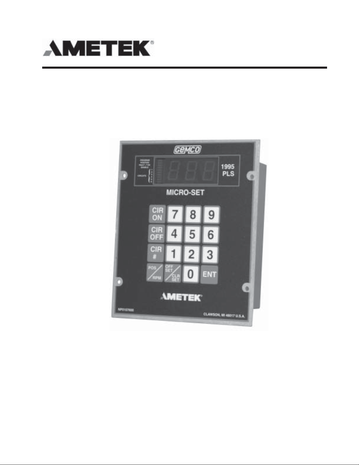
Series 1995A
Gemco
Micro-Set Programmable Limit Switch
®
Installation & Programming Manual
Page 2

1080 North Crooks Road
Clawson, MI 48017-1097
Phone: (248) 435-0700
FAX: (248) 435-8120
Internet: www.ametekapt.com www.ametek.com
Preface
This manual is for the Installation and Maintenance of the Gemco Series 1995A Micro-Set Programmable
Limit Switch.
Copyright 2000 by AMETEK
All Rights Reserved - Made in the U.S.A.
Version 0.1
AMETEK has checked the accuracy of this manual at the time it was printed. Any comments you may
have for the improvement of this manual are welcomed.
AMETEK reserves the right to revise and redistribute the entire contents or selected pages of this
manual. All rights to the contents of this manual are reserved by AMETEK.
iInstallation & Maintenance Manual
Page 3

Contents
Chapter 1: Introduction/Description 1
1.1 Programmable Features ....................................................................................................... 1
1.2 General Information ............................................................................................................. 1
1.3 Controller Features and Functions ........................................................................................ 2
Chapter 2: Installation 3
2.1 Mechanical Installation ......................................................................................................... 3
2.2 Electrical Installation ............................................................................................................ 4
2.3 Wiring Instructions ............................................................................................................... 4
Chapter 3: Programming 5
3.1 Security Input ...................................................................................................................... 5
3.2 Initialization.......................................................................................................................... 5
3.3 Scale Factor ........................................................................................................................ 5
3.4 Number of Outputs.............................................................................................................. 6
3.5 Selecting Number of Outputs ............................................................................................... 6
3.6 Multiprogram (Available Only on P Option Units) .............................................................. 6
3.7 Setpoint Formula ................................................................................................................. 7
3.8 Setpoints ............................................................................................................................. 8
3.9 Clear an Existing Setpoint .................................................................................................. 10
3.10 Clear All Setpoints............................................................................................................ 10
3.11 Setpoint Availability ........................................................................................................... 10
3:12 Electronic Offset ............................................................................................................... 11
3.13 Reset-to-Preset ................................................................................................................ 11
3.14 Motion Detector ............................................................................................................... 12
3.15 Power-Up in a Position or RPM ....................................................................................... 13
3.16 Decimal Point Programming .............................................................................................. 13
3.17 Enable/Disable Outputs..................................................................................................... 14
3.18 Linear Speed Offset (Available Only on Option P Units .................................................. 14
3.19 Programming 1995 PLS for Linear Speed ......................................................................... 16
3.20 Minimum Speed Disable ................................................................................................... 16
3.21 Time-Based Outputs (Available Only on Option P Units) ................................................ 17
Chapter 4: Expansion Modules 18
Chapter 5: Fault Check 19
5.1 PLS Output Status on Fault Conditions ............................................................................... 20
Installation & Maintenance Manualii
Page 4

Chapter 6: Security Inputs 21
Chapter 7: Remote Circular Display 22
7.1 POS/RPM On Remote Circular Display ............................................................................. 22
Chapter 8: Troubleshooting 23
8.1 Preliminary Checks ............................................................................................................ 23
8.2 Transducer Excitation Voltages ........................................................................................... 23
8.3 Electrical Noise and Power Quality Consideration .............................................................. 24
8.4 Grounding ......................................................................................................................... 24
8.5 Incoming Power ................................................................................................................ 24
8.6 Low Level Inputs............................................................................................................... 24
Chapter 9: Specifications 26
9.1 1995 Micro-Set PLS Programmer ..................................................................................... 26
9.2 Mechanical Relay (Single Pole, Double Throw) .................................................................. 26
9.3 AC Solid-State (Single Pole, Normally Open) .................................................................... 26
9.4 DC Solid-State (Single Pole, Normally Open) .................................................................... 27
9.5 1995E Output Expansion Module ...................................................................................... 27
9.6 1995-1446 Remote Circular Display .................................................................................. 27
Chapter 10: Troubleshooting Guide 28
Chapter 11: Wiring Diagrams 31
iiiInstallation & Maintenance Manual
Page 5

Chapter 1: Introduction/Description
Chapter 1: Introduction/Description
The 1995A Micro-Set is a fully self-contained, single-turn resolver-based programmable limit switch.
It includes a three-digit LED display, six output relays, and one fault check relay, and it is fully programmable for the following features:
1.1: Programmable Features
Scale Factor Two scale factors to choose from either 360 or 1,000. On units
with P option software, the scale factor is permanently set to
360.
Electronic Offset Fully programmable offset to any number with the scale factor.
Reset-to-Preset Reset value is programmable to any number within the scale factor.
Motion Detector LS6 can be programmed for either limit switch or motion detect
output.
Expansion Outputs Programmable to accommodate up to 30 circuits.
See Section 1.2: General Information - Software Option P for more options.
1.2: General Information
The 1995A Micro-Set is a fully self-contained, microcomputer-based Programmable Limit Switch
(PLS) with a convenient keypad for programming each independent output circuit to open or close at
the desired settings. This system allows precise position control of rotary motion.
A 1995A consists of a resolver-based transducer, resolver-to-programmer cable assembly, and the
programmer, which provides six limit switch outputs and one fault check output. The optional output
expansion modules will add six additional limit switch outputs per module, and up to four expansion
modules can be driven by the programmer, for a total of thirty limit switch outputs.
The single-turn resolver transducer generates a ratiometric analog signal representing an absolute rotary
position. This ratiometric signal is converted to a digital signal at the Micro-Set. A microprocessor
calculates and/or converts these signals based on user-programmed data.
As the transducer passes through the preprogrammed dwell settings, the programmer outputs can
energize solenoids, relays, or solid-state circuitry to control external circuits.
The 1995A PLS was designed for use in rotary and/or rotary-to-linear applications. It incorporates
many features for safe, efficient operation.
Installation and Maintenance Manual
1
Page 6

Chapter 1: Introduction/Description
The completely self-contained unit can operate up to 30 independent outputs (six standard) based on
the rotary position of the resolver.
It offers an on line fault check which provides an automatic, in-process mechanism to verify that all
major programmable limit switch functions are operating properly. The fault check output can be
energized by activating the fault check enable input. The output is a mechanical relay with 1 N.O. and 1
N.C. contact, which remains energized during normal operation.
A programmable motion detect output will energize a relay when the transducer speed meets or
exceeds the customer-preprogrammed RPM value.
SOFTWARE OPTION P ENHANCES THE SYSTEM BY OFFERING:
n Multiple Programs - Allow storage of job setups for future use. This saves time
spent reprogramming and lessens the chance of programming errors when tooling is
changed.
n Speed-Induced Offsets - On many variable speed machines, the limit switch outputs
have to be adjusted when the speed increases or decreases. This option automatically
adjusts specified circuits based on speed.
n Time-Based Outputs - Specified outputs can be programmed to turn on based on
position and turn off based on time (0.01 - 9.99 seconds).
1.3: Controller Features and Functions
The controller is housed in an all metal case that can be panel mounted. The controller consists of a
keypad, a CPU Board, and a Power Supply I/O Board.
The following features are found on the 1995A Micro-Set.
n Display A (3) three-digit LED readout and a 10-place bar graph are provided.
The LED readout displays current angular position and/or RPM and
programming details, while the bar graph shows fault check, program
status, and limit status.
NOTE: The Bar graph will not display expansion board relay status.
n I/O Mechanical relays, AC solid-state, and DC solid-state relays are
available, and any combination can be specified. The example in the
catalog shows three AC and three DC solid-state relays being specified. There is a fixed price adder for any combination of relays other
than all mechanical (6M). The fault check relay will always be a
mechanical relay regardless of the type of output relays specified.
See Chapter 9: Specifications.
2
Installation and Maintenance Manual
Page 7

Chapter 2: Installation
Chapter 2: Installation
This section describes the installation and wiring of a standard 1995A Micro-Set PLS. Changes to
these instructions should be made as necessary if special options and/or equipment are used.
The 1995A Micro-Set should be installed in an area free of water spray, corrosive gases, flying chips
or other foreign matter. The operating temperature should be between 32 and 125 degrees Fahrenheit,
with less than 95% relative humidity.
2.1: Mechanical Installation
Mounting the 1995 Micro-Set PLS
The 1995A Micro-Set PLS is designed to be panel mounted. The face of the 1995A can be affected
by water and/or oil spray. Provisions should be made to protect the face of the unit from spraying or
splashing.
Panel cutouts, mounting holes, and sizes for each component are shown on Pages 6 and 7 of the 1995A
catalog section.
The controller should be mounted in the appropriate panel cutout and securely bolted into place using
the four (4) 3/16" diameter mounting holes.
NOTE: In instances where the 1995A is being mounted directly on a mechanical stamping press, care
should be taken to isolate the controller from shock load and vibration.
It is always good design practice to mount the controller in the enclosure as far away from the motor
starters and control relays as possible to minimize the effects of electromagnetic interference (EMI).
Interconnecting wiring also should be routed to minimize EMI coupling.
Mounting the Transducer
The transducer should be mounted securely to the machine in such a manner so as to minimize shock
and vibration. The transducer should be coupled to the moving machine member, thus reducing
excessive axial and radial loads. Coupling methods should minimize backlash and be in accordance
with the system accuracy required.
Installation and Maintenance Manual
3
Page 8

Chapter 2: Installation
2.2: Electrical Installation
The Micro-Set is designed for use in an industrial environment and incorporates extensive transient
suppression circuitry. However, the same general installation rules should be followed that are used on
all microprocessor-based equipment. Incoming AC lines should be from a clean power source and
lines carrying computer level signals should not be routed in the same conduit as high voltage, transientproducing circuits such as variable speed drives, welders or DC switching circuits.
The 1995A PLS is only used with a single-turn resolver. Wiring for this system is shown in Fig. 11-3,
Chapter 11: Wiring Diagrams. This wiring diagram is applicable for all standard 1995 PLSs.
2.3: Wiring Instructions
Attach the pre-wired plug on the resolver transducer cable to the transducer and route the shielded
cable through a separate grounded (earth ground) metal conduit to the panel. Connect the mating half
terminal block to the 1995A PLS. Be sure the shield wire is connected to Pin 1 of the 16-place
connector.
When extension to the factory supplied cable is necessary, a junction box should be used to connect the
wire leads and the cable shields from one cable to the other. The cable shield should be grounded at the
1995 Micro-Set only.
AC line voltage - 115V AC + 10% 50-60 Hz - should be connected to the 1995A PLS at the AC
power terminals on the 24-place connector.
4
Installation and Maintenance Manual
Page 9

Chapter 3: Programming
Chapter 3: Programming
3.1: Security Input
The security input is often referred to as the Run/Program input. This input is located on the 16-place
terminal strip and is discussed in Chapter 4: Expansion Modules. This input prevents unauthorized
changes to the programmed functions. With the unit in the Program mode, all functions of the controller can be programmed. With the unit in the Run mode, all setpoints, reset-to-preset, motion detect
and other operational functions can be verified, but the programmed information cannot be changed.
3.2: Initialization
The following key commands should be entered on the
keypad to clear all programmed data upon installation and PRIOR to programming. This sequence
clears all programmed data. All operating parameters must be reprogrammed after using this initialization function.
CIR#- 9- 9 5
--
ENT
3.3: Scale Factor
NOTE: Programming of the desired scale factor or the number of outputs will delete all programmed
data held in memory. Therefore, these should be the first steps in your setup procedure.
The 1995A is available with two scale factors: 360 or 1,000.
To program the scale factor, the following procedures must be followed:
1) Unit must be in the Program mode.
2) Depress
CIR#- 3- 6 0
-or-
CIR#- 9- 9 9
--
--
ENT
ENT
NOTE: ON UNITS WITH SOFTWARE OPTION P, THE SCALE FACTOR IS
PERMANENTLY SET AT 360.
Installation and Maintenance Manual
5
Page 10

Chapter 3: Programming
3.4: Number of Outputs
The 1995A comes programmed for six outputs, but it is expandable to 30 outputs. However, when
using a Remote Circular Display, the maximum will be 24 outputs.
3.5: Selecting Number of Outputs
Selection of the number of outputs should be done after the desired scale factor is entered, and before
any other programming is done. See Chapter 4: Expansion Modules.
A) To program the number of outputs desired, the unit must be in the Program mode, then depress
. The unit will then show the number of circuits previ-
CIR#- 1- 7 7
ously stored. To change the number of outputs desired, enter the number of relays in multiples
of six and depress .
--
ENT
ENT
1) Valid numbers for are and
. Remember, if using a Remote Circular Display, the maximum number of
30
outputs is 24.
NOTE: If a number is entered that is not a multiple of six, the unit will store the next multiple of six.
CIR#- 1- 7 7
--
ENT
6 12 24 18
,,,,
3.6: Multiprogram (Available Only on P Option Units)
The Multiprogram feature allows the storage of multiple sets of output sequences that are
preprogrammed based on the various requirements of different tooling. When dies or tooling are
changed, the new program is simply called up on the keypad and all outputs are automatically set to the
new output sequences. The number of available programs will vary based on the number of output
limits and the number of setpoints programmed on each limit. A typical six-limit system with one ON
and one OFF setpoint per output will be capable of storing twenty programs in memory
A setpoint is one CIR ON or CIR OFF entry. The following formula shows the relationship
between the number of output relays, the number of programs, and the number of setpoints available
per program.
6
Installation and Maintenance Manual
Page 11

3.7: Setpoint Formula
Setpoint/Programs = 1467 - 2
Number of Programs x A
Where: A = 5 for 6 outputs
= 6 for 12 outputs
= 7 for 18 outputs
= 8 for 24 outputs
= 9 for 30 outputs
Setpoints are in whole numbers (drop decimal).
Example: 12 outputs relays with 10 programs:
S.P. = 1467 -2 = 24.45 - 2 = 22 Setpoints/Program
10 x 6
Chapter 3: Programming
The following table shows the relationship between the number of outputs, the number of programs, and
the number of setpoints per program. The table only shows a few of the many combinations that are
possible. Before programming outputs, it is advisable to verify that enough setpoints are available, otherwise
the number of programs may need to be reduced. A setpoint is one CIR ON or CIR OFF entry.
STUPTUO6STUPTUO21STUPTUO81STUPTUO42STUPTUO03
352/1242/1702/1181/1161/1
21/0252/993/534/497/2
9/6281/2142/843/525/3
6/6321/7181/0142/703/5
1/797/7241/3102/852/6
Number of program Resulting in number of setpoints per program.
Programming 1995 PLS for Multiprogram
A) Specify the number of programs desired, unit must be in the Program mode. Depress
See above table
CIR#- 7- 7 0
for the capabilities of your unit.
äã
-- CIR ON
ENT
-
- ENT-
# of Programs
.
B) Upon entering the above sequence, depressing the key will display the
maximum amount of setpoints per program.
NOTE: A time-based output uses up three setpoints.
Installation and Maintenance Manual
CIR OFF
7
Page 12

Chapter 3: Programming
C) will display the total number of setpoints available for use in
D) To display the active program, depress .
NOTE: Program 0 is the first program. If 10 programs were previously selected using Code 770,
CIR# 7- 7- -2 ENT-
the currently selected active program.
CIR# - 7 To change programs, with the unit in the Program mode, depress
.
(0 thru Highest Program Number)
there will be programs 0-9.
-
ENT
7 1
-
ENT-
3.8: Setpoints
Programming New Setpoints
A) Unit must be in the Program mode.
B) Select a limit switch circuit for programming. Depress .
The circuit number selected cannot exceed the number of output relays specified earlier using
CIR# 177. See Section 3.5: Selecting Number of Outputs.
CIR#
--(1 thru 30) -
ENT
-
C) Depress . The will set the selected relay turn-on
point.
D) Depress . . This will set the selected relay turnoff
point.
1) On units where time-based circuits have been selected, the will be the
E) Multiple ON and OFF setpoints can be programmed on each circuit. All decimal points will
flash when more than one setpoint exists on the selected circuit.
F) An LS (Limit Switch) may not have the same value for both the ON point and the OFF point.
If a value is entered that is already a setpoint for that LS, only the new one will be used. For
example: If LS1 had an ON point at 100 and an OFF point of 100 was entered, the ON point
at 100 would be deleted, and the OFF point would then take its place. Assuming that these
were the only setpoints, the output would turn ON at 0 and OFF at 100.
The programmable limits are programmed based on dwell on and dwell off locations. The dwell
on typically represents the location at which a selected limit turns on and the dwell off represents the
location at which the limit turns off. The position locations for the dwell on and dwell off are based
CIR ON- (Desired Pos)
CIR OFF- (Desired Pos)
time interval that the relay will be active once the ON setpoint has been reached.
ENT
ENT
CIR OFF
8
Installation and Maintenance Manual
Page 13

Chapter 3: Programming
on a scale factor corresponding to the 360-degree rotation of the resolver. Example: In the foregoing
example, with a 360 scale factor, a dwell on of 0 and a dwell off of 100 would look like this:
0
The shaded area represents the area where the selected limit output relay is energized. Programmable
limit switch outputs offer a unique function which normal rotating cam limits cannot, namely, the ability to
turn a limit on or off more than once in a 360-degree cycle. Multiple dwells allow several dwell on
and dwell off values to be programmed for a particular limit. Example: Dwell on settings of 20,
100, 200, and dwell off settings of 80, 180, 270 would look like the following:
100 359
0 20 80 100 180 200 270 359
Another feature of programmable limits is the ability of programming a dwell on or a dwell off only.
If only a dwell on setting is programmed, the output will activate at the dwell on setting and remain
on to 359 degrees. Example: Dwell on setting of 180 and dwell off not programmed will result in
the following:
0 180
Conversely, if only a dwell off setting is programmed, the output will activate from 0 degrees to the
dwell off setting. Example: Dwell on not programmed, dwell off set at 180 degrees will result in
the following:
359
0 180 359
The programmable limits also have the ability to shift the dwells to turn on sooner. This can be done
to compensate for mechanical lag in the devices they are controlling as the machine speed increases.
(See Section 3.18: Linear Speed Offset for more details). Limits can also be programmed to turn off
based on timed settings.
Installation and Maintenance Manual
9
Page 14

Chapter 3: Programming
3.9: Clear an Existing Setpoint
A) Unit must be in the Program mode.
B) Depress .
C) Depress or key until setpoint to be cleared is on the display.
D) Depress the key. Upon depression of the key, the setpoint on
the display after Step C is deleted.
E) This keypad sequence must be completed once to clear an ON setpoint and a second time to
clear the OFF setpoint. See Section 3.8: Setpoints
CIR#
CIR ON
(Output to be Cleared) ENT
CIR OFF
--
CLR SETCLR SET
3.10: Clear All Setpoints
There are two methods of clearing all setpoints. This is accomplished as follows:
A) Unit must be in the Program mode.
B) To clear all of the setpoints in the active program, depress: .
The active program is the program currently selected using Code 771. See Section 3.7:
Setpoint Formula.
CIR#- 9- 1
ENT
-OR-
C) To clear all the setpoints in all programs, depress: .
NOTE: CIR# 91 and CIR# 391 only clear out programmed setpoints. They do not clear out Linear
Speed ramps or change circuits that have been selected as Linear Speed or Time-Based;
however, they will clear the setpoints programmed in these circuits.
CIR#- 3- 9- 1
--
ENT
3.11: Setpoint Availability
Every 1995 PLS has a limit on the number of setpoints that can be stored in memory. On units with the
Multiprogram option, refer to Section 3.7: Setpoint Formula to calculate the maximum amount of
setpoints available.
10
Installation and Maintenance Manual
Page 15

Chapter 3: Programming
On units without Multiprogram, setpoint availability is dependent on the number of outputs enabled.
6 Outputs = 253 Setpoints Available
12 Outputs = 242 Setpoints Available
18 Outputs = 207 Setpoints Available
24 Outputs = 181 Setpoints Available
30 Outputs = 161 Setpoints Available
Refer to the Section 3.5: Selecting Number of Outputs.
3.12: Electronic Offset
The offset key is used to synchronize the digital display with the actual machine position. The Series
1995A PLS has full scale factor offset capabilities, and the offset is held in nonvolatile memory. How-
ever, to eliminate possible problems in the event that a replacement PLS is required, it is good practice
to mechanically synchronize the resolver with the machine and then use the offset key to make final, finetune adjustments.
Programming the Electronic Offset
A) Unit must be in the Program mode.
B) Stop machine at a known location.
C) Depress . After this sequence is
completed, the display will change to the position entered. The display and outputs are now
synchronized with the actual machine position.
OFFSET (Actual Machine Position) ENT
-
-
3.13: Reset-to-Preset
Remote Reset-to-Preset Value - This option allows the position of the PLS to be reset to a keypad
selected value; this value would be based on an input from a remote contact or proximity switch
mounted at a known location on the machine. Typical uses include compensation for slippage of idler
wheel-driven resolvers, cable stretch, gear train backlash, as well as, for synchronizing outputs with the
leading edge of products moving through a machine.
The reset-to-preset function of the 1995A requires an isolated contact closure. The isolated contact is
used as an input to the 1995A PLS; upon closure, it will reset the unit to its preprogrammed reset value.
If an auxiliary contact is available, it can be wired to the 1995A PLS to perform this function. If an
auxiliary contact is not available, a reset input relay (Part No. SD0395100) can be purchased and wired
to a 110V AC circuit to provide this output.
Installation and Maintenance Manual
11
Page 16

Chapter 3: Programming
Programming Reset-to-Preset Value
The Reset-to-Preset Value is programmed by entering the following:
A) Unit must be in the Program mode.
B) The Reset-to-Preset must first be enabled before you can store any values. To accomplish this,
depress . A zero (0) disables a
function and a one (1) enables it.
C) Once the Reset-to-Preset has been enabled, you can store a value in memory. This is accom-
plished by depressing
NOTE: Valid numbers for CIR# 160 are zero (0) through the programmed scale factor, less one (1).
CIR#- 1- 6 6
CIR#- 1- 6 0
--
ENT
-
(0 or 1)
--
ENT
-
ENT
-
(Desired Reset Value)
-
ENT
.
3.14: Motion Detector
A programmable Motion Detect output will energize a relay when the transducer speed exceeds the
customers preprogrammed RPM value.
The motion detector is set by entering the following:
A) Unit must be in the Program mode.
B) The motion detect must first be enabled before you can store any values. To accomplish this,
depress . A one (1) will enable the motion
detect output circuit, and LS6 will now be your motion detect output relay. If a zero (0) is
entered, the motion detect feature is disabled and LS6 will function as a normal limit switch.
C) To set the value at which the motion detect relay energizes, depress
CIR#- 1- 7 6
NOTE: A CIR #176 can only be entered if the motion detect option is enabled.
CIR#- 5- 5
--
-
ENT
ENT
-
(0 or 1)
-
(RPM Value)
-
ENT
-
ENT
.
12
Installation and Maintenance Manual
Page 17

3.15: Power-Up in a Position or RPM
The 1995A can power up displaying either Position or RPM data.
The power-up mode is programmed by entering the following:
A) Unit must be in the Program mode.
Chapter 3: Programming
B) Depress . If a zero (0) is entered,
positional data will be displayed upon power-up; if a one (1) is entered, the unit will power up
displaying RPM.
CIR#- 1- 6 3
--
ENT
-
(0 or 1)
-
ENT
3.16: Decimal Point Programming
A continuous, nonfloating decimal point may be programmed on the display. If a scale factor is selected
that needs a decimal point in order to properly display its resolution in engineering units, the following 50
series codes are used:
50 - No decimal point;
clears existing decimal point 123
51 - Tenths 12.3
52 - Hundreths 1.23
To program a decimal point, enter the following:
A) Unit must be in the Program mode.
B) Depress .
Example: CIR# 50 = 123
CIR#- 50or 51 52
CIR# 51 = 12.3
CIR# 52 = 1.23
or -
Installation and Maintenance Manual
ENT
13
Page 18

Chapter 3: Programming
3.17: Enable/Disable Outputs
During setup, the outputs may be enabled or disabled. When outputs are selected to be disabled, the
status LEDs and the relays will be OFF. The unit must be in the Program mode to disable the outputs;
as soon as the unit is switched to the Run mode, the outputs will be enabled.
The enable/disable feature is programmed as follows:
A) Unit must be in the Program mode.
-
B) Depress
CIR# 380 Enables the Outputs.
CIR# 381 Disables the Outputs.
NOTE: If you try to disable the outputs in the Run mode, the unit will display EEE.
CIR#
(380 or 381)
-
ENT
.
3.18: Linear Speed Offset (Available Only on Option P Units)
This feature allows limit switch outputs, one through six, to be programmed to automatically advance
and retard as machine velocity varies. The number of circuits affected by speed offset, the amount of
offset, and the RPM range over which the offset develops are all keypad programmable. The amount
to offset per RPM change will be the same for all outputs selected for this type of operation. This
feature is used to compensate for the mechanical lag in machine controls.
The 16-step linear speed offset feature allows up to 16 different offset steps to be selected and a
different amount of positive or negative (advance or retard) offset to be programmed between each of
the sixteen steps.
Access Codes 501 through 516 are used to select the successive steps that define a ramp between the
various offset values. That is, Code 501 is used to access and program the ramp between 0 RPM and
the RPM value assigned to the first step; Code 502 is used to access and program the ramp between
the RPM value of the first step and the RPM value assigned to the second step; and so on.
After using the access code to call up a step for programming, the CIR ON key is depressed, followed
by the total amount of offset (from zero offset) to be applied to the circuit at the specified RPM value.
The CIR OFF key is depressed next, followed by the RPM value of that step. The programmed offset
value will be the total amount of offset being applied to the circuits from their zero offset starting values.
This allows the circuits to be advanced or retarded between any two steps. See Section 3.19:
Programming 1995 PLS for Linear Speed.
14
Installation and Maintenance Manual
Page 19

Chapter 3: Programming
The graph above shows an example of four steps of linear offset in which the output circuits are being
advanced in the first two steps, retarded between the second and third, and remaining unchanged
between the third and fourth. The first step (501) is programmed to linearly advance the selected
outputs by 20 degrees between 0 and 60 RPM. Circuits originally programmed to turn on at 150
degrees and off at 350 degrees will be turning on at 130 degrees and off at 330 degrees while at 60
RPM. The second step (502) is programmed to advance these same outputs to a total of 50 degrees
as RPM rises between 60 and 100 RPM. The example circuit mentioned above that was originally
programmed to turn on at 150 degrees and off at 350 degrees will now be turning on at 100 degrees
and off at 300 degrees while at 100 RPM. The third step (503) is programmed to retard the circuits
back to a total of 30 degrees as RPM continues to rise from 100 to 140 RPM. The example circuit,
originally programmed to turn on at 150 degrees and off at 350 degrees is now turning on at 120
degrees and off at 320 degrees while running at 140 RPM. The fourth step (504) is programmed to
maintain a fixed 30 degrees of total offset between 140 and 200 RPM.
NORMAL PLS DWELL
0 150 350 359
1ST COMPENSATION AT 60 RPM
0 130 359330
2ND COMPENSATION AT 100 RPM
0 100 300 359
3RD COMPENSATION AT 140 RPM
0 120 320 359
4TH COMPENSATION AT 200 RPM
0 120 320 359
The offset (advance or retard) is applied linearly between each step, and the offset follows the same
curve as RPM decreases. Example: At 80 RPM, offset value would be 35°.
Installation and Maintenance Manual
15
Page 20

Chapter 3: Programming
3.19: Programming 1995 PLS for Linear Speed
A) Unit must be in the Program mode.
B) Select the number of circuits that will be offset based on RPM. The affected circuits will always
start with CIR# 1 and will follow in ascending sequence to the number specified. Depress:
CIR#
NOTE: LS6 cannot be programmed for Linear Speed if it is set for Motion detect. See Section 3.14:
NOTE: On units built prior to June 1, 1992, the Linear Speed Offset had only a single ramp offset.
C) Starting with Circuit 501, program the amount of offset and RPM point for the first offset ramp.
Next use Circuit 502 to program both values for the second offset ramp. Continue with Circuit
503 and onward in ascending order until all desired ramps are programmed.
-
Motion Detector
CIR# - 81 - ENT - CIR ON = Offset Amount
CIR# - 81 - ENT - CIR OFF = RPM Value
Codes 501 - 516 will result in a programming error on this older software.
80
-
ENT
- -
(1 thru 6)
ENT
CIR#- 501 thru 516
1)
from the original output settings) -
2)
CIR#- 501 thru 516
above specified amount of offset occurs.)
NOTE: If CIR# 501 - CIR OFF is set to zero, all linear speeds will be disabled.
-
ENT
- CIR OFF-
ENT
-
CIR ON
ENT..
-
(Specify the total amount of offset
-
(Specify the RPM at which the
3.20: Minimum Speed Disable
The Minimum Speed Disable sets the minimum speed at which the Linear Speed will affect the outputs.
Below the programmed speed, the Linear Speed outputs will not be enabled.
The Minimum Speed feature is programmed as follows:
A) Unit must be in the Program mode.
B) Depress . This sets the Minimum Speed at
which the Linear Speed will affect the outputs. Below the programmed speed, the Linear
Speed outputs will not be enabled.
16
CIR#
-
85
-
ENT
-
(RPM Value)
Installation and Maintenance Manual
-
ENT
Page 21

Chapter 4: Expansion Modules
Chapter 4: Expansion Modules
The 1995A PLS provides six outputs. A 1995E Expansion Module is required for each additional six
outputs desired, up to a total of 30 outputs, or four expansion modules (units with Remote Circular
Displays may use only up to 24 outputs total, or three expansion modules). The circuit location of
each expansion module is defined by the location of a two-pin jumper on an eight-pin block in the upper
left corner of the module. This jumper must be installed for the expansion module to operate. Two
pairs of pins, located in the lower right corner of the expansion module, should be jumpered on only the
last module in the wiring group. However, if a Remote Circular Display is being used, do not install
these jumpers. Remove both jumpers from all intermediate expansion modules. See Chapter 11:
Wiring Diagrams, Fig. 11-2 for additional expansion module wiring information. Each expansion module
is provided with a full set of terminal strip designation decals. To avoid confusion, the appropriate
decals should be installed along the output terminals, based on the location of the output selection
jumper outlined below.
Fig. 4-1
See Section 3.5: Selecting Number of Outputs, for instructions on how to program unit for use with
expansion modules.
18
Installation and Maintenance Manual
Page 22

Chapter 3: Programming
3.21: Time-Based Outputs (Available Only on Option P Units)
These outputs are programmed to turn on based on position and turn off based on a keypad selectable
time interval. Circuits one through six can be selected for this type of operation. Circuits cannot be
programmed for Linear Speed Offset and Time-Based outputs at the same time; thus the total
combined number of Linear Speed Offset and Time-Based outputs cannot exceed six.
NOTE: CIR# 301 thru 306 only enable the circuit so that it can be programmed for a Time-Based
output. After Time-Based circuits are enabled, see Section 3.8: Setpoints.
The Time-Based feature is programmed as follows:
A) Unit must be in the Program mode.
B) Depress
CIR#- (301 thru 306)
-
-
(0 or 1)
- ENT ENT .
CIR# 301 represents CIR# 1, CIR# 302 represents CIR# 2, etc. A zero (0) after CIR# 301306 means that the circuit will function as a normal limit switch as outlined in Section 3.8:
Setpoints; however, if a one (1) is entered in after CIR# 301-306, it means that the circuit is to
be set up for a position ON and a timed OFF output.
C) This sequence only enables or disables LS1 thru LS6 for Time-Based operation. After an LS
is enabled as a Time-Based circuit, follow normal programming instructions. See Section 3.8:
Setpoints, C and D.
NOTE: If LS6 is set as a motion detector, it cannot be set for Time-Based.
D) A Time-Based output may only have one CIR ON and one CIR OFF setpoint. This output
will turn on based upon the CIR ON position data and will turn OFF based upon the CIR OFF
time data, which is displayed and programmed in 0.01 second increments. A Time-Based
output uses three setpoints. See Section 3.7: Setpoint Formula.
E) Outputs 1 through 6 may incorporate Linear Speed Offset or may be Time-Based. How
ever, no output can be both. In addition, LS6 may be selected to be a motion detect output. If
two or three types of outputs are required, first select the number of Linear Speed circuits
required (CIR 80) and then individually select the Time-Based outputs and Motion Detect
output.
Example: Outputs 1 & 2 Linear Speed
CIR = 80 - ENT - 2 - ENT
Outputs 3 & 4 Time-Based
CIR = 303 - ENT - 1 - ENT
CIR = 304 - ENT - 1 - ENT
Output 6 Motion Detect
CIR = 55 - ENT - 1 - ENT
Installation and Maintenance Manual
17
Page 23

Chapter 5: Fault Check
Chapter 5: Fault Check
The Fault Check option provides an automatic in-process self-diagnostic mechanism to verify that all
PLS functions are operating properly.
The Fault Check option will detect and disable system operation in the event of any of the following
problems:
1. Disconnect or severed resolver cable.
2. Open or shorted resolver signals.
3. Resolver excitation failure.
4. Resolver-to-digital converter or associated electronic failure.
5. Microprocessor or 5 volt power supply failure.
Non-system-type faults, such as individual output failures, will not be sensed. It is recommended that
the Fault Check output be used as an operate enable type signal. Loss of this output should immediately stop the process which is being controlled.
The Fault Check input may be operated by an isolated contact, current sourcing, or current sinking
device 5V DC at 10mA.
A normally closed, momentary open contact button can be wired per Fig 11-3, Chapter 11: Wiring
Diagrams, to activate the Fault Check circuit, and it will provide a method of resetting the fault output
after a fault condition has been sensed.
To reset the Fault Check output after the fault condition has been cleared, the fault reset input must be
deactivated (open circuit) and then re-actuated. Cycling the fault reset input will cycle the fault check
relay to verity that the Fault Check output is operating properly.
NOTE: If the Fault Check inputs are not wired, the display will still show when there is a fault and the
outputs will be disabled, but it will not lock on the fault. However, if the fault check inputs are
wired as per Fig 11-3, Chapter 11: Wiring Diagrams, then upon seeing a fault, the fault check
relay will drop out and all outputs will shut off until the fault is fixed and the fault check input is
reset.
Installation and Maintenance Manual
19
Page 24

Chapter 5: Fault Check
5.1: PLS Output Status on Fault Conditions
1) If a fault condition is detected, ALL limit switch outputs will turn off and the display will
show the following:
EE0 = Resolver Not Plugged in or Resolver Primary Open
EE1 = Resolver Secondary S1-S3 Open or Shorted
EE2 = Resolver Secondary S2-S4 Open or Shorted
EE3 = Resolver Shorted - Primary Winding or Resolver Excitation Fault
EE4 = Electronic Transducer Tracking Fault
No Message Microprocessor or 5 Volt Power Supply Failure
The message will remain on the display and the outputs will be off until the problem is
corrected and the fault reset button is pressed and released to reactivate the fault output
and return the display and outputs to their normal operation.
2) If the fault condition is the result of a microprocessor failure or lockup, the state of the
limit switch output circuits cannot be predicted. However, the fault check output will
turn off until the fault is cleared and the fault reset button is pressed and released.
Removal and reapplication of power to the PLS system may clear a locked-up
condition.
20
Installation and Maintenance Manual
Page 25

Chapter 6: Security Inputs
Chapter 6: Security Inputs
The Run/Program security inputs may be operated by an isolated contact, current sourcing, or a current
sinking device, 5V DC @ 10mA. See Fig 11-3, Chapter 11: Wiring Diagrams.
NOTE: The 1995 PLS cannot be programmed until the security input has been actuated by means of
connections between +5V DC and Security + input and between Security - input and
ground.
NOTE: If the Run/Security program is not needed (always in the Program mode) install jumper wires
form Pin 9 (+5V DC) to Pin 10 (Security +) and from Pin 11 (Security -) to Pin 14 (GND)
on the 16-place resolver connector.
Installation and Maintenance Manual
21
Page 26

Chapter 7: Remote Circular Display
Chapter 7: Remote Circular Display
The Remote Circular Display (1995-1446) is ideal for mechanical stamping presses and shears.
Either position or RPM can be displayed on the large 3/4 LED digital display. A 360° bar graph will
increment in 10° intervals showing the angle of the resolver.
The remote circular display gets its RS422 synchronous signal from the four-place terminal strip located
on the back of the 1995 programmer. The display can be located up to 1,000 feet away from the
programmer. See Fig 11-2, Chapter 11: Wiring Diagrams.
Installation and wiring of the remote circular display should be followed in the same manner as the
1995A described earlier in Chapter 2.
NOTE: When using a remote circular display, the maximum number of outputs is limited to 24 outputs
or three expansion boards.
7.1: POS/RPM On Remote Circular Display
The 3/4 LED display can display either position or RPM while the bar graph will always show angular
position. To display RPM install a jumper wire from Pin 6 (RPM) to Pin 7 (GND) on the 11-place
connector located on the bottom of the remote circular display.
22
Installation and Maintenance Manual
Page 27

Chapter 8: Troubleshooting
Chapter 8: Troubleshooting
The following procedures are intended to aid in isolating system malfunctions to field replaceable
modules. These modules include the 1995 programmer, output relays, remote circular display, transducer, and all interconnecting cables. Once isolated, the defective module should be replaced and
returned to the factory for repair.
NOTE: Field repair beyond this level is not recommended.
8.1: Preliminary Checks
Check all system wiring connections at the transducer and at the programmer. Amphenol-type connectors on the transducer and its cabling should be checked for tightness. A slight tug on all wire terminations should verify a good connection. Push-on cable connectors should be checked for proper connections. Verify that incoming AC voltage to the 1995 PLS is between 105V AC and 125V AC.
8.2: Transducer Excitation Voltages
AC voltage across terminals 2 (RH) and 3 (RL) of the 16-place terminal strip (labeled Red and BK/R)
should be from 1.6 to 1.9V RMS. This is the output voltage being supplied to the resolver rotor. If this
voltage is not present, disconnect the resolver wires at the 1995 programmer and recheck the voltage.
If this voltage is still not present, the resolver excitation circuitry in the 1995 programmer has failed and
should be replaced. If this voltage appears, a shorted condition in the resolver or its cable should be
checked.
The return signals from the resolver stator windings are wired to the 1995 programmers 16-place
terminal strip at terminals 4 and 5 (labeled White and BK/W), and terminals 6 and 7 (labeled Green and
BK/G). To verity the presence of these AC return signals, put a voltmeter across terminals 4 and 5 and
rotate the resolver. A voltage reading that rises and falls (0-2.3V RMS) between these terminals as the
resolver is rotated indicates a good resolver return signal. Repeat this same procedure with your meter
across terminals 6 and 7. No voltage or a voltage that does not vary as the resolver rotates indicates an
open or shorted condition in the resolver windings or the resolver cable.
To check for an open or shorted condition inside of the resolver, disconnect the Amphenol-style connector from the transducer and make the following checks at the resolver: Measure the resistance
across Pins A & B (rotor); it should measure approximately 19-50 ohms. Then measure across Pins C
& D (stator); it should measure approximately 50-120 ohms. The resistance across E & F should be
the same as C & D.
NOTE: Due to the many different types of resolvers that we have used over the years, these
resistance readings are only approximate and are intended for locating opens or shorts in the
resolver wires or windings.
Installation and Maintenance Manual
23
Page 28

Chapter 8: Troubleshooting
8.3: Electrical Noise and Power Quality Consideration
The 1995 PLS is designed for use in an industrial environment and incorporates extensive transient
suppression circuitry. However, the same general installation rules should be followed that apply to all
microprocessor-based equipment.
Problems that can be attributed to extreme electrical noise or poor power quality include loss of/or
changes in program memory, loss of initialization, keypad or microprocessor lockup, sporadic outputs,
and damage to resolver drive circuits and auxiliary input circuits.
8.4: Grounding
Circuit board level noise suppression circuits, ground planes, and cable shields all depend on a good
earth ground for proper operation. Our field experience has shown that the quality of the service
ground at many machines is marginal.
8.5: Incoming Power
Solenoids, welders, large motors, and variable-speed drives are all devices that generate excessive
electrical noise throughout the power grid in a typical industrial environment. Isolation transformers or
constant voltage type power supplies should be used to isolate microprocessor-based circuitry. The
power on the output side of these isolation devices should be fed to the programmable limit switch and
other microprocessor-based devices only. The loads being driven by the programmable limit switch
output relays must not get their power from the output side of the isolation device. Using the output
side of an isolation device to power loads other than the programmable limit switch totally defeats the
purpose of the isolation device.
NOTE: When using an output relay for driving inductive loads such as solenoids, a noise suppression
device must be installed across the coil of the load. Use an MOV or RC noise suppressor
for AC loads, or a commutating diode for DC loads.
8.6: Low Level Inputs
Low level inputs to the 1995A PLS include the resolver cable and other special purpose contact inputs
such as reset-to-preset, fault check, and security.
The resolver should be wired to the 1995 PLS using an uninterrupted run of cable consisting of four
twisted pairs with shields. Whenever possible, this cable should be run in a conduit by itself. If it must
run in a conduit with other wiring, this wiring should not include power wires above 110V AC or wires
driving noise producing loads.
24
Installation and Maintenance Manual
Page 29

Chapter 8: Troubleshooting
If the resolver cable must be run through a terminal strip, it must be mounted in a small enclosure with no
other wiring. The shields of the incoming and outgoing cable must be tied together and isolated from
ground.
Special purpose contact inputs all operate by connecting the input pin on the 1995 PLS to a power or
GND terminal (depending on method wired per Fig. 11-3; Chapter 11: Wiring Diagrams) on the 1995
PLS through a remote contact or solid-state switch. These computer level signals must be protected
from induced electrical noise.
The contact used to activate the input should not be located outside the enclosure in which the 1995
PLS is mounted. Any wiring between the 1995 PLS input terminals and this contact located within the
enclosure should be routed away from any power handling relays, contactors, or other noise generating
devices.
If the input is to be activated by a remote device, the contact of the remote device should be used to
energize a relay within the enclosure. The contacts of this relay are wired to the 1995 PLS input
terminals.
Installation and Maintenance Manual
25
Page 30

Chapter 9: Specifications
Chapter 9: Specifications
9.1: 1995 Micro-Set PLS Programmer
Resolution -12 Bit (4096)
Scale Factor -360 or 1,000
Scan Time -Standard 285 µseconds
Temperature -32°F to 125°F (Operating)
Range -0°F to 150°F (Storage)
Operating Voltage -110/120V AC 50/60 Hz 300 mA
INPUTS
Transducer -Resolver accurate to ±3 arc minutes provides resolution of 1
part in 4096, 2800 RPM maximum speed.
Logic -Fault check and security 5V DC at 10mA. May be operated
by isolated contact, current sourcing or current sinking device.
OUTPUTS -Plug-in relays listed below
9.2: Mechanical Relay (Single Pole, Double Throw)
Contact Relay -10 Amp Isolated Contact
Pick-Up -2 ms
Drop-Out -15 ms
9.3: AC Solid-State (Single Pole, Normally Open)
Maximum Load -1 Amp
Load Voltage Range -70 - 250V AC Zero Voltage Switching
Leading Current -3 mA at 120V AC
Voltage Drop w/Output On -3.0V RMS or Less
Inputs -N.O. and Common
Operate & Reset Time -1/2 cycle of line voltage max. +1ms or less
26
Installation and Maintenance Manual
Page 31

9.4: DC Solid-State (Single Pole, Normally Open)
Maximum Load -2 Amp DC
Load Voltage Range -5 to 60V DC
Leakage Current -2 mA Maximum
On State Voltage Drop -1.5V Maximum
Surge Current -5A (1 Sec. Maximum)
Min. Operational Current -50 mA
Operate Time -0.5ms Maximum
Reset Time -2 ms Maximum
9.5: 1995E Output Expansion Module
Operating Voltage -110/120V AC 50/60 Hz 100 mA
Temperature Range -32°F to 125°F (Operating)
0°F to 150°F (Storage)
Outputs -Same as Programmer
Chapter 9: Specifications
9.6: 1995-1446 Remote Circular Display
Operating Voltage -110/120V AC 50/60 Hz 150 mA
Temperature Range -32°F to 125°F (Operating)
0°F to 150°F (Storage)
Installation and Maintenance Manual
27
Page 32

Chapter 10: Troubleshooting Guide
Chapter 10: Troubleshooting Guide
MOTPMYS SESUACELBISSOP
EEE:swohSyalpsiD ehtnitonsitinuroecneuqesgnimmargorptcerrocnI
stupnIytiruceS:6retpahCweiveR.edommargorp
.noitamrofnimargorP/nuRrof
0EE:swohSyalpsiD
1EE
2EE
3EE
4EE
PPP:swohSyalpsiD.noitazilaitinifossoL
,etarepotonseodyalertuptuolaudividninA
reporpsetacidnidapyeknothgilsutatstub
.noitarepo
.atadsselgninaemsyalpsiddapyeK aeranoitarbivrokcohshgihanidetnuommetsyS
.gnitoohselbuorT:8dnakcehC
rewoperevesasetacidninoitazilaitinifossoL
.yalerecalpeR.deliafevah
.snoitcennoclacirtceletnettimretnignisuac
esionlacirtcelehgihanignitarepometsyS
snoitcurtsninoitallatsniweiveR.tnemnorivne
.noitaredisnoCytilauQrewoP
tluaF:5sretpahCweiveR.tluafadetcetedsahtinU
:8retpahCweiveR.esionlacirtceleronoitautculf
.noitazilaitinI:2.3noitceSdnagnitoohselbuorT
dapyeknoDELsutatsyalerfI.eruliafyalertuptuO
yamyaler,nonrutt'nseodyalerehttub,setarepo
woL:6.8noitceSniselbacfognituorgninrecnoc
esionlacirtcelelarenegweiverosladnastupnIleveL
dnaesioNlacirtcelE:3.8noitceSnisnoitaredisnoc
28
sinottubtesffonehwEEEsyalpsidtinU
.desserped
.snoitcurtsnierawtfoSlatnemelppuS
Installation and Maintenance Manual
sitinuruoyro,edommargorpehtnitonsitinurehtiE
ylnoerehwedocsseccalaicepsahtiwdeppiuqe
otrefeR.metsystesffonaclennosrepdezirohtua
Page 33

MOTPMYS SESUACELBISSOP
Chapter 10: Troubleshooting Guide
astibihxetubylreporpsetarepometsyS
.stuptuollafossolyratnemommodnar
05sanoitarudatrohssarofrewopfossolA
.metsysehtotrewopllafossolyratnemommodnaR
.nwodtuhsotmetsysehtesuaclliwsdnocesillim
ekatnacmetsyseht,deilppaersirewopnehW
emitsihtgniruD.flestiezilaitinierotsdnoceslareves
tnettimretnisihT.delbasiderastuptuolla,doirep
lanimretdabaybdesuacebdluocrewopfossol
afonoitacilppa,tcatnocyalerdab,noitcennocpirts
fossolyratnemomro,daolrotomegralyrev
.rewoptnalpgnimocni
noitazinorhcnysesolstuptuodnayalpsidehT
.noitisopenihcamhtiw
lacirtcele,desugniebsinoitpoteserp-ot-teserehtfI
detnawnuesuacnactupnisihtotgniriwehtnoesion
.stupnIleveLwoL:6.8noitceSweiverP.steser
sinoitazinorhcnysfossolgnirrucer,laudargA
lacinahcemehtniegappilsybdesuacyllareneg
lacinahcemehtyfireV.revloserehtotsgnilpuoc
osdna,sniahc,stekcorps,sgnilpuocfoytirgetni
tupnis'revloserehtotniartevirdehtnierataht,htrof
lanretni,llamsasesuylbmessarevloserehT.tfahs
ehtottfahstupnistitcennocotgnilpuocelbixelf
.ylbmessaehtedisnidetnuomsisiht;revloser
fossenthgitehtkcehcdnarevloserehtelbmessasiD
.swercsgnilpuoceht
agnimmargorpnehwstnioplamicedgnihsalF
.tiucric
stniopteselpitlumsetacidnistnioplamicedgnihsalF
eunitnoc,sgnittesllaeesoT.tiucricdetcelesehtno
litnuyek"FFORIC"ro"NORIC"ehtgnisserped
:8.3noitceSeeS.deyalpsidneebevahstniopteslla
.stniopteS
demmargorpebtonnac6SL .tiucrictcetednoitomarofputesylbaborpsi6SL
.sliatedrofrotceteDnoitoM:41.3noitceSeeS
.gnitarepotonerastuptuodeepSraeniL neebtonsahMPRelbanedeepsmuminimehT
deepSmuminiM:02.3noitceSeeS.dehcaer
.elbasiD
.tesffotonlliwstuptuodeepSraeniL .cte,305,205,105#RICniderotssitahwweiveR
tahtretfaspetslla,ffotiucricehtniderotssi0afI
.tesffOdeepSraeniL:81.3noitceSeeS.deraelcera
.deepSraeniLrofdelbaneerastiucrichcihwweiveR
Installation and Maintenance Manual
29
Page 34

Chapter 10: Troubleshooting Guide
MOTPMYS SESUACELBISSOP
.eriftonlliwsyalereludomnoisnapxE tcerrocrofseludomnoisnapxenosrepmujkcehC
noisnapxE:4retpahCotrefeR.tnemecalpnoitisop
gniriW:11retpahC(,2-11.giFotrefeR.eludoM
.seludomnoisnapxefogniriwtcerrocrof)smargaiD
.delbanetonyalerkcehctluaF ehtnehwdelbaneebylnolliwyalerkcehctluafehT
:11retpahC(3-11.giFrepderiwsitupnikcehctluaf
ehttuohtiwdetcetedsitluafafI.)smargaiDgniriW
egassemtluafehtwohslliwyalpsideht,deriwtupni
.dexifsitluafehtlitnudelbasideblliwstuptuolladna
3-11.giFrepderiwsitupnikcehctluafehtfI
sitluafadna)smargaiDgniriW:11retpahC(
RORREnawohslliwyalpsideht,detceted
ehtdnadelbasideblliwstuptuollA.EGASSEM
niamerdnatuopordlliwyalerKOkcehctluaf
tluafehtdnadexifsitluafehtlitnutuodeppord
kcehCtluaF:5retpahCeeS.tesersitupnikcehc
.sliatedrof
rorretluafayalpsidyliratnemomlliwtinU
.egassem
lliwtub,tluafyratnemomagnitcetedsimetsysehT
tonsitupnikcehctluafehtesuacebtinokcolton
gniriW:11retpahC(,3-11.giFrepderiw
.)smargaiD
.noitceridgnorwehtnignitnuocsitinU eriwneerG-kcalBesrever,elbacrevloserehtnO
gniriW:11retpahC(,3-11.giFotrefeR.riap
.)smargaiD
30
Installation and Maintenance Manual
Page 35

Chapter 11: Wiring Diagrams
Chapter 11: Wiring Diagrams
Fig 11-1 Wiring Diagram
Drawing E0177100
Installation and Maintenance Manual
31
Page 36

Chapter 11: Wiring Diagrams
32
Fig 11-2 Wiring Diagram
Drawing E0204400
Installation and Maintenance Manual
Page 37

Chapter 11: Wiring Diagrams
Fig 11-3 Wiring Diagram
Drawing E0198200
Installation and Maintenance Manual
33
Page 38

1080 N. Crooks Road l Clawson, MI 48017
800-635-0289 l 248-435-0700 l Fax 248-435-8120
www.ametekapt.com l www.ametek.com
875A
01/03.Z65
5C
 Loading...