

Page 1
I
NSTRUCTION
MANUAL
DeviceNet
Resolver Based Products
This manual covers 1986DN,
Series 956
1980DN, 1990DN and 925DN
units with built in resolvers.
Page 2

Contents
Chapter 1: Overview ............................... 3
Chapter 2: DeviceNet Information ......... 4
2.1 LED Operation ...............................................................4
2.2 I/O Messaging ................................................................4
2.3 Data Format ...................................................................4
Chapter 3: Getting Started ..................... 5
3.1 Establishing DeviceNet Communications ..................5
3.2 Configure the Node Address and Baud Rate .............5
3.3 Parameter Configuration ..............................................5
3.3.1 Scale Factor........... .............................................5
3.3.2 Counting Direction ...............................................5
3.3.3 Position Offset .....................................................6
3.3.4 Setpoints .............................................................6
Chapter 4: DeviceNet Object Model ....... 7
4.1 Object Model ..................................................................7
4.1.1 Objects Present in the DeviceNet Resolver ........7
4.1.2 Objects That Effect Behavior ...............................7
4.1.3 Object Interfaces .................................................7
4.1.4 Identificatoin of I/O Assembly Instances ..............7
4.1.5 Format of I/O Assembly Data Attributes ..............8
4.2 Standard Objects ..........................................................9
4.2.1 Identity Object (Class ID = 1) ..............................9
4.2.2 Message Router Object (Class ID = 2) ................9
4.2.3 DeviceNet Object (Class ID = 3) .........................9
4.2.4 Connection Object (Class ID = 5) ........................9
4.2.5 Parameter Object (Class ID = 15) .......................11
4.3 Application Specific Objects ........................................17
4.3.1 Position Object (Class ID = 100) .........................17
4.3.2 Setpoint Object (Class ID = 101) .........................17
4.3.3 RPM Object (Class ID = 102) ..............................17
4.4 Configuration Notes ......................................................18
This manual will instruct the user in programming
the GEMCO DeviceNet Resolver based products. It
is intended to cover the DeviceNet Resolver related
items only. Other, product specific, information may
be available in separate literature shipped with the
product.
Ametek has checked the accuracy of this manual
at the time it was printed. Any comments you
may have for the improvement of this manual are
welcomed.
Ametek reserves the right to revise and redistribute
the entire contents or selected pages of this manual.
All rights to the contents of this manual are reserved
by Ametek.
Appendix .................................................. 19
Product and EMC Specifications, Approvals ....................19
2
1080 N. Crooks Road • Clawson, MI 48017 • 800.635.0289 • 248.435.0700 • Fax 248.435.8120 • www.AMETEKAPT.com
Page 3
Chapter 1: Overview
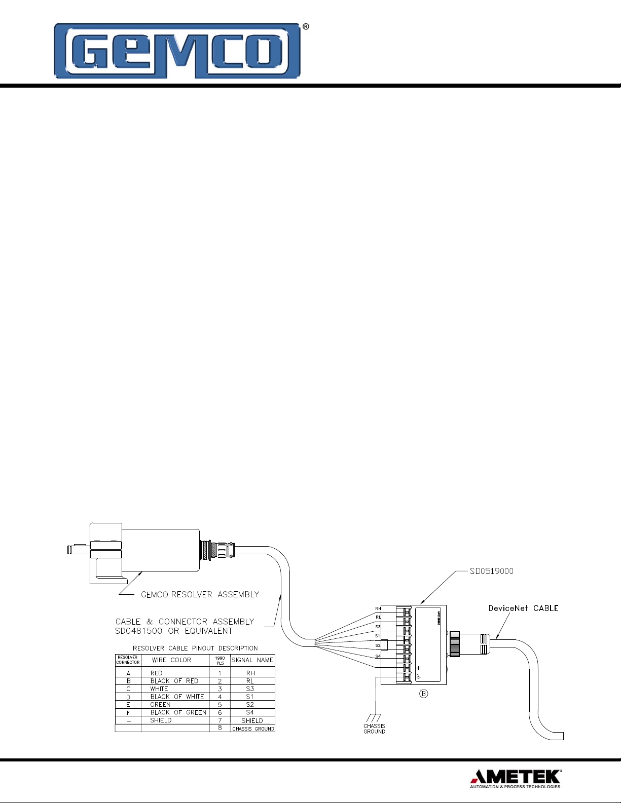
S2
Red
RH RL
B/R
B/W
White
Green
S1S3
GND
CHAS
Shield
S4
B/G
The DeviceNet Resolver combines the reliability
and resolution of continuous resolver position
sensing with the added flexibility of DeviceNet
communications. The resolver technology is the
same as other GEMCO resolvers which have been
proven in rugged applications like stamping press
automation. The rugged housing construction
is ideal for harsh industrial environments. All
embedded electronics are SMT constructed for the
ultimate reliability.
The DeviceNet Resolver plugs in, as a node on any
control system with a DeviceNet Scanner. Additional
resolvers are added by simply plugging into the
network. Continuous rotary positions data with
12-Bit resolution is provided. In addition, eight (8)
built-in user programmable setpoints are transmitted
over the network thus allowing direct control of
critical functions. All programming is done over the
DeviceNet network.
The DeviceNet Resolver provides flexibility and
cost savings when compared to other methods
of continuous position sensing. Each encoder is
easy to mount and wire using mini-change plug
connectors and avoiding cumbersome traditional
resolver cables. Since every DeviceNet network
is bus powered, there is no need for a separate
power supply. There are no port concentrators
to buy since all of the sensing and network
electronics are embedded within the resolver
housing. The DeviceNet Resolver and DeviceNet
scanner card are competitively priced with a plain
resolver and PLC resolver input card. Additional
DeviceNet Resolver units can be added on the
same DeviceNet network without adding additional
scanner cards. This approach is very useful when
more than one resolver per system is needed.
By using the DeviceNet Resolver it’s possible
to eliminate stand alone programmable limit
switches and other added electronic modules.
This means savings on equipment and installation
with the added benefits of improved reliability and
productivity.
1990DN Wiring Diagram
1080 N. Crooks Road • Clawson, MI 48017 • 800.635.0289 • 248.435.0700 • Fax 248.435.8120 • www.AMETEKAPT.com
3
Page 4

Chapter 2: DeviceNet Information
The DeviceNet Resolver operates as a “Group
2 only slave” device. It operates as an input only
device on the DeviceNet network. All device
configurations are accomplished by using any
DeviceNet software configuration tool.
The DeviceNet Resolver is capable of
communicating at all three DeviceNet baud rates,
125K, 250K, and 500K. The node address can
be set to any address, 0 - 63. There are several
parameters: scale factor, counting direction, and
8 programmable setpoint that are configured or
modified by the user through the Parameter Object.
(See section 4.0: DeviceNet Resolver Object
Model).
2.1: LED Operation
The DeviceNet Resolver is equipped with a Network
Status LED. The network Status LED operates as
follows:
Bit Strobe Message
A bit strobed message connection is a very fast
method by which a master sends one bit (Bit Strobe
Command) out on the network and receives up to
8 bytes of data (Bit Strobe Response) from each
slave device that supports a Bit Strobe Message
Connection. The DeviceNet Resolver disregards the
command message. No user-defined configuration
is required.
Polled I/O Message
A polled message connection is used for devices
that have inputs and outputs. It can also be used for
“Input Only” devices. The master sends out a Polled
Command to each individual device and the device
responds with an 8 byte Polled Response. The
Polled message connection is not the most efficient
message connection to use for “Input Only” devices
because there is a Command message sent to and
a Response message sent from each device. This
creates a lot of unnecessary network traffic.
Solid Green = Allocated by Master
Flashing Green = Passed Duplicate MAC ID Test
and is awaiting to be allocated by Master
Solid Red = Fatal error. Requires user intervention.
Check for duplicate MAC ID or baud rate
communication rate setting.
2.2: I/O Messaging
The DeviceNet Resolver supports Bit-Strobe
Message Connection as well as a Polled I/O
Message connection. The DeviceNet Resolver does
not support Cyclic I/O or Change-of-State Message
Connections.
Setpoint Data Position Data
0 1 2 3 4 5 6 7 8 9 10 11 12 13 14 15
Position Data RPM Data
16 17 18 19 20 21 22 23 24 25 26 27 28 29 30 31
RPM Data Not Used
32 33 34 35 36 37 38 39 40 41 42 43 44 45 46 47
Not Used
48 49 50 51 52 53 54 55 56 57 58 59 60 61 62 63
2.3: Data Format
The setpoint status is supplied in the first 8 bits
of the I/O message. One bit for each setpoint,
“0 = off” and “1 = on”. The next 16 bits will provide
the scaled resolver position information (4095
maximum). And finally, the next 16 bits will provide
the RPM data (1024 maximum). The entire I/O
message is 40 bits long. You will need to reserve 40
bits in your controller I/O image table.
4
1080 N. Crooks Road • Clawson, MI 48017 • 800.635.0289 • 248.435.0700 • Fax 248.435.8120 • www.AMETEKAPT.com
Page 5

Chapter 3: Getting Started
3.1: Establishing DeviceNet
Communications
NOTE: This manual assumes that the network is
configured in accordance with the DeviceNet wiring
specification.
1. Remove the DeviceNet Resolver from the box
and connect your DeviceNet cable to the 5-pin
mini connector on the back of the resolver
according to the DeviceNet wiring specifications.
2. Make sure that there is power on the DeviceNet
network when you connect the DeviceNet
Resolver to the network.
3. The DeviceNet Resolver will undergo an
initialization sequence, flashing the network
status LED. The LED will first turn green then red
and then flash green. At this point, the DeviceNet
Resolver has passed its duplicate MAC ID test
and is ready to be allocated by a master.
4. If the network status LED stays solid red, remove
the DeviceNet Resolver from the network and
then reconnect. If the LED is still solid red, then
go to section 3.2: Configure the Node Address
and Baud Rate.
3.2: Configure the Node
Address and Baud Rate
1. When the network status is flashing green you
may change the device node address (MAC ID)
and the baud rate using any DeviceNet software
configuration tool. Defaults are node address 63
and 125K baud.
2. If you change the node address, the DeviceNet
Resolver will undergo the initialization sequence
and assume the new node address.
3. If you change the baud rate, the new baud
rate will not take effect until power is cycled to
the DeviceNet Resolver and the initialization
sequence occurs.
4. Confirm the new node address and baud rate are
set correctly by using the software configuration
tool to scan the network for the DeviceNet
Resolver.
3.3: Parameter Configuration
After the baud rate and node address have been
established, the device parameters are ready to be
configured. The parameters must be configured in
the following sequence:
3.3.1: Scale Factor
The scale factor range is from 2 to 4096. The scale
factor can not exceed 4096. The scale factor is
configured through the Parameter Object. The
default scale factor is 4096.
NOTE: Changing the scale factor will result in
clearing the position offset and resetting all of the
setpoint values to zero. Therefore, the scale factor
should be set prior to configuring any setpoints or
position offset.
Set Parameter Instance 2 Attribute ID 1 Desired
Value. Desired Value = 2 to 4096.
3.3.2: Counting Direction
The DeviceNet Resolver can be configured to count
(increment) in either direction. The default direction
is clockwise.
Set Parameter Instance 3 Attribute ID 1 Desired
Value. Desired Value = 0 for clockwise, 1 for
counter clockwise.
1080 N. Crooks Road • Clawson, MI 48017 • 800.635.0289 • 248.435.0700 • Fax 248.435.8120 • www.AMETEKAPT.com
5
Page 6

3.3.3: Position Offset
The indicated position of the resolver can be
changed to synchronize or “zero” the resolver to the
machine it is attached to. The resolver position can
be changed by moving the resolver at the desired
position and writing the desired indicated position to
attribute 1 of the Position Object. All setpoints will be
based on this offset position. A valid position value
3.3.4: Setpoints
As indicated the DeviceNet Resolver has 8
programmable setpoints. Each setpoint is
individually programmed through the Parameter
Object. Each setpoint has an “On Position” value
and an “Off Position” value. All setpoint defaults are
set to 0. Each setpoint has only one “On” and
one “Off” per revolution.
can range between, and include, zero and the scale
factor. (i.e. 0 < position < scale factor).
NOTE: The setpoints can be changed after the
scale factor has been established. The setpoints
cannot be configured outside the scale factor range.
Setpoint 1 “On” Position Set Parameter Instance 5 Attribute ID 1 Desired On Position Value
Setpoint 1 “Off” Position Set Parameter Instance 6 Attribute ID 1 Desired Off Position Value
Setpoint 2 “On” Position Set Parameter Instance 7 Attribute ID 1 Desired On Position Value
Setpoint 2 “Off” Position Set Parameter Instance 8 Attribute ID 1 Desired Off Position Value
Setpoint 3 “On” Position Set Parameter Instance 9 Attribute ID 1 Desired On Position Value
Setpoint 3 “Off” Position Set Parameter Instance 10 Attribute ID 1 Desired Off Position Value
Setpoint 4 “On” Position Set Parameter Instance 11 Attribute ID 1 Desired On Position Value
Setpoint 4 “Off” Position Set Parameter Instance 12 Attribute ID 1 Desired Off Position Value
Setpoint 5 “On” Position Set Parameter Instance 13 Attribute ID 1 Desired On Position Value
Setpoint 5 “Off” Position Set Parameter Instance 14 Attribute ID 1 Desired Off Position Value
Setpoint 6 “On” Position Set Parameter Instance 15 Attribute ID 1 Desired On Position Value
Setpoint 6 “Off” Position Set Parameter Instance 16 Attribute ID 1 Desired Off Position Value
Setpoint 7 “On” Position Set Parameter Instance 17 Attribute ID 1 Desired On Position Value
Setpoint 7 “Off” Position Set Parameter Instance 18 Attribute ID 1 Desired Off Position Value
Setpoint 8 “On” Position Set Parameter Instance 19 Attribute ID 1 Desired On Position Value
Setpoint 8 “Off” Position Set Parameter Instance 20 Attribute ID 1 Desired Off Position Value
6
1080 N. Crooks Road • Clawson, MI 48017 • 800.635.0289 • 248.435.0700 • Fax 248.435.8120 • www.AMETEKAPT.com
Page 7

Chapter 4: DeviceNet Object Model
4.1: Object Model
4.1.1: Objects Present in the
DeviceNet Resolver
Optional/
Object
Identity (1) Required 1
Message Router (2) Required 1
DeviceNet (3) Required 1
Assembly (4) Required 1
Connection (5) Required 3
Parameter (15) Required 20
Position (100) Required 1
Setpoint (101) Required 8
RPM (102) Required 1
Required
Instances
# of
4.1.3: Object Interfaces
Object Interface
Identity (1) Message Router
Message Router (2) Explicit Message
DeviceNet (3) Message Router
Assembly #1 (4) I/O Connection or
Assembly #2 (4) Message Router
Connection (5) Message Router
Position (100) Message Router
Setpoint (101) Message Router
RPM (102) Message Router
Connection Instance
Message Router
4.1.2: Objects That Effect Behavior
Object Effect on Behavior
Identity (1) Supports the Reset Service
Message Router (2) No Effect
DeviceNet (3) Configures Port Attributes
Assembly #1 (4) I/O Assembly
Assembly #2 (4) Config Assembly
Connection (5) Establishes the number
of connections
Position (100) Configures the
position offset
Setpoint (101) Configures the
setpoint positions
RPM (102) No Effect
4.1.4: Identification of I/O Assembly
Instances
Instance
Number
1 Input Position Data/Setpoint Status/
2 Input Setpoint Data
Type Name
RPM Value
1080 N. Crooks Road • Clawson, MI 48017 • 800.635.0289 • 248.435.0700 • Fax 248.435.8120 • www.AMETEKAPT.com
7
Page 8

4.1.5: Format of I/O Assembly Data Attribute
Assembly #1 - I/O Assembly
Byte 7 6 5 4 3 2 1 0
0 Setpoint Status
1 Position Low
2 Position High
3 RPM Low
4 RPM High
Byte 7 6 5 4 3 2 1 0
0 Setpoint 1 On Position (Low Byte)
1 Setpoint 1 On Position (High Byte)
2 Setpoint 1 Off Position (Low Byte)
3 Setpoint 1 Off Position (High Byte)
4 Setpoint 2 On Position (Low Byte)
5 Setpoint 2 On Position (High Byte)
6 Setpoint 2 Off Position (Low Byte)
7 Setpoint 2 Off Position (High Byte)
8 Setpoint 3 On Position (Low Byte)
9 Setpoint 3 On Position (High Byte)
10 Setpoint 3 Off Position (Low Byte)
11 Setpoint 3 Off Position (High Byte)
12 Setpoint 4 On Position (Low Byte)
13 Setpoint 4 On Position (High Byte)
Assembly #2 - Config Assembly
14 Setpoint 4 Off Position (Low Byte)
15 Setpoint 4 Off Position (High Byte)
16 Setpoint 5 On Position (Low Byte)
17 Setpoint 5 On Position (High Byte)
18 Setpoint 5 Off Position (Low Byte)
19 Setpoint 5 Off Position (High Byte)
20 Setpoint 6 On Position (Low Byte)
21 Setpoint 6 On Position (High Byte)
22 Setpoint 6 Off Position (Low Byte)
23 Setpoint 6 Off Position (High Byte)
24 Setpoint 7 On Position (Low Byte)
25 Setpoint 7 On Position (High Byte)
26 Setpoint 7 Off Position (Low Byte)
27 Setpoint 7 Off Position (High Byte)
28 Setpoint 8 On Position (Low Byte)
29 Setpoint 8 On Position (High Byte)
30 Setpoint 8 Off Position (Low Byte)
31 Setpoint 8 Off Position (High Byte)
8
1080 N. Crooks Road • Clawson, MI 48017 • 800.635.0289 • 248.435.0700 • Fax 248.435.8120 • www.AMETEKAPT.com
Page 9

4.2: Standard Objects
4.2.1: Identity Object (Class ID = 1)
Attribute ID Access Rule Name Data Type Value
1 Get Vendor UNIT 0x009C
2 Get Product Type UINT 0x0000
3 Get Product Cod UINT 0x07C2
4 Get Revision STRUCT 01.00
5 Get Status WORD 0x0000
6 Get Serial # UDINT 0x00000001
7 Get Product Name STRUCT 15, “1986DN Resolver”
4.2.2: Message Router Object (Class ID = 2)
There is no externally visible interface to the Message Router Object.
4.2.3: DeviceNet Object (Class ID = 3)
There is a single instance of the DeviceNet Object for the DeviceNet Resolver. No class attributes are
supported.
Attribute ID Access Rule Name Data Type Value
1 Get/Set MACID USINT 0x63
2 Get/Set Baud Rate USINT 125K
3 Get/Set BOI BOOL 0x00 Hold in Reset
4 Get/Set Bus-off Counter USINT 0x00
5 Get Allocation Information STRUCT Allocate Service
4.2.4: Connection Object (Class ID = 5)
There are three instances of the connection object. Instance #1 is assigned to the explicit messaging
connection. Instance #2 is assigned to the Polled I/O connection. Instance #3 is assigned to the bit-strobe
I/O connection.
1080 N. Crooks Road • Clawson, MI 48017 • 800.635.0289 • 248.435.0700 • Fax 248.435.8120 • www.AMETEKAPT.com
9
Page 10

Explicit Message Connection Object (Instance #1)
Attribute ID Access Rule Name Data Type Value
1 Get State USINT 0x03
2 Get instance_type USINT 0x00
3 Get Xport Class trigger USINT 0x83
4 Get Produced connection ID UINT 0x5FB for MAC ID 63
5 Get Consumed connection ID UINT 0x5FC for MAC ID 63
6 Get initial comm characteristics USINT 0x21
7 Get produced connection size UINT 0x0025
8 Get consumed connection size UINT 0x0025
9 Get/Set expected packet rate UINT Application Dependent
10 N/A N/A N/A Not Used
11 N/A N/A N/A Not Used
12 Get Watchdog timeout action USINT 0x01
13 Get Produced path length UINT 0x0000
14 Get Produced path Array of USINT 0x20 0x04 0x24 0x01 0x30 0x03
15 Get consumed path length UINT 0x0000
16 Get consumed path Array of USINT <NULL>
Poll I/O Message Connection Object (Instance #2)
Attribute ID Access Rule Name Data Type Value
1 Get State USINT 0x03
2 Get instance_type USINT 0x01
3 Get Xport Class trigger USINT 0x82
4 Get Produced connection ID UINT 0x3FF for MAC ID 63
5 Get consumed connection ID UINT 0x5FD for MAC ID 63
6 Get initial comm characteristics USINT 0x01
7 Get produced connection size UINT 0x0005
8 Get consumed connection size UINT 0x0000
9 Get/Set expected packet rate UINT Application Dependent
10 N/A N/A N/A Not Used
11 N/A N/A N/A Not Used
12 Get Watchdog timeout action USINT 0x00
13 Get Produced path length UINT 0x0006
10
14 Get Produced path Array of USINT 0x20 0x04 0x24 0x01 0x30 0x03
15 Get consumed path length UINT 0x0000
16 Get consumed path Array of USINT <NULL>
1080 N. Crooks Road • Clawson, MI 48017 • 800.635.0289 • 248.435.0700 • Fax 248.435.8120 • www.AMETEKAPT.com
Page 11

Bit Strobe I/O Message Connection Object (Instance #3)
Attribute ID Access Rule Name Data Type Value
1 Get State USINT 0x03
2 Get instance_type USINT 0x01
3 Get Xport Class trigger USINT 0x82
4 Get Produced connection ID UINT 0x3BF for MAC ID 63
5 Get consumed connection ID UINT 0x408 for MAC ID 1
6 Get initial comm characteristics USINT 0x02
7 Get produced connection size UINT 0x0005
8 Get consumed connection size UINT 0x0008
9 Get/Set expected packet rate UINT Application Dependent
10 N/A N/A N/A Not Used
11 N/A N/A N/A Not Used
12 Get Watchdog timeout action USINT 0x00
13 Get Produced path length UINT 0x0006
14 Get Produced path Array of USINT 0x20 0x04 0x24 0x01 0x30 0x03
15 Get consumed path length UINT 0x0000
16 Get consumed path Array of USINT <NULL>
4.2.5: Parameter Object (Class ID = 15)
The parameter object supports the class attributes and 20 instances.
Class Attributes
Attribute ID Access Rule Name Data Type Value
2 Get Max Instance UINT 0x0014
8 Get Parameter Class Descriptor WORD 0x0009
9 Get Configuration Assembly Instance UINT 0x0002
1080 N. Crooks Road • Clawson, MI 48017 • 800.635.0289 • 248.435.0700 • Fax 248.435.8120 • www.AMETEKAPT.com
11
Page 12

Parameter Instance #1 (Position)
Attribute ID Access Rule Name Data Type Value
1 Get Parameter Value UINT Current Position
2 Get Link Path Size USINT 0x06
3 Get Link Path ARRAY “0x20 0x64 0x24 0x01 0x30 0x01”
4 Get Descriptor WORD 0x0030
5 Get Data Type USINT 0x02
6 Get Data Size USINT 0x02
Parameter Instance #2 (Scale Factor)
Attribute ID Access Rule Name Data Type Value
1 Get/Set Parameter Value UINT Current Scale Factor
2 Get Link Path Size USINT 0x06
3 Get Link Path ARRAY “0x20 0x64 0x24 0x01 0x30 0x02”
4 Get Descriptor WORD 0x0000
5 Get Data Type USINT 0x02
6 Get Data Size USINT 0x02
Parameter Instance #3 (Direction)
Attribute ID Access Rule Name Data Type Value
1 Get/Set Parameter Value USINT Current Direction
2 Get Link Path Size USINT 0x06
3 Get Link Path ARRAY “0x20 0x64 0x24 0x01 0x30 0x03”
4 Get Descriptor WORD 0x0002
5 Get Data Type USINT 0x08
6 Get Data Size USINT 0x01
Parameter Instance #4 (RPM)
Attribute ID Access Rule Name Data Type Value
1 Get Parameter Value USINT Current RPM Value
2 Get Link Path Size USINT 0x06
3 Get Link Path ARRAY “0x20 0x66 0x24 0x01 0x30 0x01”
4 Get Descriptor WORD 0x0030
5 Get Data Type USINT 0x02
6 Get Data Size USINT 0x02
12
1080 N. Crooks Road • Clawson, MI 48017 • 800.635.0289 • 248.435.0700 • Fax 248.435.8120 • www.AMETEKAPT.com
Page 13

Parameter Instance #5 (Setpoint 1 on position)
Attribute ID Access Rule Name Data Type Value
1 Get/Set Parameter Value USINT Setpoint 1 on position
2 Get Link Path Size USINT 0x06
3 Get Link Path ARRAY “0x20 0x65 0x24 0x01 0x30 0x02”
4 Get Descriptor WORD 0x0000
5 Get Data Type USINT 0x02
6 Get Data Size USINT 0x02
Parameter Instance #6 (Setpoint 1 off position)
Attribute ID Access Rule Name Data Type Value
1 Get/Set Parameter Value USINT Setpoint 1 off position
2 Get Link Path Size USINT 0x06
3 Get Link Path ARRAY “0x20 0x65 0x24 0x01 0x30 0x03”
4 Get Descriptor WORD 0x0000
5 Get Data Type USINT 0x02
6 Get Data Size USINT 0x02
Parameter Instance #7 (Setpoint 2 on position)
Attribute ID Access Rule Name Data Type Value
1 Get/Set Parameter Value USINT Setpoint 2 on position
2 Get Link Path Size USINT 0x06
3 Get Link Path ARRAY “0x20 0x65 0x24 0x02 0x30 0x02”
4 Get Descriptor WORD 0x0000
5 Get Data Type USINT 0x02
6 Get Data Size USINT 0x02
Parameter Instance #8 (Setpoint 2 off position)
Attribute ID Access Rule Name Data Type Value
1 Get/Set Parameter Value USINT Setpoint 2 off position
2 Get Link Path Size USINT 0x06
3 Get Link Path ARRAY “0x20 0x65 0x24 0x02 0x30 0x03”
4 Get Descriptor WORD 0x0000
5 Get Data Type USINT 0x02
6 Get Data Size USINT 0x02
1080 N. Crooks Road • Clawson, MI 48017 • 800.635.0289 • 248.435.0700 • Fax 248.435.8120 • www.AMETEKAPT.com
13
Page 14

Parameter Instance #9 (Setpoint 3 on position)
Attribute ID Access Rule Name Data Type Value
1 Get/Set Parameter Value USINT Setpoint 3 on position
2 Get Link Path Size USINT 0x06
3 Get Link Path ARRAY “0x20 0x65 0x24 0x03 0x30 0x02”
4 Get Descriptor WORD 0x0000
5 Get Data Type USINT 0x02
6 Get Data Size USINT 0x02
Parameter Instance #10 (Setpoint 3 off position)
Attribute ID Access Rule Name Data Type Value
1 Get/Set Parameter Value USINT Setpoint 3 off position
2 Get Link Path Size USINT 0x06
3 Get Link Path ARRAY “0x20 0x65 0x24 0x03 0x30 0x03”
4 Get Descriptor WORD 0x0000
5 Get Data Type USINT 0x02
6 Get Data Size USINT 0x02
Parameter Instance #11 (Setpoint 4 on position)
Attribute ID Access Rule Name Data Type Value
1 Get/Set Parameter Value USINT Setpoint 4 on position
2 Get Link Path Size USINT 0x06
3 Get Link Path ARRAY “0x20 0x65 0x24 0x04 0x30 0x02”
4 Get Descriptor WORD 0x0000
5 Get Data Type USINT 0x02
6 Get Data Size USINT 0x02
Parameter Instance #12 (Setpoint 4 off position)
Attribute ID Access Rule Name Data Type Value
1 Get/Set Parameter Value USINT Setpoint 4 off position
2 Get Link Path Size USINT 0x06
3 Get Link Path ARRAY “0x20 0x65 0x24 0x04 0x30 0x03”
4 Get Descriptor WORD 0x0000
5 Get Data Type USINT 0x02
6 Get Data Size USINT 0x02
14
1080 N. Crooks Road • Clawson, MI 48017 • 800.635.0289 • 248.435.0700 • Fax 248.435.8120 • www.AMETEKAPT.com
Page 15

Parameter Instance #13 (Setpoint 5 on position)
Attribute ID Access Rule Name Data Type Value
1 Get/Set Parameter Value USINT Setpoint 5 on position
2 Get Link Path Size USINT 0x06
3 Get Link Path ARRAY “0x20 0x65 0x24 0x05 0x30 0x02”
4 Get Descriptor WORD 0x0000
5 Get Data Type USINT 0x02
6 Get Data Size USINT 0x02
Parameter Instance #14 (Setpoint 5 off position)
Attribute ID Access Rule Name Data Type Value
1 Get/Set Parameter Value USINT Setpoint 5 off position
2 Get Link Path Size USINT 0x06
3 Get Link Path ARRAY “0x20 0x65 0x24 0x05 0x30 0x03”
4 Get Descriptor WORD 0x0000
5 Get Data Type USINT 0x02
6 Get Data Size USINT 0x02
Parameter Instance #15 (Setpoint 6 on position)
Attribute ID Access Rule Name Data Type Value
1 Get/Set Parameter Value USINT Setpoint 6 on position
2 Get Link Path Size USINT 0x06
3 Get Link Path ARRAY “0x20 0x65 0x24 0x06 0x30 0x02”
4 Get Descriptor WORD 0x0000
5 Get Data Type USINT 0x02
6 Get Data Size USINT 0x02
Parameter Instance #16 (Setpoint 6 off position)
Attribute ID Access Rule Name Data Type Value
1 Get/Set Parameter Value USINT Setpoint 6 off position
2 Get Link Path Size USINT 0x06
3 Get Link Path ARRAY “0x20 0x65 0x24 0x06 0x30 0x03”
4 Get Descriptor WORD 0x0000
5 Get Data Type USINT 0x02
6 Get Data Size USINT 0x02
1080 N. Crooks Road • Clawson, MI 48017 • 800.635.0289 • 248.435.0700 • Fax 248.435.8120 • www.AMETEKAPT.com
15
Page 16

Parameter Instance #17 (Setpoint 7 on position)
Attribute ID Access Rule Name Data Type Value
1 Get/Set Parameter Value USINT Setpoint 7 on position
2 Get Link Path Size USINT 0x06
3 Get Link Path ARRAY “0x20 0x65 0x24 0x07 0x30 0x02”
4 Get Descriptor WORD 0x0000
5 Get Data Type USINT 0x02
6 Get Data Size USINT 0x02
Parameter Instance #18 (Setpoint 7 off position)
Attribute ID Access Rule Name Data Type Value
1 Get/Set Parameter Value USINT Setpoint 7 off position
2 Get Link Path Size USINT 0x06
3 Get Link Path ARRAY “0x20 0x65 0x24 0x07 0x30 0x03”
4 Get Descriptor WORD 0x0000
5 Get Data Type USINT 0x02
6 Get Data Size USINT 0x02
Parameter Instance #19 (Setpoint 8 on position)
Attribute ID Access Rule Name Data Type Value
1 Get/Set Parameter Value USINT Setpoint 8 on position
2 Get Link Path Size USINT 0x06
3 Get Link Path ARRAY “0x20 0x65 0x24 0x08 0x30 0x02”
4 Get Descriptor WORD 0x0000
5 Get Data Type USINT 0x02
6 Get Data Size USINT 0x02
Parameter Instance #20 (Setpoint 8 off position)
Attribute ID Access Rule Name Data Type Value
1 Get/Set Parameter Value USINT Setpoint 8 off position
2 Get Link Path Size USINT 0x06
3 Get Link Path ARRAY “0x20 0x65 0x24 0x08 0x30 0x03”
4 Get Descriptor WORD 0x0000
5 Get Data Type USINT 0x02
6 Get Data Size USINT 0x02
16
1080 N. Crooks Road • Clawson, MI 48017 • 800.635.0289 • 248.435.0700 • Fax 248.435.8120 • www.AMETEKAPT.com
Page 17

4.3: Application Specific Objects
4.3.1: Position Object (Class ID = 100)
There is a single instance of the position object for the DeviceNet Resolver. No class attributes are
supported. All the instances are gettable and settable. The table below shows the values:
Attribute ID Access Rule Name Data Type Value
1 Get/Set Magnet Position UINT Current Position
2 Get/Set Scale Factor UINT Current Scale Factor
3 Get/Set Direction USING Current Direction
Valid position values range from 0 to the current scale factor. Valid scale factor values range from 2 to
4096. Direction value 0 indicates that the counts will increase clockwise. Direction value 1 indicates that the
counts will increase counter-clockwise.
4.3.2: Setpoint Object (Class ID = 101)
There are eight instances of the setpoint object in the DeviceNet Resolver. No class attributes are
supported. All setpoint position data is gettable and settable. The setpoint status is gettable.
Attribute ID Access Rule Name Data Type Value
1 Get Setpoint Status BOOL 0x00
2 Get/Set Setpoint On Position UINT 0x0000
3 Get/Set Setpoint Off Position UINT 0x0000
Valid setpoint values range between, and include, zero and the scale factor.
(i.e. < setpoint < scale factor)
4.3.3: RPM Object (Class ID = 102)
There is a single instance of the RPM object for the DeviceNet Resolver. No class attributes are supported.
All the instances are gettable but not settable. The table below shows the values:
Attribute ID Access Rule Name Data Type Value
1 Get RPM UINT Current RPM Value
1080 N. Crooks Road • Clawson, MI 48017 • 800.635.0289 • 248.435.0700 • Fax 248.435.8120 • www.AMETEKAPT.com
17
Page 18

4.4: Configuration Notes
Network Baud Rate
DeviceNet Resolver
Node Address
Scale Factor
Counting Direction
Setpoint 1 “On”
Setpoint 1 “Off”
Setpoint 2 “On”
Setpoint 2 “Off”
Setpoint 3 “On”
Setpoint 3 “Off”
Setpoint 4 “On”
Setpoint 4 “Off”
Setpoint 5 “On”
Setpoint 5 “Off”
Setpoint 6 “On”
Setpoint 6 “Off”
Setpoint 7 “On”
Setpoint 7 “Off”
Setpoint 8 “On”
Setpoint 8 “Off”
18
1080 N. Crooks Road • Clawson, MI 48017 • 800.635.0289 • 248.435.0700 • Fax 248.435.8120 • www.AMETEKAPT.com
Page 19

Appendix
Specifications
Resolver
Resolution 12 bit resolution (4096 counts)
RPM 1024 max.
DeviceNet
Conformance This product has been tested by
Power Requirements
Inrush
Device Type “Generic”
Communications Group 2 slave only
Messages supported Polled, Bit Strobed, Explicit
Baud Rates 125K, 250K, 500K
Data
Update Rate
Position Rate
RPM
Scale Factor 2 to 4096
Position Range 0 to 1 less than scale factor
Setpoints Separate ON and OFF points for each
Quantity 8
Range 0 to 1 less than scale factor
Approvals CE
Environmental
Temperature
Operating
Storage
ODVA’s authorized Independent Test
Lab and found to comply with ODVA
Conformance Test Software Version
A-12.
92mA @ 11Vdc typical
67mA @ 24Vdc typical
350mA @ 11Vdc for 20 ms
450mA @ 25Vdc for 10 ms
915µs
29.29 ms
setpoint
-20°C to +70°C
-40°C to +85°C
EMC Specifications
Specifications and Related Documents
The DeviceNet Resolver was tested to and complied with
the limits of the following specifications:
EN50081-1:1992
EN55011/A:1999
EN50082-2:1995
EN61000-4-2:1995
EN61000-4-3:1998
+ Amendment 1
EN61000-4-4:1995
ENV50144:1993
EN61010-1:1993 Safety Requirements for Electrical
EMC, Generic emission standard,
Light Industrial Limits and methods of
measurement of radio characteristics
of industrial, scientific and medical
(ISM) Radio Frequency equipment,
Class B, Group 1.
Generic immunity standard, Industrial
ESD Immunity,
Performance Criteria B.
Radiated RF Immunity,
Performance Criteria A.
Electrical Fast Transient Immunity,
Performance Criteria B.
Conducted RF Immunity,
Performance Criteria A.
Equipment for Measurement, Control
and Laboratory Use.
NOTE: To meet EMC requirements, add Ferrite (Fair-Rite
Corporation P/N: 0444167281) to resolver cable located
adjacent to DeviceNet connector.
1080 N. Crooks Road • Clawson, MI 48017 • 800.635.0289 • 248.435.0700 • Fax 248.435.8120 • www.AMETEKAPT.com
19
Page 20

Other Products
Copyright 2007 by AMETEK Automation & Process Technologies.
All Rights Reserved. Made in the USA.
1080 N. Crooks Road, Clawson, MI 48017-1097
Phone 248-435-0700 Toll Free 800-635-0289
Fax 248-435-8120 www.ametekapt.com
DNRES.M3R
3/07.Z35
 Loading...