

Page 1
1980 Rotating Cam Limit Switches
Ordering Guide & Technical Information
Page 2
Features
• Precision Cam adjustment at any angular
position of the Camshaft
• Speeds from 0 to 500 RPM in either direction
• No special Cams required for any contact
setting from 4° to 356°
• No tools required to adjust Cam setting
• Accurate repeatability
• GEMCO rugged duty precision snap action
switches
• U.L. recognized switches under fi le E56660
Accessories
The following accessories can be obtained with
the GEMCO Rotating Cam Limit Switch:
For OSHA Standards
• Motion Detector *
• GEMCO DRIVE-CHEK
Either of the above is necessary for mechanical
press application
• Dual Shaft Cam Switch
Consult manufacturer for desired accessories
®
*
Applications
GEMCO’s all new Micro-Adjust Rotating Cam
Limit Switch is a pilot device used for heavy
duty material handling mechanisms, mechanical
presses,* packaging machines, rotary table, and in
many other applications where accurate, repetitive,
and sequential operations are required in control
circuitry.
• Straight Drive and Right Angle Gear
Reducers
• Timing Dial and Timing Dial Window
• Electrical Wiring per Customer’s Specifi cation
• Motor Driven Rotating Cam Limit Switch with
AC or DC for Adjustable Speed Drives
• Potentiometer driven off the Camshaft
• Spring Return Mechanism
• Plug-In Socket
• Double Ended Shafts
• Pilot Lights
• 3 Way and 4 Way Air Valves directly
interchangeable with switches
• Special Conduit Opening
• Special shaft extensions and keyway
• Adjustable Coupling (See Catalog Section
3001)
• Special Cams & Large 6” Cams for Higher
Resolution
• Combination Adjustable-ln-Motion and MicroAdjust Circuits (see Catalog Section 1981)
• Electric Clutch and/or Brake
• Separate Terminal Strips
• Add-A-Cam Feature
• Factory Adjustment of Cams Available
• Open Type Units
• Dual Shafts
When motion is expressed in shaft rotation, either
through a roller chain, gear train, or directly, the
GEMCO Rotating Cam Limit Switch makes it
possible to open or close independent circuits at
any desired angular position.
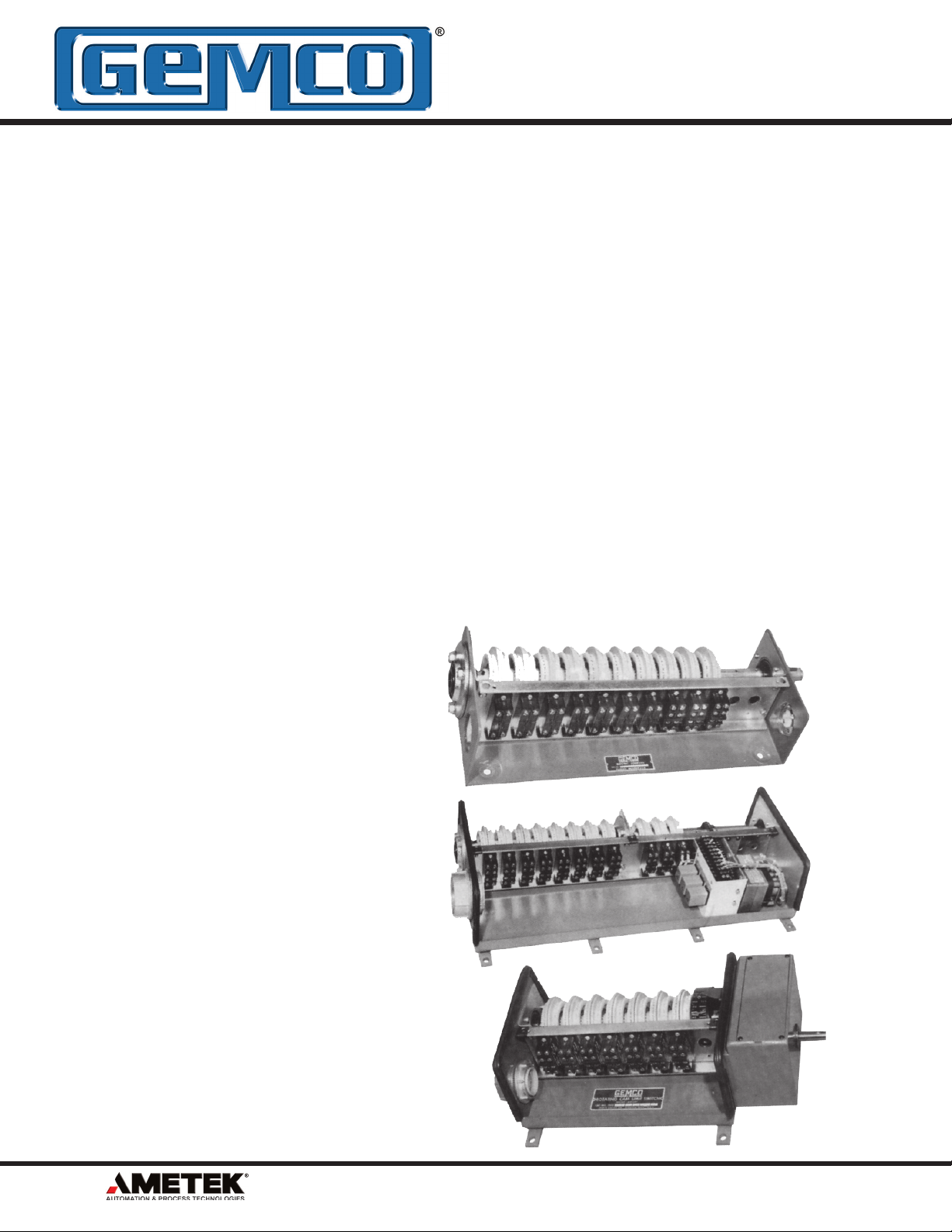
FIG. 1
FIG. 2
FIG. 3
2
1080 N. Crooks Road • Clawson, MI 48017-1097 USA • 800.635.0289 • 248.435.0700 • Fax: 248.435.8120 • www.AMETEKAPT.com
Page 3
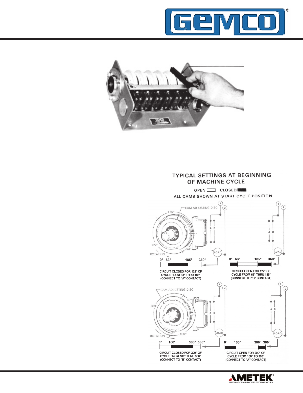
Easy Set-Up
Procedure
READ CAM
SETTING HERE
ALWAYS VIEW
CAMSHAFT ROTATION
FROM RIGHT SIDE
One Turn of Adjusting Dial
Moves Cam 10°
(Adjusting Tool #P0034600
Inside Cover of Each Unit)
Mounting of Unit
FRONT SIDE
Mount the assembly and couple input shaft to the
driving member with the shaft keyway up and in line
with the positioning arrow on the bearing end plate.
The machine should be in the start cycle position.
Establishing Camshaft
Direction of Rotation
Cam settings should be made with the
Camshaft uppermost to the viewer. The picture
at the top right illustrates this viewing position
and also shows the adjusting tool being applied
to the adjusting wheel. Shaft rotation is always
established off the right end of the unit even
when the input shaft, whether direct or through
a gear reducer, is situated at the left end.
As an
aid to designating shaft rotation when a gear
reducer is used, consult page 14 of this catalog
section.
Cam Settings
SWITCH SIDE
For clockwise rotation, set ‘’make’’ angle with
the black dial and ‘’break’’ with the red dial for
dwell settings less than 180°. Reverse colors for
dwells 180° or greater.
For counterclockwise rotation, set ‘’make’’ angle
with the white dial and ‘’break’’ with the yellow
dial. Reverse colors for dwells 180° or greater.
Switch connections should be made in
accordance with the illustrations to the right,
which incidentally are both clockwise rotating
examples.
1080 N. Crooks Road • Clawson, MI 48017-1097 USA • 800.635.0289 • 248.435.0700 • Fax: 248.435.8120 • www.AMETEKAPT.com
3
Page 4
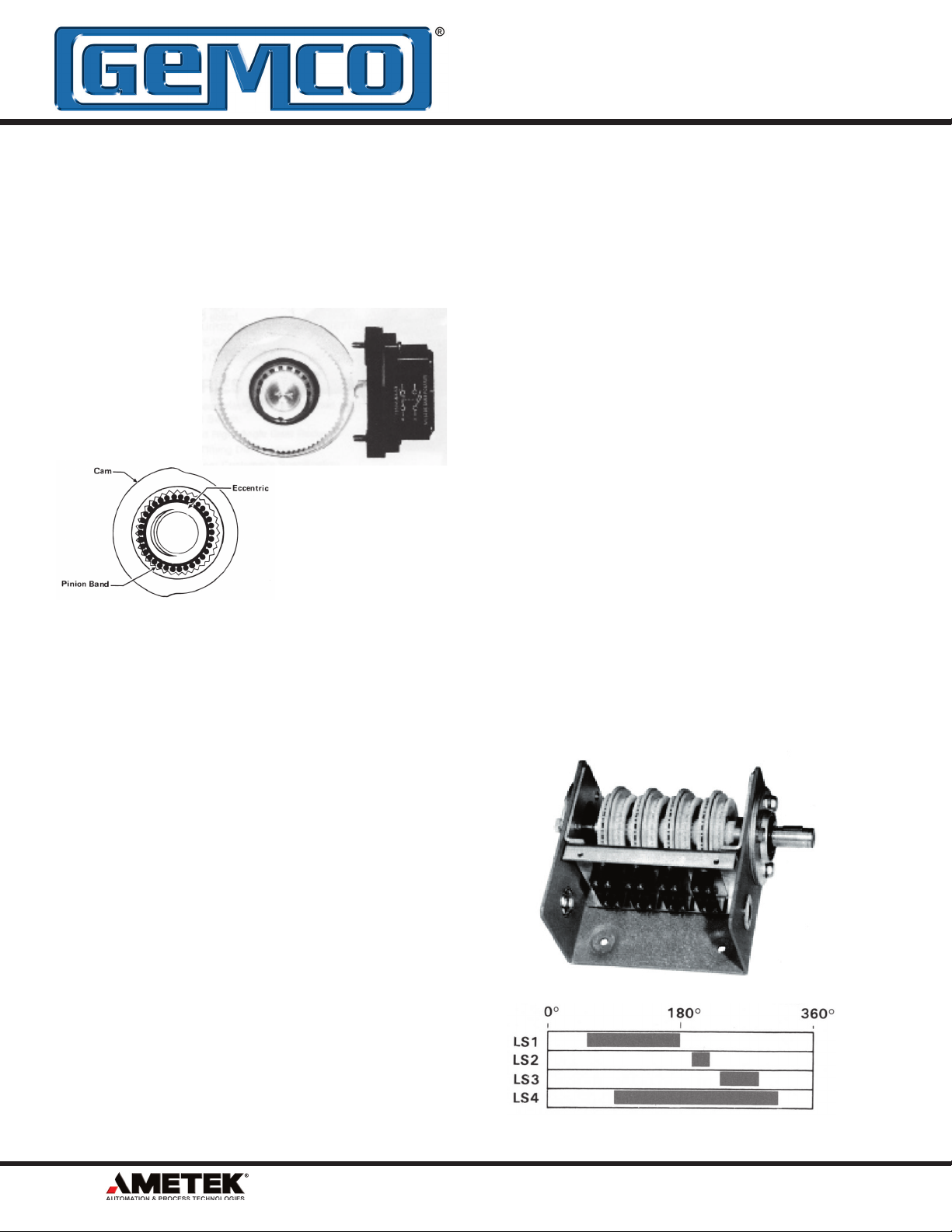
Description
Technical Data
Precision, rugged duty snap action switches,
extremely accurate cam adjustments with a heavy
duty shaft, rugged case and lifetime sealed ball
bearings, have been combined by GEMCO to
provide the most versatile and dependable Rotating
Cam Limit Switch available.
No Special Cams are Required
The accurate cam adjustments are made possible
by the use of a separate reduction drive in each half
of a circuit cam block assembly. This drive provides
a 36 to 1 ratio which means that one revolution of
the adjustment wheel will advance or retard the cam
setting by 10 degrees.
• The maximum temperature with full electrical load
is 185°F. The minimum operating temperature is 50°F minimum cam adjusting temperature is -10°F.
• Standard GEMCO Rotating Cam Limit Switches
have a rating of 50 pounds end thrust and 500
pounds radial load on standard shaft extensions.
• Torque Required - .6 lb. - In/Circuit.
• Repeatability +/- 1/4°
Snap Action Switches
All standard GEMCO Rotating Cam Limit Switches
employ SPDT precision type snap action switches
which provide the advantage of double-break
contacts and are actuated at a uniform rate to give
long life. DPDT switches can be provided upon
request. Any number of circuits from 1 to 40 may be
supplied as standard in Nema 1, Nema 4, Nema 7
and Nema 12 enclosures.
Each switch setting can be adjusted to your circuit
requirements.
arrangements is available with the GEMCO Rotating
Cam Limit Switch, with no special mounting cams,
dogs, etc. for contact settings.
GEMCO Microadjust Cams Provide
Unlimited Circuit Versa
An unlimited selection of circuit
tility
For most applications, therefore, no special cams
are necessary and settings may be changed at any
angular position of the camshaft.
• Lifetime Sealed Ball Bearing allows mounting in
any position.
• Large Cover Openings for ease of wiring.
No Minimum Speed is specified because snap
•
action contacts are used. Maximum rated speed
of the Camshaft is 500 RPM and can be rotated
either clockwise or counterclockwise.
Two types of compact integrally Mounted Gear
•
Reducers are available with ratios of 1:1 through
600:1. They can also be supplied with speed
multipliers up to 1:8.
4
1080 N. Crooks Road • Clawson, MI 48017-1097 USA • 800.635.0289 • 248.435.0700 • Fax: 248.435.8120 • www.AMETEKAPT.com
Page 5
Electrical Switches
Description
The GEMCO Precision Snap Switches are designed
for industrial duty applications where compact
size, complete reliability and millions of trouble free
operations are required.
The housing is molded material which has excellent
resistance to arcing and carbon tracking. The
operating button is of molded nylon, a material with
excellent wear characteristics.
The button is well guided at the top and bottom to
insure accurate repeatability and minimum wear.
The switches are individually mounted and can be
readily replaced without the need of adjustment or
alignment. All switches have binder head terminal
screws which are accessible for wiring with either
stripped or wire lug connections.
Any combination of single-pole double-throw or
double-pole double-throw snap action switches can
be supplied with the GEMCO Rotating Cam Limit
Switch.
Electrical Contact Ratings
AC
Inductive Pilot Duty 35% Power Factor Resistive 75% Power Factor Inductive Pilot Duty and Resistive
Make Break
Switch
Type Contacts Volts
1950-4 DPDT 115
230
440
575
1950-1 SPDT 110
220
440
600
30
15
7.5
6
40
20
10
8
VA Amps
3450
3450
3450
3450
0.75
--
--
--
--
3
1.5
0.6
15
10
6
5
VA
345
345
345
345
--
--
--
--
Continuous
rying Amps
10
10
10
10
15
15
15
15
NOTE:
Refer to Catalog Section 1950 for detailed
information pertaining to all Standard and Special
Switch Options.
DC
Amps
Double-
Throw
0.2
0.1
--
--
0.25
0.1
--
--
Continuous
Carrying AmpsAmps
Car-
Make, Break and Continuous
Carrying Amperes
10
10
10
10
15
15
15
15
Volts
115
230
600
-115
230
600
--
Make and Break
Single-
Throw
1.0
0.3
0.1
--
0.5
0.25
0.05
--
10
10
10
-15
15
15
--
1080 N. Crooks Road • Clawson, MI 48017-1097 USA • 800.635.0289 • 248.435.0700 • Fax: 248.435.8120 • www.AMETEKAPT.com
5
Page 6
1980 1 04 – R – SP — X
NUMBER
OF CAMS
ENCLOSURE
TYPE
1980 Standard
1980R Built-In Resolver
SEE PAGE 10
FOR CATALOG
NUMBER
X NO TIMING DIAL
HORIZ.
Mtg.
VERT.
Mtg.
SWITCH OPTION
— NO SWITCH OPTION
R RUBBER BOOT
TD1 C.W. ROTATION
{
TD2 C.C.W. ROT
TD3 C.W. ROT
{
TD4 C.W. ROT
* NOTE: If window is required for
timing dial, replace D with W in
Catalog Number (i.e., TW1)
HORIZONTAL Mtg.
NOTE: Timing dial always mounted
at right hand and as shown, takes one
circuit space, as viewed from right side.
TIMING DIAL*
ATION
ATION
ATION
}
c.w.
RIGHT
Side
TIMING DIAL
DECAL
TD1 NP-76-B
TD2 NP-71-B
TD3 NP-78-B
TD4 NP-77-B
c.w.
RIGHT
VERTICAL Mtg.
Side
SWITCH TYPE
SINGLE POLE
SP
DOUBLE
DOUBLE POLE
DP
DOUBLE
SPDT
**SPP
PLUG-IN SOCKET
DPDT
**DPP
PLUG-IN SOCKET
SPDT
SPK
CLAMP
SHAFT EXTENSION
R RIGHT HAND
L LEFT HAND
D DOUBLE ENDED
NO SHAFT EXTENSION
X
OPPOSITE GEAR BOX
EXTENSION OPPOSITE
SHAFT
Y
GEAR BOX
THROW
THROW
WITH
WITH
WITH
TERMINAL
** When plug-in switches are specified, one extra circuit space must be allowed for in the enclosure.
6
1080 N. Crooks Road • Clawson, MI 48017-1097 USA • 800.635.0289 • 248.435.0700 • Fax: 248.435.8120 • www.AMETEKAPT.com
Page 7

R
TYPE OF GEAR REDUCER
R RIGHT ANGLE
S STRAIGHT DRIVE
M MULTIPLIER DRIVE
** For straight drive gear reducers with 1970
Drive Chek, refer to section 1970 for shaft
extension location.
1.5
GEAR REDUCER
RATIO
1.2 1.2:1
1.25 1.25:1 1.25:1
1.33 1.33:1 1.33:1
4.75 4.75:1
12.5 12.5:1
Straight
1 1.1
1.5 1.5:1 1.5:1
1.6 1.6:1 1.6:1
2.2 2.2:1
2.5 2.5:1 2.5:1
7.5 7.5:1 7.5:1
8.5 8.5:1 8.5:1
10 10:1 10:1
12 12:1 12:1
14 14:1 14:1
15 15:1 15:1
16 16:1 16:1
17 17:1
18 18:1 18:1
20 20:1 20:1
24 24:1 24:1
25 25:1 25:1
28 28:1 28:1
30 30:1 30:1
32 32:1 32:1
35 35:1
36 36:1 36:1
40 40:1 40:1
48 48:1 48:1
50 50:1 50:1
60 60:1 60:1
64 64:1 64:1
72 72:1
80 80:1 80:1
96 96:1 96:1
100 100:1 100:1
200 200:1
400 400:1
500 500:1
600 600:1
*6
*7 1:7
*8 1:8
Drive
2 2:1 2:1
3 3:1 3:1
4 4:1 4:1
5 5:1 5:1
6 6:1 6:1
7 7:1 7:1
8 8:1 8:1
GEAR MUL
2 1:2
3 1:3
4 1:4
5 1:5
TIPLIER
1:6
Right
Angle
R1
R1
R2
R3
R4
R5
R6
R7
R8
L1
L2
L3
L4
L5
L6
L7
L8
R**
L**
NOTE: Gear reducer must be ordered in the required
position. It cannot be changed in the field.
SHAFT LOCATION
Right Angle Gear Reducer
Check Shaft Location for Possible Interference
Straight Drive Gear Reducer
* Number of Circuits Restricted — Consult Factory
1080 N. Crooks Road • Clawson, MI 48017-1097 USA • 800.635.0289 • 248.435.0700 • Fax: 248.435.8120 • www.AMETEKAPT.com
7
Page 8

NEMA 1 NEMA 4 & 5 NEMA 7 NEMA 12
Number
of
Circuits
1
2
3
4
5
6
7
8
9
10
11
12
13
14
15
16
17
18
19
20
21
22
23
24
25
26
27
28
29
30
31
32
33
34
35
36
37
38
39
40
NEMA 1 NEMA 4 & 5 NEMA 7 NEMA 12
Catalog
Number
1980-101
1980-102
1980-103
*1980-104
1980-105
*1980-106
1980-107
*1980-108
1980-109
1980-110
1980-111
*1980-112
1980-113
1980-114
1980-115
1980-116
1980-117
1980-118
1980-119
1980-120
1980-121
1980-122
1980-123
1980-124
1980-125
1980-126
1980-127
1980-128
1980-129
1980-130
1980-131
1980-132
1980-133
1980-134
1980-135
1980-136
1980-137
1980-138
1980-139
1980-140
Cat. No. w/
Resolver
1980R-101
1980R-102
1980R-103
1980R-104
1980R-105
1980R-106
1980R-107
1980R-108
1980R-109
1980R-110
1980R-111
1980R-112
1980R-113
1980R-114
1980R-115
1980R-116
1980R-117
1980R-118
1980R-119
1980R-120
1980R-121
1980R-122
1980R-123
1980R-124
1980R-125
1980R-126
1980R-127
1980R-128
1980R-129
1980R-130
1980R-131
1980R-132
1980R-133
1980R-134
1980R-135
1980R-136
Catalog
Number
1980-401
1980-402
1980-403
1980-404
1980-405
1980-406
1980-407
1980-408
1980-409
1980-410
1980-411
1980-412
1980-413
1980-414
1980-415
1980-416
1980-417
1980-418
1980-419
1980-420
1980-421
1980-422
1980-423
1980-424
1980-425
1980-426
1980-427
1980-428
1980-429
1980-430
1980-431
1980-432
1980-433
1980-434
1980-435
1980-436
1980-437
1980-438
1980-439
1980-440
Cat. No. w/
Resolver
1980R-401
1980R-402
1980R-403
1980R-404
1980R-405
1980R-406
1980R-407
1980R-408
1980R-409
1980R-410
1980R-411
1980R-412
1980R-413
1980R-414
1980R-415
1980R-416
1980R-417
1980R-418
1980R-419
1980R-420
1980R-421
1980R-422
1980R-423
1980R-424
1980R-425
1980R-426
1980R-427
1980R-428
1980R-429
1980R-430
1980R-431
1980R-432
1980R-433
1980R-434
1980R-435
1980R-436
Catalog
Number
1980-701
1980-702
1980-703
1980-704
1980-705
1980-706
1980-707
1980-708
1980-709
1980-710
1980-711
1980-712
1980-713
1980-714
1980-715
1980-716
1980-717
1980-718
1980-719
1980-720
1980-721
1980-722
1980-723
1980-724
1980-725
1980-726
1980-727
1980-728
1980-729
1980-730
1980-731
1980-732
1980-733
1980-734
1980-735
1980-736
1980-737
1980-738
1980-739
1980-740
Cat. No. w/
Resolver
Consult
Factory
Catalog
Number
1980-1201
1980-1202
1980-1203
*1980-1204
1980-1205
*1980-1206
1980-1207
*1980-1208
1980-1209
1980-1210
1980-1211
*1980-1212
1980-1213
1980-1214
1980-1215
1980-1216
1980-1217
1980-1218
1980-1219
1980-1220
1980-1221
1980-1222
1980-1223
1980-1224
1980-1225
1980-1226
1980-1227
1980-1228
1980-1229
1980-1230
1980-1231
1980-1232
1980-1233
1980-1234
1980-1235
1980-1236
1980-1237
1980-1238
1980-1239
1980-1240
Cat. No. w/
Resolver
1980R-1201
1980R-1202
1980R-1203
1980R-1204
1980R-1205
1980R-1206
1980R-1207
1980R-1208
1980R-1209
1980R-1210
1980R-1211
1980R-1212
1980R-1213
1980R-1214
1980R-1215
1980R-1216
1980R-1217
1980R-1218
1980R-1219
1980R-1220
1980R-1221
1980R-1222
1980R-1223
1980R-1224
1980R-1225
1980R-1226
1980R-1227
1980R-1228
1980R-1229
1980R-1230
1980R-1231
1980R-1232
1980R-1233
1980R-1234
1980R-1235
1980R-1236
* Stock with a right hand shaft and SPDT switches.
CONSULT FACTORY FOR OPTIONS AND NON-LISTED CATALOG NUMBERS.
8
SINGLE SHAFT EXTENSION MAXIMUM SPEED 500 R.P.M.
Page 9

switch side of the assembly as shown.
extension can be specified as either:
The shaft
Shaft Extension
The GEMCO Rotating Cam Limit Switch can be
supplied with the desired shaft extension. The
standard shaft extension can be specified in the
catalog numbering system on page 8.
To determine the shaft extension symbol, the
Rotating Cam Limit Switch must be viewed from the
L = Left shaft extension
R = Right shaft extension
D = Double shaft extension (both ends)
X = No shaft extension opposite the gear box
Y = Shaft extension opposite gear box
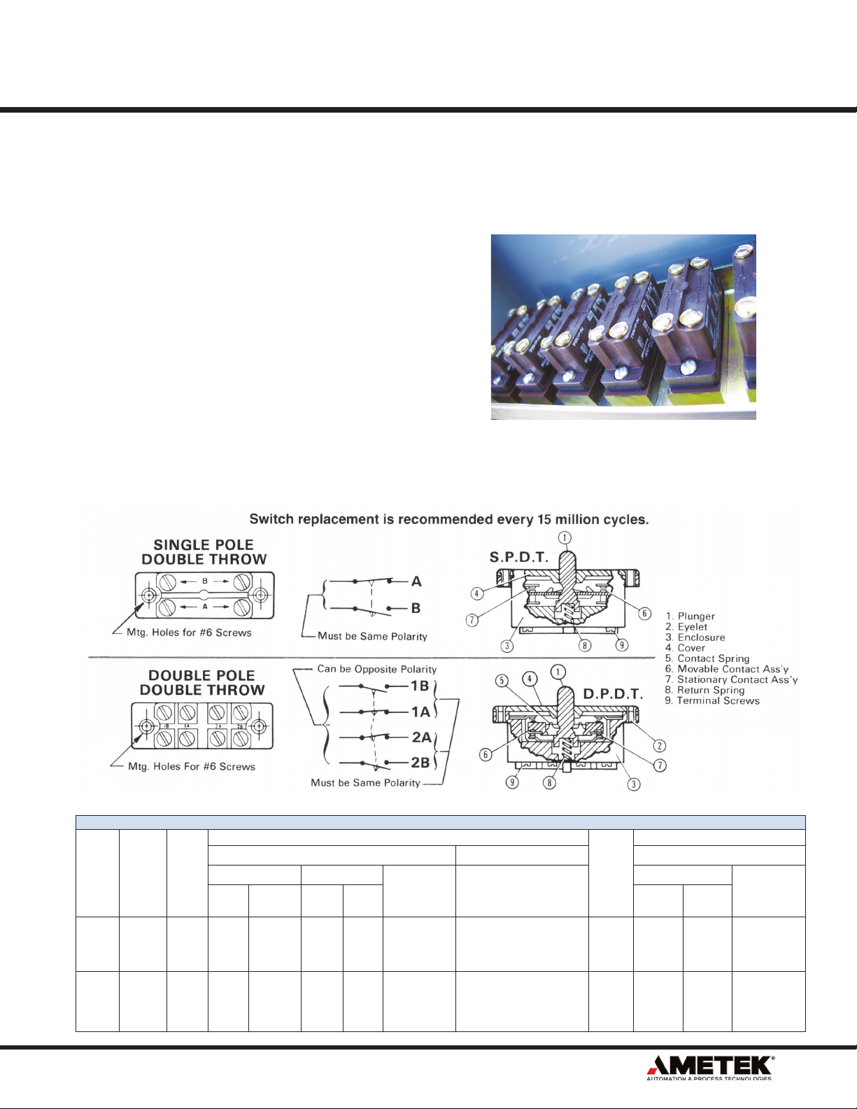
Switch Type
The GEMCO Precision Snap Switches are specifically designed for industrial duty applications where
reliability, ease of wiring and millions of trouble free
cycles are required.
The GEMCO Rotating Cam Limit Switch can be
supplied with either a basic single-pole double-throw
(SPDT), double-pole double-throw (DPDT), or a
combination of both types.
plug-In socket can be supplied with either the
A
SPDT or DPDT switches.
The type of snap switch can be specified in the
catalog numbering system on page 8.
SP
= Single-pole double-throw
DP = Double-pole double throw
SPP = Single-pole double-throw with a plug-in
socket
DPP = Double-pole double-throw with a plug-in socket
The Plug-In Socket eliminates error due to disconnecting and connecting wires during replacement
of the snap switch. A marking strip is supplied with
each plug-in socket for ease of wire identification.
Switch Replacement is Recommended Every
15 Million Cycles.
1080 N. Crooks Road • Clawson, MI 48017-1097 USA • 800.635.0289 • 248.435.0700 • Fax: 248.435.8120 • www.AMETEKAPT.com
9
Page 10

RIGHT ANGLE GEAR REDUCER ROTATION
GEAR REDUCER
POSITION
R1 or L1
R2 or L2
R3 or L3
R4 or L4
R5 or L5
R6 or L6
R7 or L7
R8 or L8
Input Shaft Rotation Versus Cam Shaft Rotation
STRAIGHT
DRIVE GEAR
REDUCER
All Ratios From
1.25:1 to 3:1
All Ratios From
4:1 to 8.5:1
All Ratios From
10:1 to 600:1
All Gear
Multipliers From
1:2 to 1:3
All Gear
Multipliers From
1:4 to 1:8
DETERMINING DIRECTION OF CAMSHAFT — TIMING DIAL ROTATION
Rotation Input Shaft Versus Camshaft
GEAR REDUCER INPUT
SHAFT ROTATION
CW CW
CCW CCW
CW CCW
CCW CW
CW CW
CCW CCW
CW CCW
CCW CW
CW CW
CCW CCW
CW CCW
CCW CW
CW CW
CCW CCW
CW CCW
CCW CW
STRAIGHT DRIVE GEAR REDUCER
GEAR REDUCER
LOCATION OF
INPUT SHAFT
Right End
Left End
Right End
Left End
Right End
Left End
Right End
Left End
Right End
Left End
CAMSHAFT TIMING
DIAL ROTATION
INPUT SHAFT
ROTATION
CW CCW
CCW CW
CW CW
CCW CCW
CW CW
CCW CCW
CW CCW
CCW CW
CW CW
CCW CCW
CW CCW
CCW CW
CW CCW
CCW CW
CW CW
CCW CCW
CW CW
CCW CCW
CW CCW
CCW CW
View Camshaft from
Right End
CW = Clockwise
CCW = Counter Clockwise
CAMSHAFT
TIMING DIAL
ROTATION
View Camshaft from
Right End
10
1080 N. Crooks Road • Clawson, MI 48017-1097 USA • 800.635.0289 • 248.435.0700 • Fax: 248.435.8120 • www.AMETEKAPT.com
Page 11

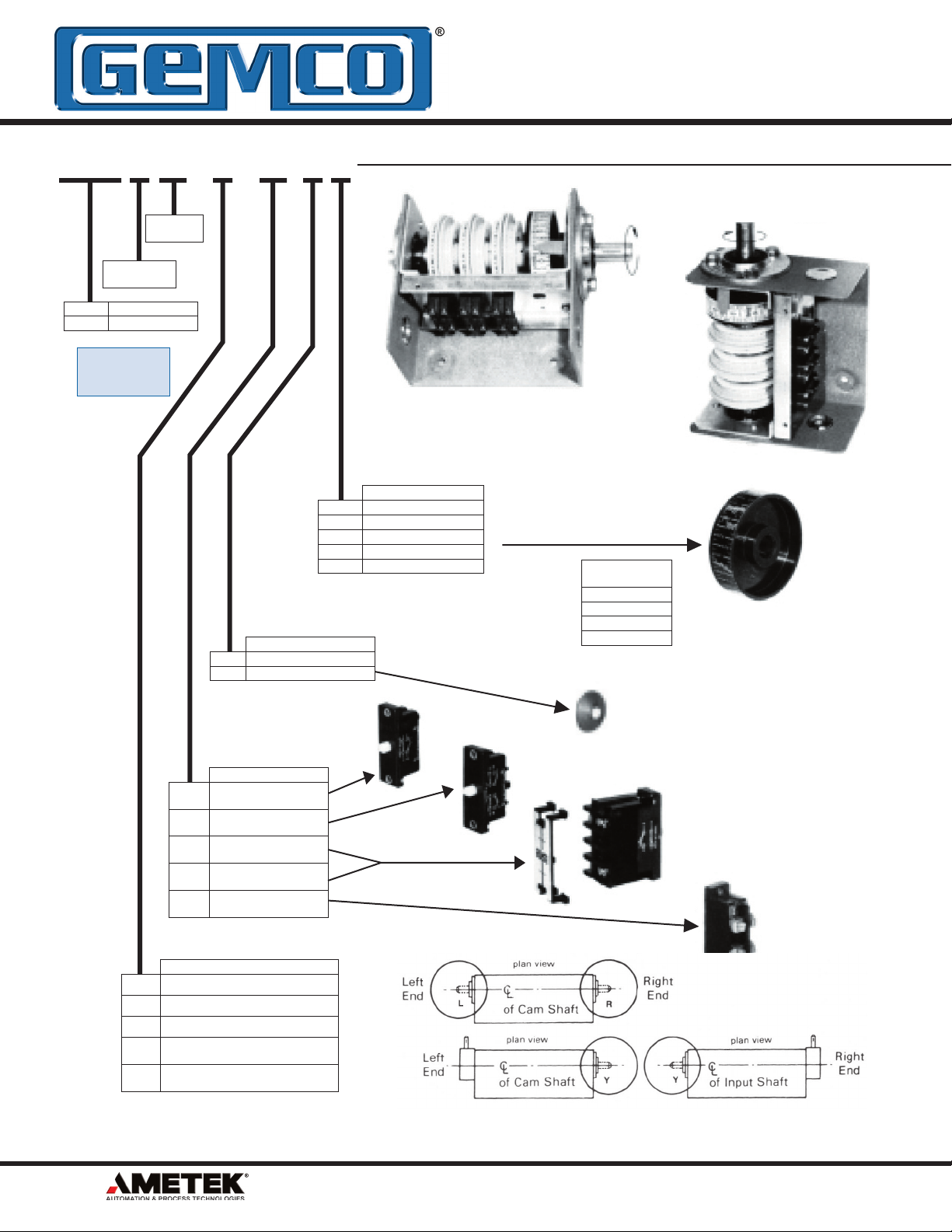
Replacement Cam Assemblies
Standard Cam Assembly
Part No. SD-1178-C
(includes two cams Part Nos. P-356-B and P-357-B)
Blank Cam Assembly
Part No. SD-1140-C
(includes two blank cams Part No. P-271-B)
Special Cams
Blank Cam Assembly (Part No. SD-1140-C) can
A
be supplied in place of the Standard Cam Assembly,
(Part No. SD-1
specified. Advise number required and location.
A drawing of the Cam shape must be given
with the order. Generally, two cams are required
per circuit. When ordering special cut cams, the
customer will supply a detail of the cam profi
the electrical timing chart showing the contact
setting as required.
178-C) at no additional charge, when
le and
Description
The DRIVE-CHEK is a multi-purpose sub base that
is mounted under a chain or belt driven mechanism.
The unit serves three purposes; a broken chain or
belt detector, a chain or belt tightener, and a shock
and vibration isolator.
A GEMCO Indicator Switch is provided with each
DRIVE-CHEK Unit to indicate when a drive belt or
chain failure has occurred. Shock and vibration from
the machine to the hinge plate of the DRIVE-CHEK
Unit are dampened by coil springs on one end of the
hinge plate and an elastomeric support on the other
end.
The springs also maintain a constant tension in
Special Conduit Openings
the drive belt or chain. DRIVE-CHEK is of rugged
welded construction and is painted to prevent
corrosion.
The drive chain or belt can be attached to
the mechanism being driven from either above or
below the DRIVE-CHEK base.
The DRIVE-CHEK base can be purchased as
a separate item for field mounting or factory
assembled to the 1980 camswitch. If factory
installation is desired, order as separate item and
specify as being assembled in the description.
GEMCO single-pole double-throw switch with
A
mounting plate is supplied with each DRIVE-CHEK
Specify conduit size and location.
Unit and can be easily mounted inside the GEMCO
Rotating Cam Limit Switch enclosure. A
double-pole double-throw switch can also be
supplied.
1080 N. Crooks Road • Clawson, MI 48017-1097 USA • 800.635.0289 • 248.435.0700 • Fax: 248.435.8120 • www.AMETEKAPT.com
GEMCO
11
Page 12

B
.34
#606 WOODRUFF KEY
GROOVES TO ACCEPT
GEMCO ADJ. COUPLING
(4 MTG HOLES)
7.94
MIN. VERTICAL
CLEARANCE TO
REMOVE COVER
NOTE:
ASSEMBLY SHOWN IS STANDARD.
SHAFT EXTENSIONS CAN BE PLACED AT
EITHER END OR BOTH ENDS.
E
1.88
4.05
1.50
.7490
.7475
.75
.12
L
AT SHAFT END
(2) HOLES, PLUGGED
CONDUIT SIZE
2.07
A
3.18
D
C
.75
Dia.
Dia.
NEMA 1 Dimensions
No. of Circuits A A-S A-R B C D E L Wt. Approx. Gross
2 to 4 9.28 12.12 9.38 4.42 6.50 5.00 3.12 .75 12 lb.
5 to 6 11.72 14.56 11.82 6.86 6.50
7 to 8 14.16 17.00 14.26 9.30 6.50 5.00 3.12 1.25 16 lb.
9 to 12 19.04 21.88 19.14 14.18 6.50 5.00 3.12 1.25 21 lb.
13 to 16 25.45 28.29 25.55 20.60 7.00 5.50 3.40 2.00 35 lb.
17 to 20 30.33 33.17 30.43 25.48 7.00 5.50 3.40 2.00 46 lb.
21 to 24 35.21 38.05 35.31 30.36 7.00 5.50 3.40 2.00 55 lb.
25 to 28 41.62 44.46 41.72 36.76 7.00 5.50 3.40 2.00
29 to 32 46.50 49.34 46.60 41.64 7.00 5.50 3.40 2.00
33 to 36 51.38 54.22 51.48 46.52 7.00 5.50 3.40 2.00
37 to 40 56.26 59.10 56.36 51.40 7.00 5.50 3.40 2.00
5.00 3.12 1.25 14 lb.
Straight Drive
Ratio X Y Ratio X Y
1.25:1 2.71 2.07 32:1 3.82
2:1 2.63 2.07 35:1 3.82 2.32
2.2:1 3.13 2.07 40:1 3.82 1.88
3:1 2.80 2.07 48:1 3.82 2.01
4:1 4.13 2.07 50:1 3.82 2.07
5:1 4.38 2.07 80:1 3.82 2.44
6:1 4.30 2.07 96:1 3.82 2.32
7:1 4.55 2.07 100:1 3.82 2.07
8:1 4.51 2.07 200:1 3.82 2.07
8.5:1 3.99 2.07 400:1 3.82 1.91
10:1 3.82 1.88 500:1 3.82 1.76
12:1 3.82 2.01 600:1 3.82 2.07
14:1 3.82 2.13 1:2 2.63 2.07
15:1 3.82 2.19 1:3 2.80 2.07
16:1 3.82 2.26 1:4 4.13 2.07
20:1 3.82 1.88 1:5 4.38 2.07
24:1 3.82 2.01 1:6 4.30 2.07
25:1 3.82 2.07 1:7 3.34 2.13
28:1 3.82 2.13 1:8 3.57 2.07
30:1 3.82 2.19
12
1080 N. Crooks Road • Clawson, MI 48017-1097 USA • 800.635.0289 • 248.435.0700 • Fax: 248.435.8120 • www.AMETEKAPT.com
Ratio Y Ratio Y
2.26
1:1 1.00 15:1 1.250
1.2:1 1.375
1.25:1 1.125 17:1 1.368
1.33:1 1.750 18:1 1.437
1.5:1 1.250 20:1 .937
1.6:1 1.625 24:1 1.062
2:1 1.500 25:1 1.875
2.5:1 1.750 28:1 1.187
3:1 2.00 30:1 1.250
4:1 1.875 32:1 1.312
4.75:1 .906 36:1 1.437
5:1 .937 40:1 1.562
6:1 1.062 48:1 1.812
7:1 1.187 50:1 1.875
7.5:1 1.250 60:1 1.156
8:1 1.312 64:1 1.218
10:1 .937 72:1 1.344
12:1 1.062 80:1 1.469
12.5:1 1.875 96:1 1.719
14:1 1.187 100:1 1.781
Right Angle Drive
16:1 1.312
NOTE:
Add 4 lbs. with Right
Angle Gear Reducer.
Add 6 lbs. with
Straight Drive Gear
Reducer.
Page 13

L
AT REDUCER END
(2) HOLES, PLUGGED
CONDUIT SIZE
GROOVES TO ACCEPT
GEMCO ADJ. COUPLING
3.18
REF.
B
6.02
MIN. VERTICAL
CLEARANCE TO
REMOVE COVER
2.07
REF.
1.50
.50
.4995
.4975
E
X
D
Y
4.05
4.86
1.88
.75
#404 WOODRUFF
KEY
.7490
.7475
.34
(4 MTG HOLES)
C
A-S
7.94
NOTE:
ASSEMBLY SHOWN IS STANDARD.
REDUCER CAN BE PLACED ON EITHER END. SHAFT
EXTENSION ON END OPPOSITE OF REDUCER IS OPTIONAL.
Dia.
Dia.
Dia.
.4995
.4975
#404 WOODRUFF
KEY
C
1.68
A-R
Y
2.07
REF
.50
1.50
2.00
.12
GROOVES TO ACCEPT
GEMCO ADJ. COUPLING
2.29
1.16
4.95
REF.
4.05
2.00
2.88
.81
R2, R5, L5, or L8
NOTE: Intrusion below
baseline in positions
7.94
NOTE:
ASSEMBLY SHOWN IS STANDARD.
REDUCER CAN BE PLACED ON EITHER END. SHAFT
EXTENSION ON END OPPOSITE OF REDUCER IS OPTIONAL.
B
MIN. VERTICAL
CLEARANCE TO
REMOVE COVER
.7475
3.18
REF.
.7490
(2) HOLES, PLUGGED
.75
1.88
E
(4 MTG HOLES)
D
.34
AT REDUCER END
L
CONDUIT SIZE
Dia.
Dia.
Dia.
NEMA 1 with Straight Drive Gear Reducer
NEMA 1 with Right Angle Gear Reducer
1080 N. Crooks Road • Clawson, MI 48017-1097 USA • 800.635.0289 • 248.435.0700 • Fax: 248.435.8120 • www.AMETEKAPT.com
13
Page 14

Nema 4 & 5 Dimensions
NOTE:
ASSEMBLY SHOWN IS STANDARD.
SHAFT EXTENSIONS CAN BE PLACED AT
EITHER END OR BOTH ENDS.
#606 WOODRUFF KEY
1.50
3.00
TO REMOVE
ACCESS PLATE
CONDUIT FITTING ON END
L
OPPOSITE SHAFT EXTENSION
H
MIN.
COVER
CLEARANCE
.75
.7490
Dia.
.7475
G
Dia.
.38
(4 MTG HOLES)
B
A
No. of Circuits A A-S A-R B C D E F G H L Wt. Approx. Gross
2 to 4 9.69 12.53 9.78 5.45 10.12 5.00 9.38 2.06 1.58 13.64 .75 18 lb.
5 to 6 12.24 15.08 12.32 7.89 10.12 5.00 9.38 2.06 1.69 13.64 1.25 22 lb.
7 to 8 14.68 17.52 14.78 10.33 10.12 5.00 9.38 2.06 1.69 13.64 1.25 32 lb.
9 to 12 19.56 22.40 19.66 15.21 10.12 5.00 9.38 2.06 1.69 13.64 1.25 50 lb.
13 to 16 26.02 28.86 26.1
17 to 20 30.90 33.73 30.99 26.50 12.12 5.50 11.38 2.81 1.74 15.64 2.00 75 lb.
21 to 24 35.78 38.62
25 to 28 42.19 45.02
29 to 32 47.07 49.91
33 to 36 51.95 54.79
37 to 40 56.83 59.67
2.66
1 21.62 12.12 5.50 11.38 2.81
35.87 31.38 12.12 5.50 11.38 2.81 1.74 15.64 2.00
42.27 37.80 12.12 5.50 11.38 2.81 1.74 15.64 2.00
47.15 42.66 12.12 5.50 11.38 2.81 1.74 15.64 2.00
52.03 47.54 12.12 5.50 11.38 2.81 1.74 15.64 2.00
56.92 52.42 12.12 5.50 11.38 2.81 1.74 15.64 2.00
GROOVES TO ACCEPT
GEMCO ADJ. COUPLING
F
R 4.75
.25
6.00
2.45
E
D
3.25
1.75
.38
C
1.74 15.64 2.00 65 lb.
Straight Drive
Ratio X Y Ratio X Y
1.25:1 4.83 2.45 32:1 5.94 2.64
2:1
2.2:1 5.25 2.45 40:1 5.94 2.26
3:1 4.92 2.45 48:1 5.94 2.39
4:1 6.25 2.45 50:1 5.94 2.45
5:1 6.50 2.45 80:1 5.94 2.82
6:1 6.42 2.45 96:1 5.94 2.70
7:1 6.67 2.45 100:1 5.94 2.45
8:1 6.63 2.45 200:1 5.94 2.45
8.5:1 6.1
10:1 5.94 2.26
12:1 5.94 2.39 600:1 5.94 2.14
14:1 5.94 2.51 1:2 4.75 2.45
15:1 5.94 2.57 1:3 4.92 2.45
16:1 5.94 2.64 1:4 6.25 2.45
20:1 5.94 2.26 1:5 6.50 2.45
24:1 5.94 2.39 1:6 6.42 2.45
25:1 5.94 2.45 1:7 5.46 2.51
28:1 5.94 2.51 1:8 5.69 2.45
30:1 5.94 2.57
14
4.75 2.45 35:1 5.94 2.70
1 2.45 400:1 5.94 2.45
500:1 5.94 2.29
1080 N. Crooks Road • Clawson, MI 48017-1097 USA • 800.635.0289 • 248.435.0700 • Fax: 248.435.8120 • www.AMETEKAPT.com
Right Angle Drive
Ratio Y Ratio Y
1:1 1.00 15:1 1.250
1.2:1 1.375 16:1 1.312
1.25:1 1.125 17:1 1.368
1.33:1 1.750 18:1 1.437
1.5:1 1.250 20:1 .937
1.6:1 1.625 24:1 1.062
2:1 1.500 25:1 1.875
2.5:1 1.750 28:1 1.187
3:1 2.00 30:1 1.250
4:1 1.875 32:1 1.312
4.75:1 .906 36:1 1.437
5:1 .937 40:1 1.562
6:1 1.062 48:1 1.812
7:1 1.187 50:1 1.875
7.5:1 1.250 60:1 1.156
8:1 1.312 64:1 1.218
10:1 .937 72:1 1.344
12:1 1.062 80:1 1.469
12.5:1 1.875 96:1 1.719
14:1 1.187 100:1 1.781
NOTE:
Add 4 lbs. with Right
Angle Gear Reducer.
Add 6 lbs. with
Straight Drive Gear
Reducer.
Page 15

.43
R2, R5, L5, or L8
baseline in positions
NOTE: Intrusion below
Y
NOTE:
ASSEMBLY SHOWN IS STANDARD.
REDUCER CAN BE PLACED ON EITHER END. SHAFT
EXTENSION ON END OPPOSITE OF REDUCER IS OPTIONAL.
2.88
2.00
1.78
A-R
.38
(4 MTG HOLES)
B
G
C
D
CONDUIT FITTING ON END
OPPOSITE GEAR REDUCER
L
.25
3.25
.38
E
2.00
.94
1.50
.75
#606
WOODRUFF
KEY
.7490
.7475
GROOVES TO ACCEPT
GEMCO ADJ. COUPLING
.50
1.50
.4975
.4995
#404 WOODRUFF
KEY
2.88
H
MIN.
COVER
CLEARANCE
2.66 REF
2.00
1.75
2.45
F
6.00
Dia.
Dia.
Dia.
6.00
CONDUIT FITTING ON END
OPPOSITE GEAR REDUCER
3.25
F
E
1.75
L
Y
2.45
2.66 REF
.38
(4 MTG HOLES)
#606
WOODRUFF
KEY
1.50
.75
.7475
.7490
GROOVES TO
ACCEPT GEMCO
ADJ. COUPLING
NOTE:
ASSEMBLY SHOWN IS STANDARD.
REDUCER CAN BE PLACED ON EITHER END. SHAFT
EXTENSION ON END OPPOSITE OF REDUCER IS OPTIONAL.
H
B
.25
MIN.
COVER
CLEARANCE
C
D
.38
G
.50
1.50
#404 WOODRUFF
KEY
.4995
.4975
A-S
X
Dia.
Dia.
Dia.
Nema 4 & 5 with Straight Drive Gear Reducer
Nema 4 & 5 with Right Angle Gear Reducer
1080 N. Crooks Road • Clawson, MI 48017-1097 USA • 800.635.0289 • 248.435.0700 • Fax: 248.435.8120 • www.AMETEKAPT.com
15
Page 16

NEMA 7 Dimensions*
NOTE:
ASSEMBLY SHOWN IS STANDARD.
SHAFT EXTENSIONS CAN BE PLACED AT
EITHER END OR BOTH ENDS.
1-1/4 NPT
CONDUIT HOLE
2.25
.44
Dia.
(4 MTG HOLES)
.50
6.81
B
A
1.50
.75
#606
WOODRUFF
KEY
.7490
Dia.
.7475
GROOVES TO ACCEPT
GEMCO ADJ. COUPLING
7.25
3.00
.52
.50
TYP.
8.62
4.31
13.09
R9.84
TO OPEN
COVER
4.00
.94
No. of Circuits A A-S A-R B
1 to 4 11.12 14.49 11.64 8.62
5 to 8 16.12 19.49 16.64 13.62
9 to 12 21.12 24.49 21.64 18.62
13 to 16 26.12 29.49 26.64 23.62
Straight Drive
Ratio X Y Ratio X Y
1.25:1 5.88 3.00 32:1 6.99 3.19
2:1 5.81 3.00 35:1 6.99 3.25
2.2:1 6.31 3.00 40:1 6.99 2.81
3:1 5.97 3.00 48:1 6.99 2.94
4:1 7.31 3.00 50:1 6.99 3.00
5:1 7.56 3.00 80:1 6.99 3.38
6:1 7.47 3.00 96:1 6.99 3.38
7:1 7.73 3.00 100:1 6.99 3.00
8:1 7.69 3.00 200:1 6.99 3.00
8.5:1 7.17 3.00 400:1 6.99 3.00
10:1 6.99 2.81 500:1 6.99 2.84
12:1 6.99 2.94 600:1 6.99 2.69
14:1 6.99 3.06 1:2 5.81 3.00
15:1 6.99 3.12 1:3 5.97 3.00
16:1 6.99 3.19 1:4 7.31 3.00
20:1 6.99 2.81 1:5 7.56 3.00
24:1 6.99 2.94 1:6 7.47 3.00
25:1 6.99 3.00 1:7 6.52 3.06
28:1 6.99 3.06 1:8 6.75 3.00
30:1 6.99 3.12
* These enclosures are
designed and manufactured
to our interpretation of the
Underwriters Laboratory (UL)
standards (UL 1203, 1994 and
UL 698, 1995), and have not
been submitted for 3rd party
approvals.
16
1080 N. Crooks Road • Clawson, MI 48017-1097 USA • 800.635.0289 • 248.435.0700 • Fax: 248.435.8120 • www.AMETEKAPT.com
Page 17

NOTE:
ASSEMBLY SHOWN IS STANDARD.
REDUCER CAN BE PLACED ON EITHER END. SHAFT
EXTENSION ON END OPPOSITE OF REDUCER IS OPTIONAL.
A-R
1.06
1.56
.75
1.50
.50
2.25
.7490
.7475
#606
WOODRUFF
KEY
B
1-1/4 NPT
CONDUIT HOLE
6.81
.44
(4 MTG HOLES)
#404 WOODRUFF
KEY
TO OPEN
COVER
3.50
1.50
.50
8.62
13.09
Y
7.25
.52
.50
TYP.
3.00
4.31
GROOVES TO ACCEPT
GEMCO ADJ. COUPLING
R9.84
.4975
.94
.4995
Dia.
Dia.
Dia.
13.09
R9.84
TO OPEN
COVER
.94
4.00
GROOVES TO
ACCEPT GEMCO
ADJ. COUPLING
A-S
B
6.81
2.25
(4 MTG HOLES)
.44
.50
1-1/4 NPT
CONDUIT HOLE
1.50
.75
#606
WOODRUFF
KEY
.7475
.7490
7.25
8.62
.50
TYP.
.52
NOTE:
ASSEMBLY SHOWN IS STANDARD.
REDUCER CAN BE PLACED ON EITHER END. SHAFT
EXTENSION ON END OPPOSITE OF REDUCER IS OPTIONAL.
.4995
.4975
1.50
.50
#404 WOODRUFF
KEY
Y
X
Dia.
Dia.
Dia.
NEMA 7 with Straight Drive Gear Reducer
NEMA 7 with Right Angle Gear Reducer
1080 N. Crooks Road • Clawson, MI 48017-1097 USA • 800.635.0289 • 248.435.0700 • Fax: 248.435.8120 • www.AMETEKAPT.com
17
Page 18

NEMA 12 Dimensions
NOTE:
ASSEMBLY SHOWN IS STANDARD.
SHAFT EXTENSIONS CAN BE PLACED AT
EITHER END OR BOTH ENDS.
#606 WOODRUFF KEY
1.50
.75
.7490
.7475
Dia.
.50 TYP.
CONDUIT FITTING
L
ON END OPPOSITE
SHAFT EXTENSION
10.38
MIN. VERTICAL
CLEARANCE TO
REMOVE COVER
5.44
F
Dia.
.38
(4 MTG HOLES)
G
B
A
No. of Circuits A A-S A-R B C D E L Wt. Approx. Gross
2 to 4 9.28 12.12 9.38 4.42 6.50 5.00 3.12 .75 12 lb.
5 to 6 11.72 14.56 11.82 6.86 6.50
7 to 8 14.16 17.00 14.26 9.30 6.50 5.00 3.12 1.25 16 lb.
9 to 12 19.04 21.88 19.14 14.18 6.50 5.00 3.12 1.25 21 lb.
13 to 16 25.45 28.29 25.55 20.60 7.00 5.50 3.40 2.00 35 lb.
17 to 20 30.33 33.17 30.43 25.48 7.00 5.50 3.40 2.00 46 lb.
21 to 24 35.21 38.05 35.31 30.36 7.00 5.50 3.40 2.00 55 lb.
25 to 28 41.62 44.46 41.72 36.76 7.00 5.50 3.40 2.00
29 to 32 46.50 49.34 46.60 41.64 7.00 5.50 3.40 2.00
33 to 36 51.38 54.22 51.48 46.52 7.00 5.50 3.40 2.00
37 to 40 56.26 59.10 56.36 51.40 7.00 5.50 3.40 2.00
2.66
GROOVES TO ACCEPT
GEMCO ADJ. COUPLING
.25
E
3.25
D
C
5.00 3.12 1.25 14 lb.
2.45
.38
Straight Drive
Ratio X Y Ratio X Y
1.25:1 2.71 2.07 32:1 3.82
2:1 2.63 2.07 35:1 3.82 2.32
2.2:1 3.13 2.07 40:1 3.82 1.88
3:1 2.80 2.07 48:1 3.82 2.01
4:1 4.13 2.07 50:1 3.82 2.07
5:1 4.38 2.07 80:1 3.82 2.44
6:1 4.30 2.07 96:1 3.82 2.32
7:1 4.55 2.07 100:1 3.82 2.07
8:1 4.51 2.07 200:1 3.82 2.07
8.5:1 3.99 2.07 400:1 3.82 1.91
10:1 3.82 1.88 500:1 3.82 1.76
12:1 3.82 2.01 600:1 3.82 2.07
14:1 3.82 2.13 1:2 2.63 2.07
15:1 3.82 2.19 1:3 2.80 2.07
16:1 3.82 2.26 1:4 4.13 2.07
20:1 3.82 1.88 1:5 4.38 2.07
24:1 3.82 2.01 1:6 4.30 2.07
25:1 3.82 2.07 1:7 3.34 2.13
28:1 3.82 2.13 1:8 3.57 2.07
30:1 3.82 2.19
18
1080 N. Crooks Road • Clawson, MI 48017-1097 USA • 800.635.0289 • 248.435.0700 • Fax: 248.435.8120 • www.AMETEKAPT.com
2.26
Right Angle Drive
Ratio Y Ratio Y
1:1 1.00 15:1 1.250
1.2:1 1.375 16:1 1.312
1.25:1 1.125 17:1 1.368
1.33:1 1.750 18:1 1.437
1.5:1 1.250 20:1 .937
1.6:1 1.625 24:1 1.062
2:1 1.500 25:1 1.875
2.5:1 1.750 28:1 1.187
3:1 2.00 30:1 1.250
4:1 1.875 32:1 1.312
4.75:1 .906 36:1 1.437
5:1 .937 40:1 1.562
6:1 1.062 48:1 1.812
7:1 1.187 50:1 1.875
7.5:1 1.250 60:1 1.156
8:1 1.312 64:1 1.218
10:1 .937 72:1 1.344
12:1 1.062 80:1 1.469
12.5:1 1.875 96:1 1.719
14:1 1.187 100:1 1.781
NOTE:
Add 4 lbs. with Right
Angle Gear Reducer.
Add 6 lbs. with
Straight Drive Gear
Reducer.
Page 19

2.66 REF
2.00
G
.38
D
C
.25
B
2.45
E
F
3.25
Y
2.88
2.00
NOTE: Intrusion below baseline in positions
R2, R5, L5, or L8
.43
.94
1.78
A-R
.38
(4 MTG HOLES)
CONDUIT FITTING ON END
OPPOSITE GEAR REDUCER
L
2.00
1.50
.75
#606
WOODRUFF
KEY
.7490
.7475
GROOVES TO ACCEPT
GEMCO ADJ. COUPLING
.50
1.50
.4975
.4995
#404 WOODRUFF KEY
2.88
NOTE:
ASSEMBLY SHOWN IS STANDARD.
REDUCER CAN BE PLACED ON EITHER END. SHAFT
EXTENSION ON END OPPOSITE OF REDUCER IS OPTIONAL.
5.44
Dia.
Dia.
Dia.
CONDUIT FITTING
ON END OPPOSITE
SHAFT EXTENSION
3.25
F
E
2.45
L
B
.25
C
D
G
5.44
1.50
.50
.4995
.4975
#404 WOODRUFF
KEY
GROOVES TO
ACCEPT GEMCO
ADJ. COUPLING
2.66 REF
A-S
Y
X
.38
.7490
.7475
.75
#606
WOODRUFF
KEY
1.50
.38
(4 MTG HOLES)
MIN. VERTICAL
CLEARANCE TO
REMOVE COVER
.50 TYP
10.38
NOTE:
ASSEMBLY SHOWN IS STANDARD.
REDUCER CAN BE PLACED ON EITHER END. SHAFT
EXTENSION ON END OPPOSITE OF REDUCER IS OPTIONAL.
Dia.
Dia.
Dia.
NEMA 12 with Straight Drive Gear Reducer
NEMA 12 with Right Angle Gear Reducer
1080 N. Crooks Road • Clawson, MI 48017-1097 USA • 800.635.0289 • 248.435.0700 • Fax: 248.435.8120 • www.AMETEKAPT.com
19
Page 20

AMETEK APT Products
Copyright 2005 by AMETEK AUTOMATION & PROCESS TECHNOLOGIES. All Rights Reserved. Made in the USA.
1080 N. Crooks Road, Clawson, MI 48017
Phone: 248.435.0700 Toll Free: 800.635.0289
Fax: 248.435.8120 www.AMETEKAPT.com
1980.C4R
10/08.Z11
 Loading...