

Page 1
Series 1970
Gemco
™
Drive-Chek
TM
Control Catalog
. . . OFFERS ENGINEERED PROTECTION FROM . . .
• BROKEN DRIVE CHAINS
• VIBRATION
• LOOSE DRIVE CHAINS
• SHOCK DAMAGE
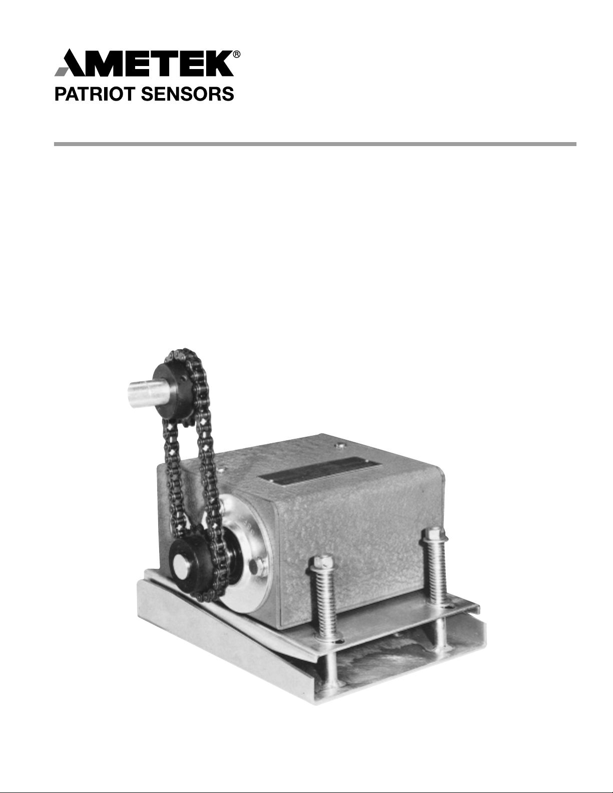
DRIVE-CHEK
WITH GEMCO ROTATING
CAM LIMIT SWITCH
Page 2
2
DESCRIPTION
The DRIVE-CHEK is a multi-purpose sub base that is
mounted under a chain or belt driven mechanism. The unit
serves three purposes; namely, a broken chain or belt
detector, a chain or belt tightener, and a shock and vibration
isolator.
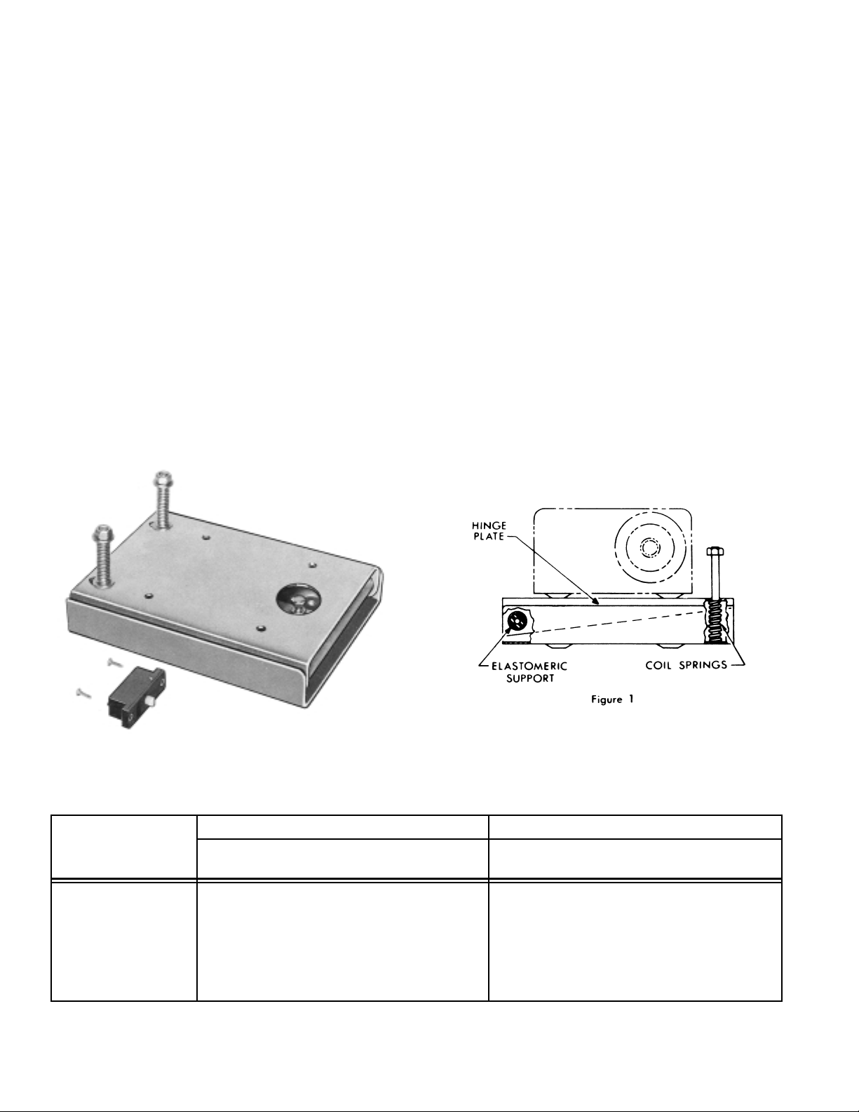
A Gemco Indicator Switch is provided with each DRIVE-
CHEK Unit to indicate when a drive belt or chain failure has
occurred. Shock and vibration from the machine to the
hinge plate of the DRIVE-CHEK Unit are dampened by coil
springs on one end of the hinge plate and an elastomeric
support on the other end.
The springs also maintain a constant tension in the drive
belt or chain. DRIVE-CHEK is of rugged welded construction and is painted to prevent corrosion. The drive chain or
belt can be attached to the mechanism being driven from
either above or below the DRIVE-CHEK base.
The mounting and set up procedures for the DRIVE-CHEK
Indicator Switch and the location of the coil springs are outlined on pages 4 and 5.
DRIVE-CHEK INDICATOR SWITCH
Function and Installation
A Gemco single pole double throw switch with mounting
plate is supplied with each DRIVE-CHEK Unit and can be
easily mounted inside the Gemco Rotating Cam Limit
Switch enclosure. A Gemco double pole double throw
switch can also be supplied at additional cost.
Three holes are drilled in the base of the Rotating Cam Limit
Switch (see pages 6 and 7 for size and location) to mount
the DRIVE-CHEK Indicator Switch. After the unit is mount-
ed on the machine with the Rotating Cam Limit Switch and
drive chain in place, the two coil springs between the stationary and movable part of the unit will be compressed to
nearly their solid height.
The indicator switch is then adjusted to be engaged. If the
chain breaks or runs off its sprockets, the coil springs will
raise the hinge plate and the indicator switch will be disengaged (when the drive is below the hinge plate). The switch
would be wired into the control circuit of the machine drive
to stop the machine.
When ordering the DRIVE-CHEK Unit with the Gemco
Rotating Cam Limit Switch, there will not be any additional
charge for drilling the holes in the Rotating Cam Limit Switch
enclosure for the Gemco Indicator Switch.
1980 NEMA 1 1980 NEMA 4 and 12
No. of
Circuits Catalog Number Catalog Number
2 – 4 1970-104 1970-1204
5 – 6 1970-106 1970-1206
7 – 8 1970-108 1970-1208
9 – 12 1970-112 1970-1212
13 – 16 1970-116 1970-1216
17 – 20 1970-120 1970-1220
21 – 24 1970-124 1970-1224
Addition Replacement indicator switch
S.P.D.T. Cat. No. 1950-1404
D.P.D.T. Cat. No. 1950-1405
DRIVE-CHEK for Gemco Catalog Section
1980 Rotating Cam Limit Switches*
Page 3

3
1. Align Drive Sprockets and mount DRIVE-CHEK
base using 5/16" bolts.
2. Engage proper length drive chain to allow hinge
plate to be parallel to the base when drive chain
is tight.
3. Attach flexible conduit to allow free movement of
the hinge plate.
4. Set switch adjustment bolt to engage indicator
switch if the drive chain breaks.
5. Tighten adjustment bolt locknut.
6. Assemble springs with washers on each end of
the coil springs and self-locking nuts. The springs
should be compressed to nearly solid height.
7. Check the movement of the hinge plate to insure
that the conduit and chain guard does not restrict
the hinge plate from tripping the DRIVE-CHEK
Indicator Switch.
MOUNTING and SET-UP for GEMCO DRIVE-CHEK
with DRIVE CHAIN UNIT
1 2
3 4
5 6
6A
6A - Drive chain below is the same procedure to
install
Page 4

1970.C1
4/99 • Z26
1M
DRIVE-CHEK DIMENSIONS FOR SERIES 1980
NEMA 1 NEMA 4 and 12
NO. OF
ABCD
CIRCUITS
2-4 7.31 4.42 5.00 9.75
5-6 9.75 6.86 5.00 9.75
7-8 12.19 9.30 5.00 9.75
9-12 17.07 14.18 5.00 9.75
13-16 23.48 20.60 5.50 10.25
17-20 28.36 25.48 5.50 10.25
21-24 33.24 30.36 5.50 10.25
NO. OF
ABCD
CIRCUITS
2-4 7.31 4.42 5.00 11.40
5-6 9.75 6.86 5.00 11.40
7-8 12.19 9.30 5.00 11.40
9-12 17.07 14.18 5.00 11.40
13-16 23.48 21.62 7.00 13.40
17-20 28.36 26.50 7.00 13.40
21-24 33.24 31.38 7.00 13.40
Dimensions shown apply
when platform and base
are parallel.
1080 NORTH CROOKS ROAD • CLAWSON, MI 48017 USA
800-635-0289 • 248-435-0700 • Fax 248-435-8120
www.patriotsensors.com • www.ametek.com
 Loading...