

Page 1
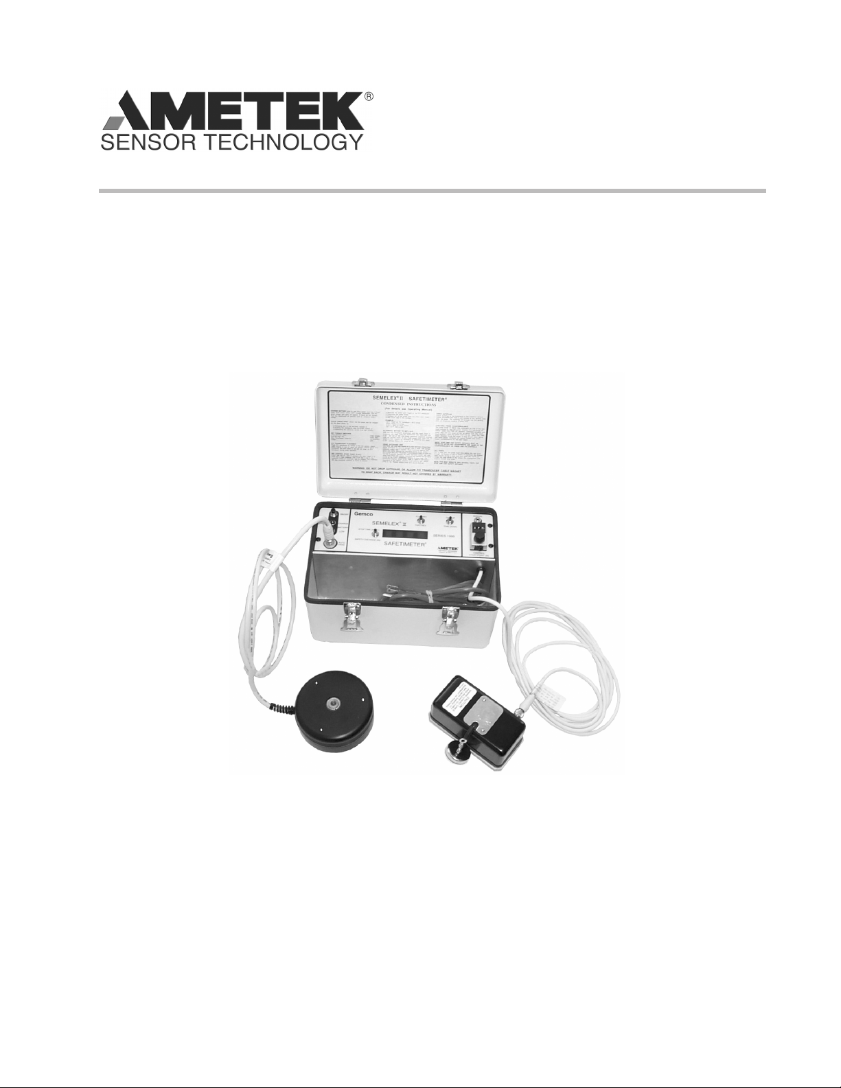
Semelex IITM Safetimeter
Operating Manual
Series 1999
TM
Gemco
Self-Contained, Portable Electronic Stop-Time Meter
Page 2

.
Page 3

1080 North Crooks Road
Clawson, MI 48017-1097
Phone: (248) 435-0700
FAX: (248) 435-8120
Internet: www.ametek.com www.ameteksensortech.com
Preface
This manual will instruct user in operating the Gemco 1999 Semelex II Safetimeter.
Copyright 1999 by AMETEK Sensor Technology
All Rights Reserved - Made in the U.S.A.
Version 0.1
AMETEK has checked the accuracy of this manual at the time it was printed. Any
comments you may have for the improvement of this manual are welcomed.
AMETEK reserves the right to revise and redistribute the entire contents or selected
pages of this manual. All rights to the contents of this manual are reserved by AMETEK.
iInstallation & Programming Manual
Page 4

Contents
Chapter 1: Overview 1
1.1 Safetimeter Switches and Connectors.................................................1
1.2 Theory of Operation............................................................................2
Chapter 2: Unpack & Set-Up 3
2.1 Set-Up and Test .................................................................................3
Chapter 3: Operating Instructions 5
3.1 Placement of Position/Velocity (P/V) Transducer ................................5
3.2 Set the Control Start Point (CSP) ........................................................5
3.3 Set the TIME UP/TIME DOWN Switch ................................................7
3.4 Using Auto-Hand ...............................................................................8
3.5 Using Auto-Flag with Auto-Hand ........................................................9
3.6 Using Optional Manual Start Switches .............................................10
3.7 Using Optional Remote Tachometer..................................................10
3.8 Calculate Stop Angle ........................................................................11
3.9 Using the Safetimeter to Aid in Setting Cam Limit Switch Brake-
Monitors...........................................................................................13
3.10 Test Presses Running in a Continuous Mode ....................................14
3.11 Set Press Counterbalance.................................................................15
3.12 Test Full Revolution Clutch Presses..................................................16
Chapter 4: Certifi cation and Warranty 17
4.1 Optional 5 Year Warranty.................................................................17
Chapter 5: Specifi cations 18
Installation & Programming Manualii
Page 5

Chapter 1: Overview
Chapter 1: Overview
The Series 1999 Semelex II Safetimeter is a self-contained, portable electronic stop
time meter capable of measuring elapsed time, stop time (Ts) from 1-9999 milliseconds.
It also calculates the minimum safety distance (Ds) based on the OSHA formula, as
understood by the factory, and will display up to 999.9 inches to the nearest 0.1
inches.
The Semelex II Safetimeter Test Set consists of four components:
Safetimeter This is the “brains” of the unit, with processing electronics
that display the test results.
Position/Velocity (P/V) This motion and position sensor attaches to the press with
Transducer its base and cable magnets.
Auto-Hand (A/H) This hand-held device is used to automatically release a run
control or press an E-Stop control on the press.
Auto-Flag (A/F) This assembly is attached to the Auto-Hand to test presses
equipped with electronic guards, i.e. photoelectric barrier
guards (light curtains) or capacitance type guards (conduit
rail sensors).
Option:
Manual Start Switches These two switches plug into the MANUAL START jack on the
Safetimeter panel and are used to manually start the
Safetimeter timing.
Option:
Remote Tachometer The tachometer replaces the P/V Transducer and Auto-Hand
with Base when testing high speed or continuous stroke presses that
can’t stop within one stroke. With the wheel attachment, it
can be used to test conveyors or indexing tables.
1.1: Safetimeter Switches and Connectors
ON/OFF This is the unit’s power switch. In the ON or OFF position
the power cord may be plugged into 115 VAC outlet for
recharging the battery. In the ON position, the unit may be
operated from the internal battery or 115 VAC line.
NOTE: With the Safetimeter ON and plugged in, the battery charges at a lower rate.
Operating Manual
1
Page 6

Chapter 1: Overview
TIME UP/TIME DOWN This switch determines the direction of the test. In the
TIME DOWN position you are performing a standard test
according to OSHA requirements. The switch should be in
the TIME UP position when checking press top stop.
STOP TIME (mSEC)/ This switch is used to select the display mode, either time or
SAFETY DISTANCE (IN) distance. Time is measured in milliseconds and distance is
measured in inches.
FULL REV/PART REV This switch is used to determine the press clutch operation
mode, either full or part revolution. The majority of tests
are run in the part revolution mode.
CONTROL START Known as CSP, this dial is used to set the point in the
POINT (IN) stroke at which the command to start timing and fi res
the Auto-Hand is given. When the CSP dial is turned
clockwise, the dial will increment and de-increment when
turned counterclockwise. The CSP dial reads in tenths of
an inch. Example: 123 equals 12.3”.
MANUAL START This jack is used with the optional manual start switches.
AUTO-HAND This connector is used to connect the Auto-Hand to the
Safetimeter.
1.2: Theory of Operation
The P/V transducer measures the open height of a press. When this measurement
coincides with the preset CSP position, and the ram is traveling in the direction
selected on the TIME UP/TIME DOWN switch, the Auto-Hand will release one of the
two run controls or press an E-STOP control to initiate the press stop. When the
ram stops, the P/V transducer sends a stop signal to the Safetimeter and the meter
displays either stop time or safety distance, whichever display mode was selected
prior to the test.
NOTE: No OSHA standard exists for defi ning when a press has stopped (at what
ram velocity). The Safetimeter ends its measurement when the ram velocity
is approximately .17 inches per second (10 inches per minute). When
measuring stop time, you must take into account all elements and devices
used to bring the ram to rest. These include the “fl ight time” of the run and
E-STOP buttons (time for switch to activate), control relays, solenoids valves
and clutch and brake mechanical elements. Where an electronic guard (light
curtain) is used, response time of the device and the depth penetration factor
must be added to that measured by the Safetimeter before calculating safety
distance. Response time is generally stated by manufacturers of electronic
guards. However, to verify systems, the Auto-Flag can be used.
2
Operating Manual
Page 7

Chapter 2: Unpack & Set-Up
Chapter 2: Unpack & Set-up
The Series 1999 Semelex II Safetimeter has been carefully inspected and tested before
shipment. Unpack the unit and perform a visual inspection to assure that no damage
has occurred during shipping. If damage is found, notify the transportation company
immediately. Only the consignee may institute a claim with the carrier for damage
during shipment.
2.1: Set-Up and Test
1. The Safetimeter battery is shipped with a partial charge. Plug in the unit
and charge the battery until the green LED goes off (maximum charge time
is eight (8) hours).
2. Connect the P/V transducer with the appropriate connector.
3. Make the following Safetimeter switch settings:
Display SAFETY DISTANCE (IN)
Revolution PART REV
Timing Direction TIME DOWN
Control Start Point (CSP) 200 (20.0 inches)
4. Push the ON/OFF switch ON.
5. Place the P/V transducer on a metal desk or steel plate. The magnetic base
will hold the unit in place.
6. Carefully slide the cable magnet from its keeper. Do not let the cable run
free, it can be damaged by impact from sudden release. Pull the cable magnet
out approximately 24 inches.
7. Bring the magnet back towards the P/V transducer. The P/V transducer
will reel in the cable automatically. When the cable magnet is about 20
inches from the base of the P/V transducer, the Safetimeter will start
counting. The unit will continue counting as long as the cable velocity is .17
inch per second (10 inches/minute) or greater.
8. Stop the cable from rewinding or pull the magnet out. The display will stop
incrementing and show the results.
9. Again, pull the cable out approximately 24 inches. The display’s current value
will remain because the Safetimeter is set in the TIME DOWN direction.
10. Let the cable rewind. The display will reset to “0” and start counting. The
zero reset occurs automatically at the beginning of the count and cannot
be seen.
NOTE: The Safetimeter will count when the cable is rewinding and stop when the
cable stops or the direction is reversed.
Operating Manual
3
Page 8

Chapter 2: Unpack & Set-up
11. Change the TIME UP/TIME DOWN switch to the TIME UP position and start
with the cable rewound. The Safetimeter will begin to count when the 20 inch
CSP setting is reached and continue until the cable stops or the direction is
reversed.
12. Set the CSP dial to several values and check that the Safetimeter begins to
count at the preset positions when the cable is moving in the direction selected
by the TIME UP/TIME DOWN switch.
13. If the optional Manual Start Switches are available, continue with steps 14-15.
If not, move to Chapter 3: Operating Instructions.
14. Plug one of the Manual Start Switches in the MANUAL Start jack. If the
Safetimeter is ON, the counter will begin to run. Switch the Safetimeter OFF
and then ON to reset the counter.
15. If the Manual Start Switch is normally closed (red plug), the Safetimeter will
begin to count when the switch is pushed. If the Manual Start Switch is
normally open (black plug), the Safetimeter will begin to count when the switch
is released.
4
Operating Manual
Page 9

Chapter 3: Operating Instructions
Chapter 3: Operating Instructions
3.1: Placement of Position/Velocity (P/V) Transducer
1. Position the magnetic base of the P/V transducer on a clean area of the
press’s bed or bolster plate.
2. Extend the cable magnet to the ram in a straight line, perpendicular to the
transducer and attach the magnet to the ram. A test will not start at 90
degrees if the cable is angled.
3. Connect the P/V transducer to the Safetimeter using the cable provided.
CAUTION: Never place the transducer where the press or dies can close in on
it. Also, be sure when the press closes, the transducer still has some
cable extended to keep it from slamming the magnet into the body of
the transducer.
3.2: Set the Control Start Point (CSP)
There are three ways to set the CSP depending on the following conditions. Proceed to
the section that best fi ts your condition.
A. Setting the CSP dial when the press stroke is known.
B. Setting the CSP dial when the press stroke is not known.
C. Setting the CSP dial at the 90 degree crankshaft position.
A . Setting the CSP dial when the press stroke is known.
1. Raise the press to the top of its stroke.
2. a. Set the TIME UP/TIME DOWN switch to TIME DOWN position.
b. Set the FULL REV/PART REV switch to PART REV.
c. Select either STOP TIME (mSEC) or SAFETY DISTANCE (IN) display.
3. Switch on the Safetimeter.
4. Turn the CSP dial clockwise until the Safetimeter begins to count.
5. Switch the Safetimeter OFF and then ON to stop the counter.
Operating Manual
5
Page 10

Chapter 3: Operating Instructions
6. Turn the CSP dial counterclockwise somewhere below the reading where the Safetimeter began
to count.
7. Slowly turn the CSP dial clockwise and stop when the Safetimeter begins to count. The
number displayed in the CSP dial is the distance between the base of the P/V transducer and
the ram.
8. Subtract 1/2 of the press stroke from the number displayed in the CSP dial to calculate the
Control Start Point.
Example: If the number displayed in the CSP dial is 240 (24.0”) and the press stroke is 6”, subtract 3”
(1/2 stroke) from 24.0” equals 21.0”. This is the mid-stroke position. While it may not represent the
exact 90 degree point of the crankshaft, it is close. This electronically measured point in the stroke will
start the Safetimeter, and fi res the Auto-Hand.
9. Set the CSP dial to the result of Step 8. From the example, the CSP dial would be set to 210
(21.0”)
B. Setting the CSP dial when the press stroke is not known.
1. Find the open height of the press by performing steps 1-7 in subsection (A). Record the
distance determined in step 7.
2. Lower the press ram to the bottom of the stroke. Find the closed height of the press by
performing steps 2-7 in subsection (A). Record the distance determined in step 7.
3. Using the two distances determined from steps 1 and 2, calculate the mid-stroke position using
the following method: Add the two measurements together and divide by two (2).
Example: Midstroke = (Open Height + Closed Height) ÷ 2
4. Set the CSP dial to the above result.
C. Setting the CSP dial at the 90 degree crankshaft position.
To test at the 90 degree crankshaft position, or when the P/V Transducer cable is angled, the CSP will
act as a reference setting.
1. Inch the press to 90 degrees by observing the crankshaft or stroke indicator.
2. Perform steps 2-7 in subsection (A).
6
Operating Manual
Page 11

Chapter 3: Operating Instructions
3. The distance determined in step 7 (number displayed on the CSP dial) is the 90
degree point of the crankshaft, which includes allowance for the cable angle.
NOTE: When testing the top stop, the distance determined in step 3 will correspond
to the 270 degree position of the crankshaft when the TIME UP/TIME DOWN
switch is in the TIME UP position.
3.3: Set the TIME UP/TIME DOWN Switch
The TIME UP/TIME DOWN switch is used to select the direction the press (closing
or opening) is moving when the automatic stop command is given. This switch must
be properly set even when a manual test, with the optional manual start switches,
is performed.
NOTE: The Gemco Semelex II Safetimeter has the capability to check both down and
up stop times to aid in setting the press counterbalance.
For best results, the down stop time test should be initiated at 90 degrees, and the
up stop time should be initiated at 270 degrees. During these tests, it is important to
stop the ram before the dies engage on the down stoke and before top dead center on
the up stroke. On some presses, however, the ram may take more than 90 degrees to
come to a complete stop. If so, adjust the CSP as follows:
1. On the down stop time test, increase the Control Stop Point (CSP) setting to
initiate a stop between 0 and 90 degrees. Continue increasing the CSP and
testing the press until the ram can be stopped before the dies engage.
2. Similarly, on the up stop time test, decrease the CSP setting to initiate a stop
between 180 and 270 degrees. Continue decreasing the CSP and testing the
press until the ram can be stopped before top dead center.
It is important to test both the down and up stop times using the same press control.
Typically, an inch button or two-hand control in the inch mode is used since the up
stop time test is not possible in the single-stroke mode with two hand controls.
Adjusting the counterbalance air pressure to obtain near equal down and up stop
times will set the counterbalance at is optimum point.
NOTE: Always follow the press manufacturer’s recommendations for setting the
counterbalance. Several down stroke Safety Distance and/or Stop Time tests
must be performed after setting the counterbalance to ensure proper press
operation and guarding.
Operating Manual
7
Page 12

Chapter 3: Operating Instructions
3.4: Using Auto-Hand
The Auto-Hand is designed to release or push press controls. It can release a twohand control or inch button, or push an E-Stop button. Auto-Hand is not required if
you are using one of the optional Manual Start Switches.
Using Auto-Hand with Two Hand or Inch Control (Release to Stop)
The Auto-Hand releases or pushes buttons with a spring-loaded plunger. When the
plunger is pushed, it will latch into position. The Safetimeter provides a voltage pulse
to energize a solenoid that releases the spring loaded plunger. If the two-hand control
has a ring guard, the Auto-Hand should rest on the guard and the three support
legs are not needed.
1. Connect Auto-Hand to the Safetimeter. Depress the plunger and place the
extended end over one of the two-hand buttons. Rest Auto-Hand on the
button’s ring guard. If no ring guard exists, screw in the three legs to serve as a
rest. Use your other hand to press the other button.
2. Cycle the press. The Auto-Hand will actuate when the desired CSP is reached,
releasing the button and initiate a press stop.
NOTE: The Auto-Hand can only release 10 lbs. of force and may not release if pushed
against the button with excessive force. In this case, use one leg as a spacer,
to prevent applying excessive force. Place over switch and repeat step 2.
NOTE: Be sure the press has stopped before the bottom of the stroke. Readings are
invalid if the press goes through the bottom of the stroke before stopping. If
this happens, increase the CSP setting slightly until the press stops before
the bottom.
3. Remove Auto-Hand and restart the press to return the ram to top stop.
4. Read the Safetimeter display. This value is the Stop Time or Safety Distance,
depending on the display mode selected prior to the test.
Using Auto-Hand with and E-STOP Button (Push to Stop)
1. Screw the plunger extension into the plunger end that retracts when the
plunger is depressed. This end is used to push an E-STOP button. Attach the
three legs to this side, if required.
2. With the Auto-Hand plunger depressed, place the unit over the E-STOP button
to be
pushed. Check that the plunger extension is adjusted out far enough to push the
button when the Auto- Hand releases.
8
Operating Manual
Page 13

Chapter 3: Operating Instructions
3. Position the Auto-Hand over the E-STOP button. The plunger extension should
not touch the E-STOP button.
4. Cycle the press while holding Auto-Hand over the button. Auto-Hand will
operate when the desired CSP is reached and push the E-STOP button, stopping
the press.
3.5: Using Auto-Flag with Auto-Hand
Auto-Flag is used in conjunction with Auto-Hand to test the entire press control loop
which includes electronic guards, i.e. photoelectric barrier guards (light curtains) or
capacitance type guards (conduit rail sensor).
This test initiates a press stop by obstructing the sensing area with Auto-Flag,
causing the guard to activate a stop signal in the press.
Attaching Auto-Flag to Auto-Hand
1. Screw the Auto-Flag into the retracted end of the plunger when the Auto-Hand
plunger is depressed. Adjust the Auto-Flag so that it is just outside of the
light curtain.
2. Rest the Auto-Hand with Auto-Flag against the light curtain enclosure just
outside the sensing area.
3. Now, set up the Safetimeter and the P/V Transducer as described earlier to
run a test.
4. Cycle the press. When the ram crosses the 90 degree point (position in the
stroke desired to initiate a press stop), the Auto-Hand will release the fl ag into
the sensing area initiating a press stop.
NOTE: During this test, verify that when the press stops, the dies have not fully
engaged and the press has not gone through the bottom of its
stroke. If either situation occurs, increase the CSP setting slightly
and repeat the test. The displayed stop time is the total of the
electronic guard delay plus press control and braking effectiveness.
If desired, the OSHA formula for safety distance can be read directly from
the Safetimeter display. Set the STOP TIME/SAFETY DISTANCE switch
to SAFETY DISTANCE prior to the test. Presses using electronic
guards have other mandated control requirements (brake monitors,
for example) which should be in place and operating correctly.
When determining SAFETY DISTANCE for light curtains, the depth
penetration factor must be added to the Safetimeter reading.
Operating Manual
9
Page 14

Chapter 3: Operating Instructions
3.6: Using Optional Manual Start Switches
The Safetimeter can be used in a manual mode with one of two optional Manual
Start Switches. These switches are plugged into the MANUAL START jack on the
Safetimeter panel. No wiring to the press control is required.
1. Normally Open Switch (PSD0110400). Designated with a black plug. Used over
an inch button or two-hand control, this switch starts the Safetimeter when
released.
2. Normally Closed Switch (PSD0110309). Designated with a red plug. Used over
an E-STOP button, this switch starts the Safetimeter timing when pressed.
Perform the following Steps:
1. Set the TIME UP/TIME DOWN, FULL REV/PART REV, and STOP TIME/SAFETY
DISTANCE switches as required.
2. Mark the ram or slide and frame with chalk, paint, etc. at the 90 degree point.
3. When the marks are aligned during the stroke of the press, release or push the
Manual Start Switch being used. This takes practice to get into sync with the
press. Ten to 20 strokes may be needed. Be sure the readings are fairly
repetitive. Using the Manual Start Switches is less accurate than Auto-Hand.
3.7: Using Optional Remote Tachometer
For testing continuous stroke or high speed presses perform the following steps:
1. Connect the Remote Tachometer to the P/V Transducer cable in the Safetimeter
case.
2. Position the Remote Tachometer on the press (machine) with the magnetic
base. Center the rubber nose cone on the rotating shaft, such as a press’s
crankshaft or cam switch shaft. Good axial alignment is needed.
NOTE: If the shaft rotation, viewed by the tachometer, is clockwise, toggle the TIME
UP/TIME DOWN switch to TIME UP. If the shaft rotation is counterclockwise,
toggle the switch to TIME DOWN. Toggle the STOP TIME/SAFETY DISTANCE
switch to STOP TIME.
3. If the press is to be tested from the E-STOP button, use the normally closed
(red) Manual Start Switch. (See section 3.6: Using Optional Manual Start
Switches). When testing the press RUN or INCH button(s), use the normally
open (black) Manual Start Switch.
4. Choose the correct switch and plug it into the Manual Start jack on the
10
Operating Manual
Page 15

Chapter 3: Operating Instructions
5. Tape the switch temporarily over the control button. Cycle the press. When
pressing the Manual Start Switch and E-STOP button simultaneously, the press
begins to stop and the Safetimeter starts counting. After the press stops, the
Safetimeter displays STOP TIME in milliseconds. Similarly, the Normally Open
Manual Start Switch released simultaneously with the RUN or INCH button
starts the Safetimeter counting upon release.
NOTE: Run several tests, initiate stops at the same position in the stroke. Results
should be fairly repetitive. Use only the largest values in determining safety
distance to be used. Prudent judgement suggests adding 10% to 20% to the
readings being measured.
NOTE: The Auto-Hand and P/V Transducer are not used with the Remote Tachometer.
3.8: Using Optional Remote Tachometer
1. To calculate the Stop Angle requires a press stop started exactly at 90 degrees
or 270 degrees, use the Auto-Hand. Set the Control Start Point (CSP) to 90
degree crankshaft position. To set the CSP, see Section 3.2: Set the Control
Start Point (CSP).
2. Raise the press to top stop, then cycle the press. The press will begin to stop
when the ram reaches 90 degrees. Leave the ram where it stopped.
3. Rotate the CSP dial counterclockwise somewhere below the point where the ram
is stopped. This will be approximate, accuracy is not required.
4. Rotate the CSP dial clockwise until the Safetimeter starts to count.
5. Switch the Safetimeter OFF then ON to reset the counter.
6. Repeat steps 3-5 until the CSP dial displays the new position of the stopped ram.
7. Subtract the stopped ram position in step 6 from the 90 degree position in step
1. The result is the distance the ram moved after a stop occurred. This distance
is called, “ram or slide after-travel”, “stopping distance” or “over-run”.
8. Use the curve in the following fi gure to determine the stopping angle. This curve
is based on a connecting rod to stroke length ratio of two (2).
Example: 16” connection rod, 8” stroke = 2.0. Lower ratios than 2 will have smaller
stopping angles. Higher ratios will have greater stopping angles. The curve is useful
for ratios of 1.5 to 4.0 and across the 15 degree to 40 degree stopping angle range.
Higher ratios and larger than 40 degree stops should not use this curve.
Operating Manual
11
Page 16

Chapter 3: Operating Instructions
9. Determine the ratio of press stroke to stopping distance (divide stroke by
stopping distance). Locate this ratio on the horizontal axis of the graph, move
up to the curve and read across to the vertical axis, fi nding the stopping angle
in degrees.
Review Points:
1. Be sure to start at exactly 90 degrees or 270 degrees by observing crankshaft
or indicator.
2. Be sure press does not go through bottom or top of stroke.
3. Small differences in stopping distance make for large differences in stopping
angle, especially when the stopping angle exceeds 45 degrees. Read the CSP
dial carefully.
When determining stop angle be sure of the following:
1. The P/V transducer cable must be parallel to the slide motion. The cable
magnet must be directly above the P/V transducer.
2. In down stroke tests, the ram must stop before it reaches the bottom of the
stroke.
3. The mid-stroke position can be used as the 90 degree crankshaft position.
Since this is one of the reference points used to make linear measurements of
the ram travel to determine stop angle, care must be taken to initiate the stop
at exactly the 90 degree position.
4. If the press is equipped with a functioning angular position indicator, this can
be used to indicate crank or cam angular position. If no indicator is available,
the angular position may be determined from the crank or camshaft position.
Mark the 90 degree position.
12
Operating Manual
Page 17

Chapter 3: Operating Instructions
5. Using the stop angle from the previous graph, add the desired brake wear
allowance, typically 10-15%. This is the included angle setting between the top
stop cam limit and the brake monitor cam limit switch. This setting should be
locked or adjusted only by authorized personnel.
6. If the brake wear allowance on the brake monitor was 10%, add 20% to the
safety distance measurement used to set the two-handed controls, or electronic
guards such as optical presence sensors. Increasing the stop time will cause
the brake monitor to activate and the operator will have an additional 10%
safe distance margin.
3.9: Using the Safetimeter to Aid in Setting
Cam Limit Switch Brake Monitors
Cam limit switch brake monitors check the angular travel of a press during a top stop,
thus determining the brake effi ciency by determining the total included stop angle
between the normal top stop cam switch and the brake cam switch. The function of
the top stop cam is to bring the press to a stop at, or very near, the top of the press
stroke. Very often, the exact parked position of the press is affected by the type
of part being made. Most often, users favor a parked position typically 5 degrees
after top dead center.
The top stop cam switch is set to disengage the clutch, and apply the brake at
some point on the up stroke in order to allow the press to coast to the desired top
stop position. As die weight, brake wear and other response factors increase, this
setting may have to be adjusted to operate earlier in the stroke to compensate for
this additional wear. This adjustment results in parking the press at the desired top
stop location but ignores the fact that this setting may also affect an overtravel cam
switch used as a brake monitor.
Adjusting the top stop cam, without adjusting the brake monitor cam, causes longer
stop times to occur before the brake monitor activates.
If the current safety distance is not increased, a dangerous situation can exist
whereby the operator’s controls or safeguard devices may be too close to the point of
operation. The top stop brake monitor is trying to judge the stop effi ciency on the
down stroke based on the test made on the upstroke. To do this, stopping time and
stop angle on both down and up stroke should be known. Ideally, they should be the
same, and in a press where counterbalances are used, they must be the same.
Operating Manual
13
Page 18

Chapter 3: Operating Instructions
Checking the down and up stroke time should be done prior to making the down
stop time test. This is done by using the Safetimeter with Auto-Hand. The two-hand
control circuit will not generally do this. Typically, the simplest control that can do
this is the inch circuit. Auto-Hand can be used over this control for initiating a stop
anywhere in the stroke. The timing direction selector switch on the
Safetimeter is set for either down or up, whichever direction is being tested. Several
stops should be made in both directions, and an average in each direction should be
made. Readings taken in each direction should be close to the others made in that
direction. Erratic readings are reason to suspect a defective brake or control circuit
which should be repaired before proceeding.
The Gemco Semelex II Safetimeter measures slide position, direction and velocity to
determine brake effi ciency stop time. The initiation of a stop can be made at almost
any reasonable point near mid-stroke (assuming the press is balanced), and will
accurately measure the stop time.
3.10: Test Presses Running in a Continuous Mode
Because the Safetimeter sends a release command to the Auto-Hand each time the
P/V transducer crosses the Control Start Point (CSP), a special method must be used
to test a press running in a continuous mode. Typically, this test is performed on the
press’s Emergency Stop (E-STOP) button or a presence sensor.
1. Position the P/V transducer as described in Section 3.1: Placement of
Position/Velocity (P/V) Transducer.
2. Set the CSP to initiate a stop at the 90 degree crankshaft position.
3. Ready Auto-Hand to press the E-STOP button or interrupt the presence sensor
with Auto-Flag.
4. Make the following Safetimeter switch settings:
Display (as desired)
Timing Direction TIME DOWN
Revolution PART REV
5. Press the Safetimeter power switch OFF.
6. Start the press in continuous mode.
7. Observe that the press is up to speed.
14
Operating Manual
Page 19

Chapter 3: Operating Instructions
8. When the ram is on the up stroke, press the power switch ON. When the
ram goes through the top of the stroke and crosses the 90 degree point, Auto Hand will release and press the E-STOP button or interrupt the presence
sensing fi eld with Auto-Flag.
9. After the press stops, verify that the ram has not gone through the bottom
of the stroke or that the dies have engaged. If either of these conditions
have occurred, the reading is inaccurate. Increase the CSP setting slightly and
test until neither of these conditions occur.
NOTE: In some cases, stopping a continuous run press requires more than one
stroke of the ram. The standard Semelex II Safetimeter is incapable of
testing such an occurrence. To perform this type of test, the optional Remote
Tachometer is needed. Contact the factory for details.
3.11: Set Press Counterbalance
The Gemco Semelex II Safetimeter has the capability of checking both down and up
stop times to aid in setting the press’s counterbalance. For best results, the down
stop time test should be initiated at 90 degrees and the up stop time test at 270
degrees. It is important to stop the ram before engagement of the dies on the down
stroke, and before top dead center on the up stroke. However, on some presses,
the ram may take longer than 90 degrees to come to a complete stop. Test this
condition as follows:
1. On the downward stop time test, increase the Control Start Point (CSP) setting
to initiate a stop between 0 and 90 degrees. Continue increasing the CSP and
testing the press until a down stop of the ram can be made before the dies
have fully engaged.
2. On the upward stop time test, decrease the CSP setting to initiate a stop
between 180 degrees and 270 degrees. Continue decreasing the CSP and
testing the press until an upward stop of the ram can be made before the
top stop.
NOTE: It is important to test both the down and up stop times using the
same press control. Typically, an inch button or two-hand control
in the inch mode will be used since an up stop time test is
not possible in the single stroke mode using a two-hand control.
Adjust the counterbalance to obtain equal down and up stop times. This sets
the counterbalance at the optimum point.
Always follow the press manufacturer’s recommendations when setting the
counterbalance. Several safety distance and/or stop time tests must be
performed after the setting of the counterbalance to ensure safe press
operation and guarding.
Operating Manual
15
Page 20

Chapter 3: Operating Instructions
3.12: Test Full Revolution Clutch Presses
Calculating the safety distance of a full revolution clutch press per OSHA 29 CFR
1910.217(c)(3)(viii)(c) is as follows:
Dm=63 inches/second x Tm; where:
Dm=Minimum safety distance (inches);
63 inches/second = hand speed constant:
and
Tm = the maximum time the press takes for die closure after it has been tripped
(seconds). For full revolution clutch presses with only one engaging point, Tm is
equal to the time necessary for one and one-half revolutions of the crankshaft.
For full revolution clutch presses with more than one engaging point, Tm shall
be calculated as follows:
Tm = [1/2 + (1 / Number of engaging points per revolution)] x time necessary to
complete
The Safetimeter can aid in calculating safety distance of a full revolution clutch
press by measuring the time necessary to complete one revolution of the crankshaft.
Perform the following steps:
one revolution of the crankshaft (seconds).
1. Set the FULL REV/PART REV switch to FULL REV.
2. Set the TIME UP/TIME DOWN switch to TIME UP.
3. Set the STOP TIME/SAFETY DISTANCE switch to STOP TIME.
4. Position the P/V transducer as described in Section 3.1: Placement of
Position/Velocity (P/V) Transducer.
5. Push the Safetimeter power switch to ON.
6. Cycle the press. The Safetimeter will begin counting when the ram begins to
travel down and will stop counting when the ram stops on the up stroke. The
Safetimeter will display the time for one stroke of the press.
NOTE: Do not set the STOP TIME/SAFETY DISTANCE switch to SAFETY DISTANCE.
The Safetimeter can not read safety distance for full revolution clutch presses.
16
Operating Manual
Page 21

Chapter 4: Certifi cation and Warranty
Chapter 4: Certifi cation and Warranty
The factory certifi es that the Gemco Series 1999 Semelex II Safetimeter has been
inspected and tested at the factory prior to shipment and meets requirements defi ned
by the contract under which it is furnished.
All products of the factory are warranted against defective material and workmanship
for a period of one year from the date of delivery. The factory will repair or replace, at
their option, all defective equipment returned (transportation charges prepaid) during
the warranty period without charge, provided there is no evidence that the equipment
has been mishandled or abused. This warranty does not apply to expendable parts or
materials whose normal life is less than the warranty period, nor is the factory liable
for consequential damages arising out of use or handling of its products.
4.1: Optional 5 Year Warranty
Warranty Plan Includes:
Warranty
Seller warrants its products against defects in workmanship and materials of the
items purchased under this order provided, however, that notice of such defect
is received in writing by Seller within fi ve years from the date of delivery of the
item under this order. Seller’s liability under this clause is restricted to replacing,
repairing, or issuing credit (at Seller’s option) for any return unit and only under
the following conditions: (1) Seller must be properly notifi ed in writing as soon as
possible after the defects have been noted by the customer, but no later than fi ve
years from date of delivery. (2) The defective merchandise is to be returned to place
of manufacture, shipping charges prepaid by the customer. (3) Our inspection of
the returned units shall disclose to our satisfaction that the units were defective in
workmanship or material at the time of delivery. ALL OTHER WARRANTIES, FOR ANY
OF SELLER’S PRODUCTS, EXPRESS OR IMPLIED, STATUTORY OR OTHERWISE,
INCLUDING WITHOUT LIMITATION ANY IMPLIED WARRANTY OF MERCHANTABILITY OR FITNESS FOR PURPOSE ARE EXCLUDED.
Four Annual Re-Calibrations
Annual factory re-calibrations of the units are required to ensure accuracy of test
results. Under the conditions stated in the above warranty, the Seller will provide
four (4) annual re-calibrations of the unit, at no charge, during the life of the
warranty. (Value: $1,000.00) Shipping of the unit to and from the manufacturer for
re-calibration is the responsibility of the customer.
Operating Manual
17
Page 22

Chapter 5: Specifi cations
Chapter 5: Specifi cations
ELECTRONICS
Display 4 digit, 14 segment, 1/4” red LED Stop Time: 0-9999 milliseconds
Safety Distance: 0-999.9 inches
Accuracy +/-1%
Power Source Internal Battery or 115 VAC
Battery Type 6 Volt, sealed lead acid
Operating Time (Full Charge) 10 hours (continuous)
Recharge Time 8 hours
MECHANICAL
Safetimeter Material: aluminum. Finish: baked enamel
Dimensions: 11”L x 7” W x 7”H. Weight: 9.0 lbs.
Auto-Hand Material: aluminum. Finish: anodized.
Dimensions: 4.5” dia. x 2” H. Weight: 3.0 lbs.
P/V Transducer Material: aluminum. Finish: anodized
Dimensions (cable magnet extended):
5.25”L x 2.75”W x 4.75”H. Weight: 1.6lbs. Cable Stroke: 49”
STANDARD EQUIPMENT
(1) Electronic Safetimeter SD0500900
(1) Position/Velocity Transducer SD0500400
(1) Auto-Hand SD0502200
(1) Auto-Flag SD0502100
(1) Cable Extension Set (1’, 2’, 4’) SD0500300
(1) Auto-Hand Plunger Extension 04579042
(3) Auto-Hand Leg Kit SD0503900
OPTIONAL EQUIPMENT
Remote Tachometer SD0505000
Manual Start PSD0110200
Switches (N.O., N.C.) (SET)
Manual Start Switch (N.O.) PSD0110400
Manual Start Switch (N.C.) PSD0110309
18
Operating Manual
Page 23

.
Page 24

AMETEK Sensor Technology 1080 N. Crooks Road Clawson, MI 48017
800-635-0289 248-435-0700 Fax 248-435-8120
www.ametek.com www.ameteksensortech.com
836
1999.M1R
1/08.Z76
1C
 Loading...