

Page 1

Ameritron
Downloaded by
Amateur Radio Directory
www.hamdirectory.info
RCS - 8V
Remote Coax Switch
INSTRUCTION MANUAL
INSTRUCTION MANUAL
INSTRUCTION MANUALINSTRUCTION MANUAL
The Ameritron RCS-8V is a remote controlled coaxial
RF switch that will operate with negligible loss,
radiation and VSWR at all frequencies up to 250
MHz. Only a slight compromise in VSWR occurs at 450
MHz. Power rating is four kilowatts PEP below 30
MHz and one kilowatt PEP at 150 MHz.
The RCS-8V permits the operation of up to five separate antennas with only one coax feedline. A rotor or
telephone type control cable with a minimum of five
conductors is required. The control console contains
the power supply and switching selector that supplies
voltage for the relay box. The front panel has five
LED's that indicate the antenna that is in use. The
RCS-8V operates on 117 Vac 50/60 Hz line voltage. A
234 Vac 50/60 Hz model is available.
Page 2
The relay box may be mounted on a
tower leg, mast or building wall.
The mounting hardware furnished
will accept a tubular mast up to 1
1/2" diameter.
If the box is mounted on a
building wa,,ll discard the "U"
bolt assembly and use two 4"
screws to attach the bracket to
the wall.
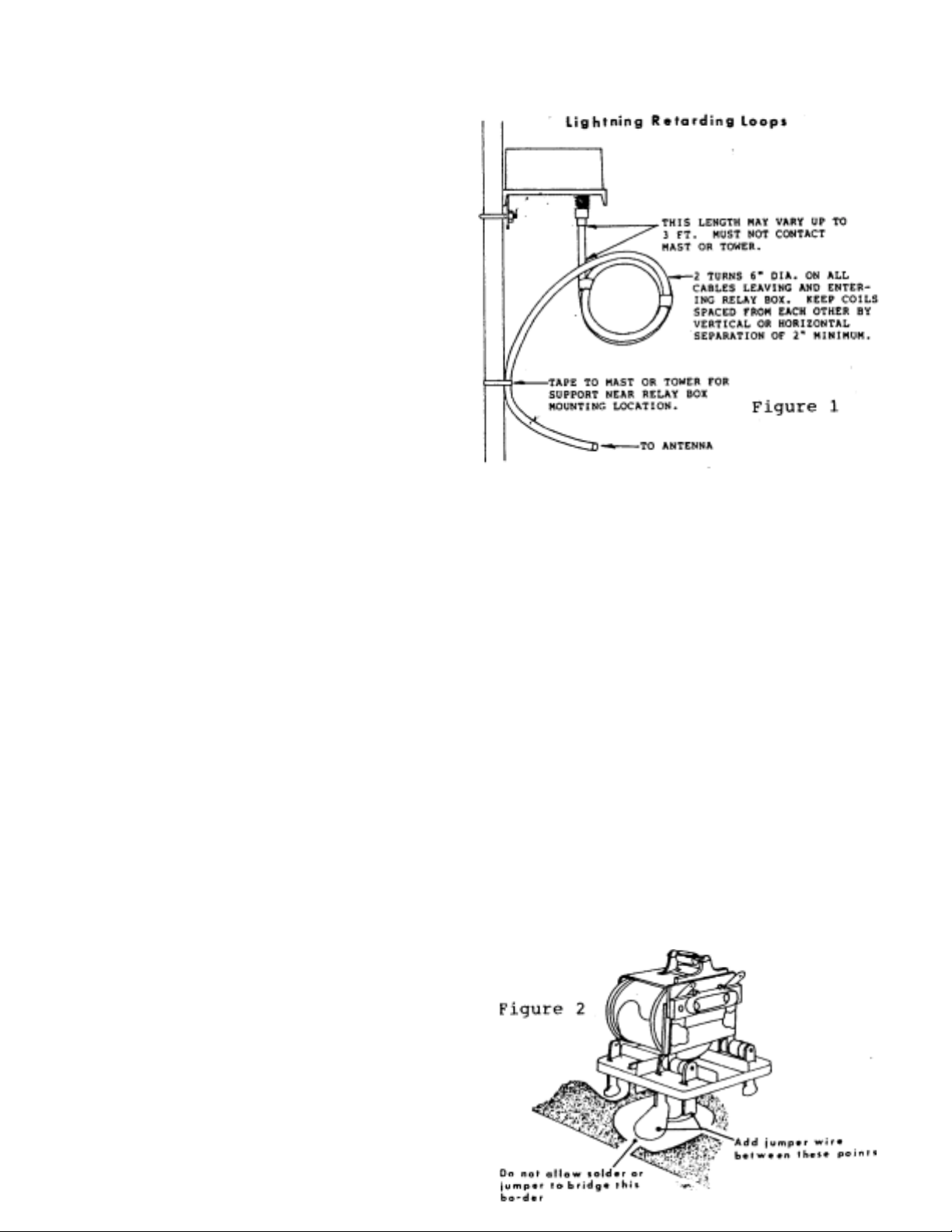
The relay box must be mounted with
the connectors down. Do not attempt
to air seal the relay box. Install
drip loops below the box if the
feedlines are brought in from a
higher location. Lightning retarding
loops are a recommended precaution
on all cables (see Figure 1.)
RELAY BOX CABLE RELAY BOX ANTENNA
inexpensive 5 or more conductor rotor
or telephone cable can be used to connect the relay box to the control console. The only requirement is that the
cable be physically able to survive
the environment it is installed in.
Wire gauge and voltage breakdown are
not critical. Conductor and ground
return (through the coax shield)
resistances can total 80 ohms before
operation becomes compromised.
Remove the four screws at the
corners of the panel and remove the
cover. Route one end of the control
cable. through the bushing in the
panel and through the plastic cable
clamp.
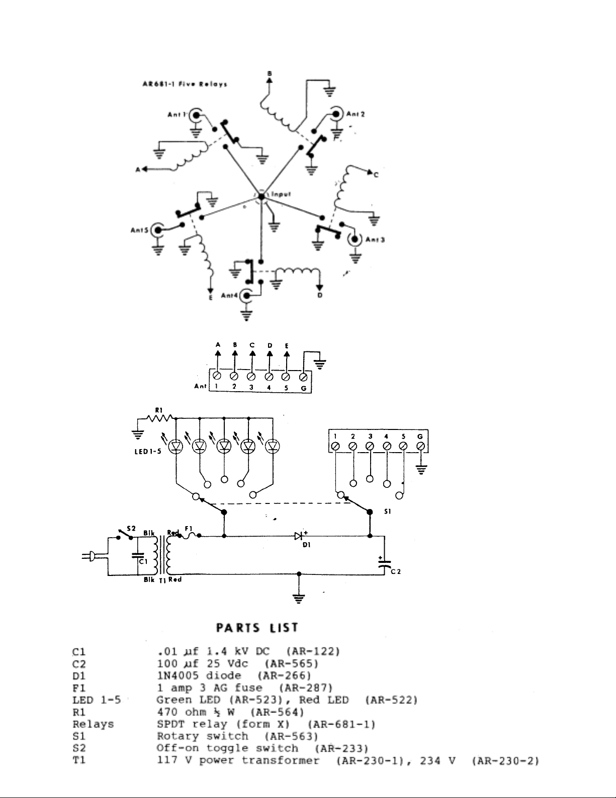
Connect 5 of the wires in the cable
to terminals 1 to 5. Make a note of
the color that is connected to each
terminal. If a sixth wire is
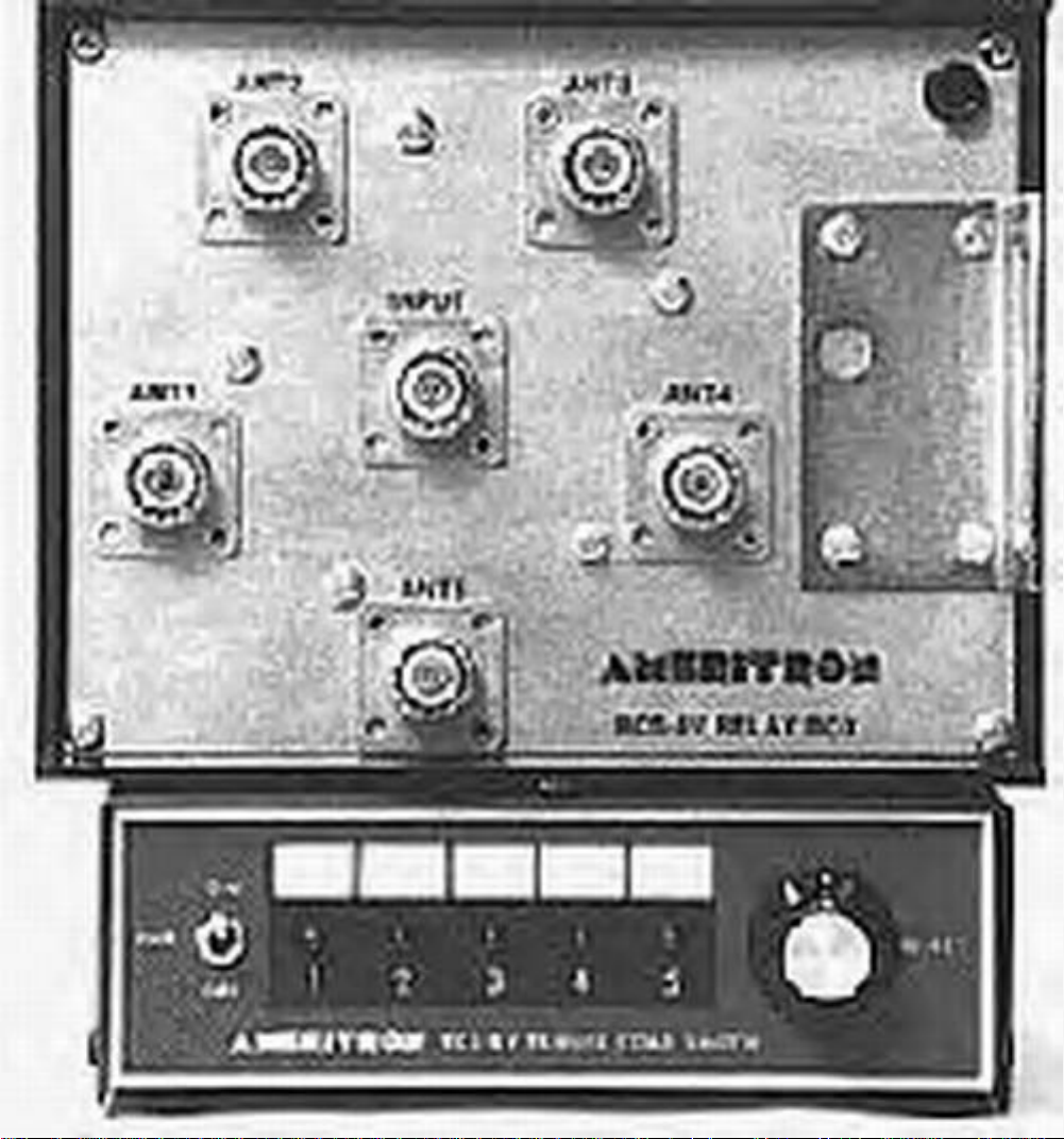
Connect your antennas to coax connectors numbered 1-5 and note which
antenna is connected to each
connector.
Connect the feedline to the
connector marked "INPUT."
If control power is removed the
relay box automatically disconnects
the "input" feed connection from all
antennaports.
Unselected antenna ports may be
automatically grounded or isolated.
The RCS-8V is shipped with the ports
isolated. To automatically ground
the unselected port a short jumper
must be installed as shown in Figure
2.
Re-install the cover on the panel
using the self tapping screws
previously removed.
Page 3

More than one antenna port can be
p
prop
g
g
"picked up"at one time by applying
control voltage to more than one
relay at one time. This allows the
user considerable flexibility in
stacking arrays of similar
antennas.
The "input" port
nection port. It can also be used as
an output.selecting up to five
inputs or left floating if-crossmatrix switching between the various
"Ant" ports is desired.
s the common con-
i
CONTROL CONSOLE CABLE
Locate the RCS-8V control console
at a convenient location on the
station o
The control console supplies 12 volt
DC control voltages. It has an
internal 1 amp fuse in the
transformer secondary circuit that
protects the power supply if a short
circuit occurs in the control cable.
eratingdesk.
OPERATION
1. Plug the line cord into the
er voltage outlet.
2. Place the PWR switch in the
"ON"position.
Connect the 5 wires in the cable to terminals 1 thru 5. Use the same color code
that was used on the relay box. If a
sixth wire is available in the con
trol cable, connect it to the "G"
terminal.
IMPORTANT: Connect the "G" terminal
to the station ground buss.
3. Rotate the SELECT control and
observe the li
The switch positions are numbered
on front of the control box and a
space is provided above each
position so you can pencil in a
desi
l. NEVER switch antennas with RF power
applied to the master feedline. Damage to
the switching contacts may result from
"hot switching".
nation for each antenna.
hts one thru
IMPORTANT
2. If one of the lights is dimmer than the rest it is
an indication of a short in the control cable
or between terminal screws.
Page 4
Downloaded by
Amateur Radio Directory
www.hamdirectory.info
Page 5
 Loading...