

American Water Heater 520 Installation Manual And Owner's Manual
520 Direct Vent Indoor and Outdoor Models
On-Demand Condensing Water Heater
Installation Manual and Owner’s Guide
FEATURING
ENDLESS HOT WATER
ON DEMAND USAGE
COMPACT, SPACE SAVING
ENERGY CONSERVATION
COMPUTERIZED SAFETY
NO PILOT LIGHT
EASY-LINK SYSTEM
WARNING
WARNING
If you have any questions, please
call or write to:
500 Tennessee Waltz Parkway
Ashland City, TN 37015
Toll Free: 1- 877-737-2840
This product must be installed and
serviced by a licensed plumber, a
licensed gas fitter, or a professional
service technician. Improper
installation and/or operation, or
installation by an unqualified
person, will void the warranty.
If the information in this manual is
not followed exactly, a fire or
explosion may result, causing
property damage, personal injury, or
death.
ANSI Z21.10.3 and CSA 4.3
Gas Tankless Wa
ter Heater
520 Direct Vent Indoor and
Outdoor Models
Su itab le for potable water he atin g an d space -he a ting
*
*Please refer to local codes for space-heating compliance.
Contents
2
│Page
CONTENTS
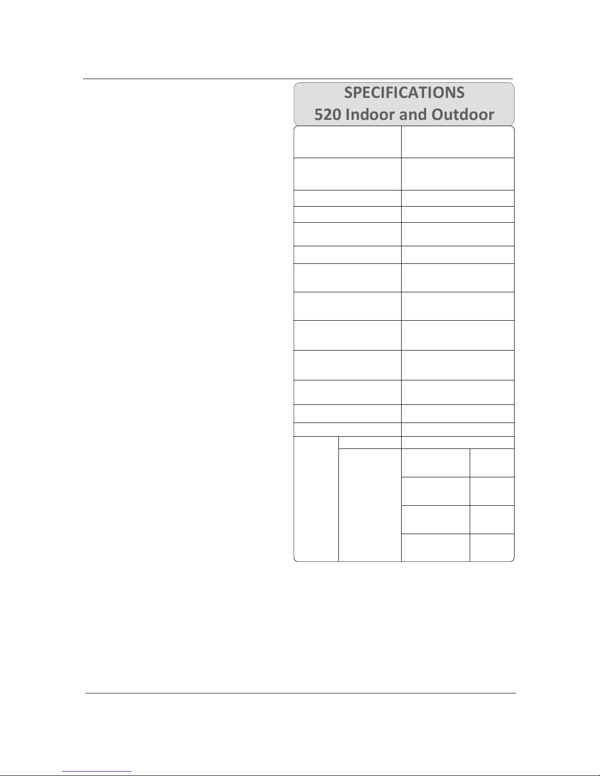
SPECIFICATION
S
520 Indoor and Outdoor
Natural Gas Input
(Operating Range)
Min: 13,000 Btu/h
Max: 199,000 Btu/h
Propane Input
(Operating Range)
Min: 13,000 Btu/h
Max: 199,000 Btu/h
Gas Connection ¾” NPT
Water Connections
¾” NPT
Condensate Drain Port
Connection
½” NPT
Water Pressure 15 - 150 psi*
Natural Gas
Inlet Pressure
Min. 5.0” WC
Max. 10.5” WC
Propane
Inlet Pressure
Min. 8.0” WC
Max. 14.0” WC
Manifold Pressure of
the 520 Indoor
Natural: 3.2” WC
Propane: 5.5” WC
Manifold Pressure of
the 520 Outdoor
Natural: 2.7” WC
Propane: 4.6” WC
Weight
73 lbs. (520 Indoor)
70 lbs. (520 Outdoor)
Dimensions
H25.6” x W18.5” x D12.4”
Ignition Electric Ignition
Supply 120 VAC / 60 Hz
Operation of the
520 Indoor
152 W
(1.27A)
Operation of the
520 Outdoor
102W
(0.85A)
Standby
8.2 W
(0.07A)
Electric
Consumption
FreezeProtection
207 W
(1.73A)
SPECIFICATIONS………………………………...
INTRODUCTION……………………………….…
SAFETY GUIDELINES…………….……………..
INSTALLATION………………………………..….
General………………………………………..…
Included Accessories…………………..…
Optional items…………………………..…..
Warning for Installations………..….....
High-altitude region support functions
…
520 Outdoor Installation……………..…
520 Indoor Installation….….………..…
Venting Instructions……………………..
..
Gas Supply / Gas Pipe Sizing………...
…
Water Connections……………..……….…
Pressure Relief Valve………………………
Condensate drain…………………………..
Electrical Connections……………........
.
Remote Controller Connection…….
…
Pump Control Connection………..…….
Pump Control Mode…………………….…
Easy-Link System…………………………....
APPLICATIONS...…………………………………
Space Heating……….………….……………
INITIAL OPERATION..…………………….……
OPERATING SAFETY……………………………
NORMAL OPERATION…………………………
General………..……….………….……………
Temperature settings.…….…..…………
Flow……………………………………………….
Freeze Protection System…….………
…
Maintenance and Service………………
Unit Draining and Filter Cleaning……
TROUBLESHOOTING……..……………………
General………..……….………….……………
Error codes.…………………….…..…………
COMPONENTS DIAGRAM………………..…
PARTS LIST………………….………………………
OUTPUT TEMPERATURE CHART……...…
LIMITED WARRANTY…………………….……
2
3
4
5
6
6
7
8
9
9
10
10
17
19
20
20
23
24
25
26
28
32
32
34
35
37
37
37
39
39
40
40
41
41
43
45
48
50
51
T
he
manufacturer
reserves
the right to
discontinue, or change at any time, specifications
or designs without notice and without incurring
obligations.
*40 psi or above is recommended for maximum flow
NOTE
*Check the rating plate to ensure this product
matches your specifications.
*In accordance with ANZI Z21.10.3, CO emission
does not exceed 400 PPM for normal input
Installation Manual
Owner
’
s Guide
Introduction
3│Page
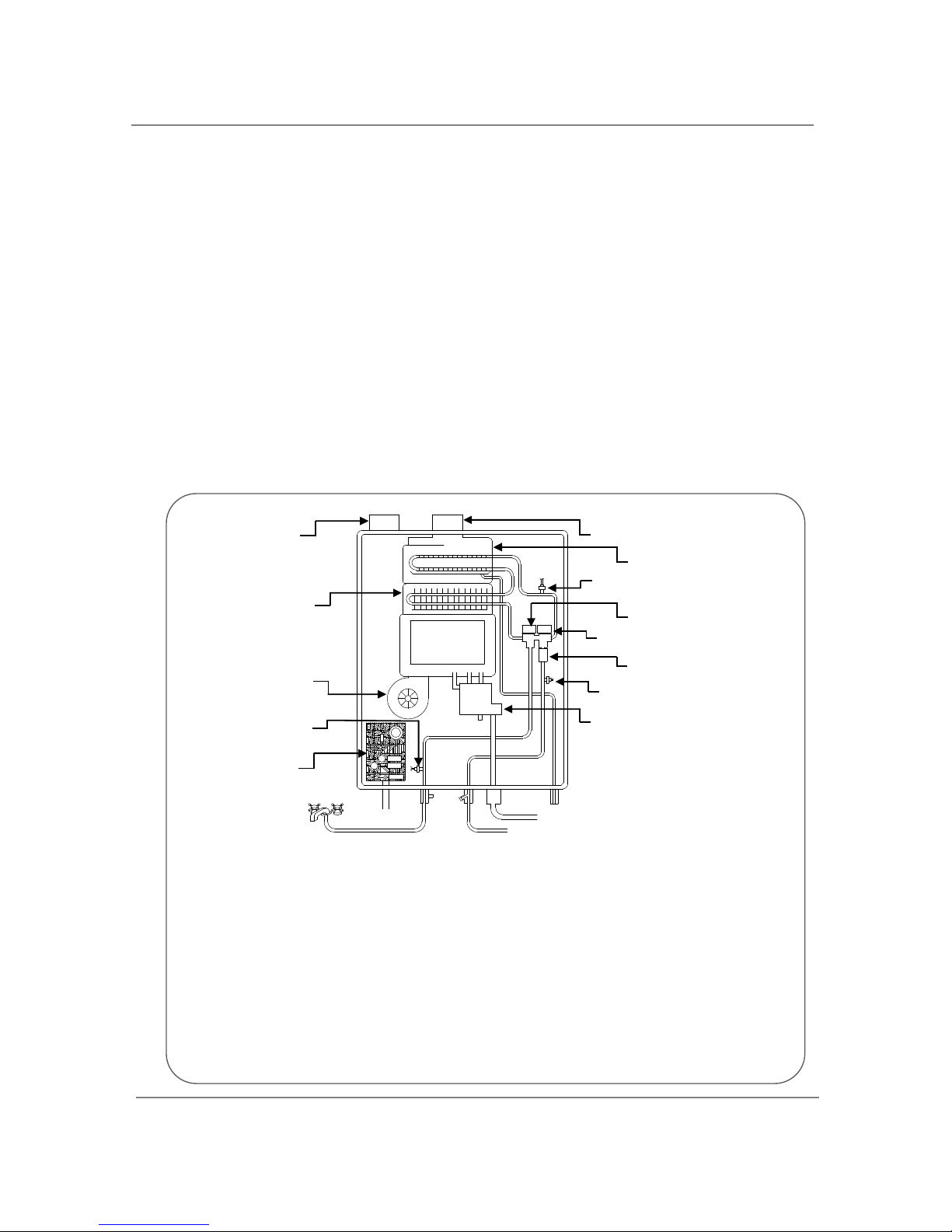
INTRODUCTION
*This diagram
illustrates tankless
water heater design
concepts only and
does not accurately
represent to the 520
Indoor and Outdoor
physical description.
This manual provides information necessary for the installation, operation, and
maintenance of the 520 Indoor and Outdoor.
The model description is listed on the rating plate which is attached to the side panel of
the water heater.
Please read all installation instructions completely before installing this product.
If you have any problems or questions regarding this equipment, consult with the
manufacturer or its local representative.
The 520 Indoor and Outdoor are on-demand, tankless water heaters designed to
efficiently supply endless hot water for your needs.
The principle behind the 520 Indoor and Outdoor Water Heater is simple:
1. A hot water tap is turned on.
2. Water enters the heater.
3. The water flow sensor detects the water flow.
4. The computer automatically ignites the burner.
5. Water circulates through the heat exchanger and then gets hot.
6. The computer will modulate the gas supply valve and water flow to produce the right
amount of hot water at the correct temperature.
7. When the tap is turned off, the unit shuts down.
The 520 Indoor and Outdoor are high efficiency models with an in-build secondary
heat exchanger that absorbs latent heat from the exhaust gas.
Burner
Condensate
drain port
Secondary heat exchanger
Thermistor
Thermistor
Gas Valve
Flow sensor
Water control valve
Bypass valve
Intake port
Exhaust
Fan motor
Primary heat
exchanger
Thermistor
PCB
Hot Water Outlet
Cold Water Outlet
Gas
Safety Guidelines
4│Page
Water temperatures over 125°F (52°C) can cause severe burns instantly or death from scalding.
The water temperature is set at 120°F (49°C) from the factory to minimize any scalding risk.
Before bathing or showering always check the water temperature.
Do not store or use gasoline or other flammables, vapors, or liquids in the vicinity
of this appliance.
Do not reverse the water and/or gas connections as this will damage the gas
valves and can cause severe injury or death. Follow the diagram on p. 19 when
installing your water heater:
Do not use this appliance if any part has been in contact with or been immersed in
water. Immediately call a licensed plumber, a licensed gas fitter, or a professional
service technician to inspect and/or service the unit if necessary.
Do not disconnect the electrical supply if the ambient temperature will drop
below freezing. The Freeze Prevention System only works if the unit has electrical
power. The warranty will not be covered if the heat exchanger is damaged due to
freezing. Refer to the section on the Freeze Prevention System on p. 39 for more
information.
SAFETY GUIDELINES
GENERAL
1. Follow all local codes, or in the absence of local codes, follow the most recent edition of the
National Fuel Gas Code: ANSI Z223.1/NFPA 54 in the USA or CAN/CSA B149.1 Natural Gas, Propane
Installation Code in Canada.
2. Properly ground the unit in accordance with all local codes or in the absence of local codes, with
the National Electrical Codes: ANSI/NFPA 70 in the USA or CSA standard C22.1 Canada Electrical
Code Part 1 in Canada.
3. Carefully plan where you intend to install your 520 Indoor and Outdoor Water Heater. Please
ensure:
Your water heater will have enough combustible air and proper
ventilation.
Locate your heater where water leakage will not damage
surrounding areas (please refer to p. 5).
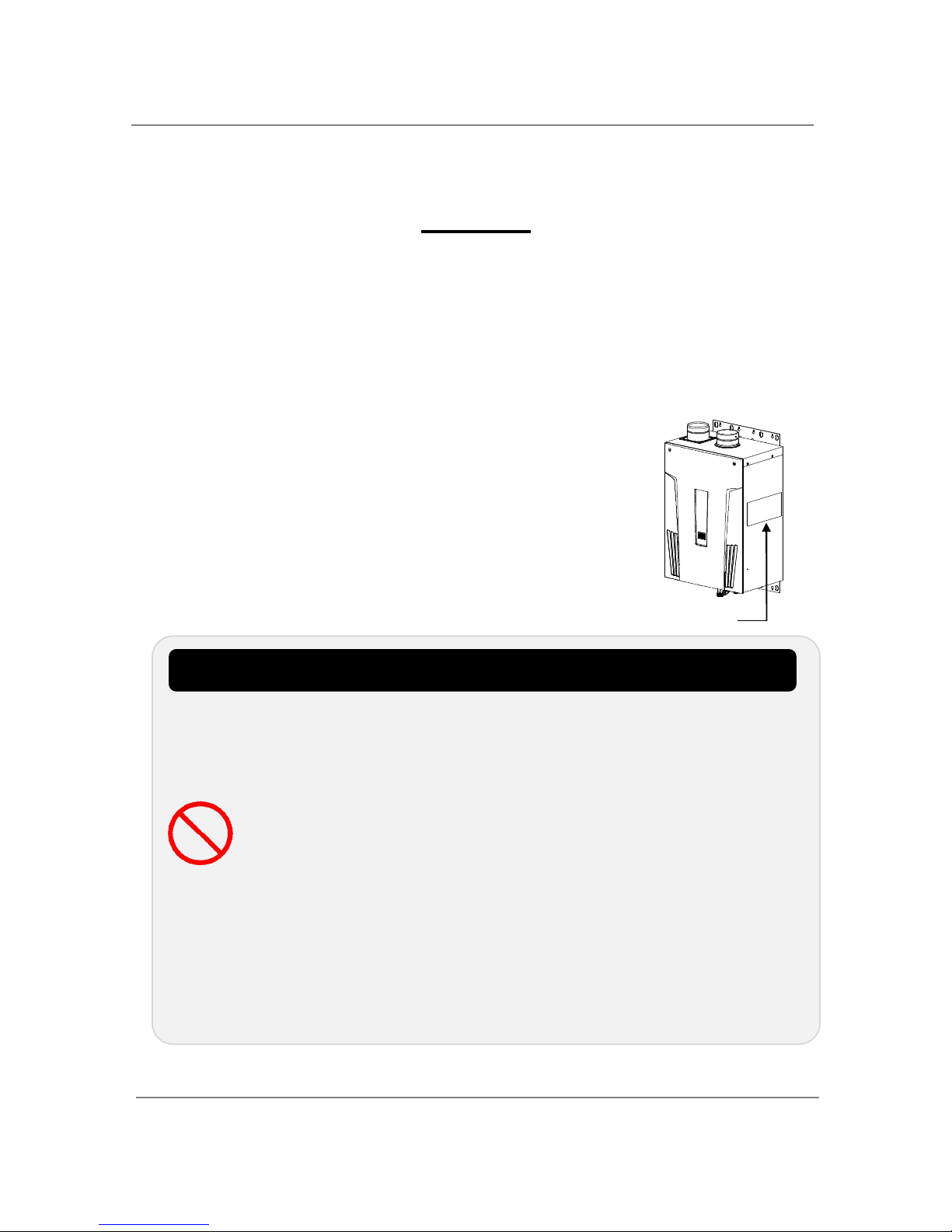
4. Check the rating plate for the correct GAS TYPE, GAS PRESSURE, WATER
PRESSURE and ELECTRIC RATING.
*If this unit does not match your requirements, do not install and
consult with the manufacturer.
5. If any problem should occur, turn off all hot water taps and turn off the
gas. Then call a trained technician or the Gas Company or the
manufacturer.
Prohibited
WARNING
RATING PLATE
Installation
5
│Page
Installation and service must be performed by a qualified installer (for
example, a licensed plumber or gas fitter), otherwise the warranty will be
void.
The installer (licensed professional) is responsible for the correct installation
of your 520 Indoor or Outdoor Water Heater and for compliance with all
national,
state/provincial
,
and local codes.
The warranty will not cover damage caused by water quality.
Only potable water or potable water / glycol mixtures can be used with this
water heater. Do not introduce pool or spa water, or any chemically
treated water into the water heater.
Water hardness levels must not exceed 7 grains per gallon (120 ppm) for
single family domestic applications or more than 4 grains per gallon (70
ppm) for all other types of applications. Water hardness leads to scale
formation and may affect/damage the water heater. Hard water scaling
must be avoided or controlled by proper water treatment.
Water pH levels must be between 6.5 and 8.5
Well water must be treated.
Although this water heater is designed to operate with minimal sound, the
manufacturer does not recommend installing the unit on a wall adjacent to a
bedroom, or a room that is intended for quiet study or meditation, etc.
Locate your heater close to a drain where water leakage will not do damage to
surrounding areas. As with any water heating appliance, the potential for
leakage at some time in the life of the product does exist. The manufacturer
will not be responsible for any water damage that may occur. If you install a
drain pan under the unit, ensure that it will not restrict the combustion air
flow.
The 520 models are high efficiency products that create condensation. A
condensation drain tube must be installed with these models to discharge
condensate into a drain outlet. For more information, refer to p. 20.
The manufacturer does not recommend installing the 520 Indoor models in
an attic due to safety issues. If you install your 520 Indoor models in an attic:
Make sure your unit will have enough combustion air and proper
ventilation.
Keep the area around you’re the water heater clean. When dust collects on
the flame sensor, the water heater will shut down on errors.
Locate unit for easy access for service and maintenance.
A drain pan, or other means of protection against water damage, is
required to be installed under the water heater in case of leaks.
INSTALLATION
All gas water heaters require careful and correct installation to ensure safe and efficient operation. This
manual must be followed exactly. Read the “Safety Guidelines” section at the beginning of this manual.
WARNING
WARNING
CAUTION
PLEASE READ THIS MANUAL CAREFULLY AND FOLLOW ALL DIRECTIONS.
Installation
6
│Page
GENERAL
1. Follow all local codes, or in the absence of local codes, follow the most recent edition of the
National Fuel Gas Code: ANSI Z223.1/NFPA 54 in the USA or CAN/CSA B149.1 Natural Gas,
Propane Installation Code in Canada.
2. The manifold gas pressure is preset at the factory. It is computer controlled and should not
need adjustment.
3. Maintain proper space for servicing. Install the unit so that it can be connected or removed
easily. Refer to p. 8, p.9 and p. 10 for proper clearances.
4. The electrical connection requires a means of disconnection, to terminate power to the water
heater for servicing and safety purposes.
5. If you will be installing the unit in a contaminated area with a high level of dust, sand, flour,
aerosols or other contaminants/chemicals, they can become airborne and enter and build up
within the fan and burner causing damage to the unit.
6. Particles from flour, aerosols, and other contaminants may clog the air vent or reduce the
functions of the rotating fan and cause improper burning of the gas. Regularly ensure that the
area around the unit is dust- or debris-free; regular maintenance is recommended for these
types of environment.
7. Do not install the unit where the exhaust vent is pointing into any opening in a building or where
the noise may disturb your neighbors. Make sure the vent termination meets the required
distance by local code from any doorway or opening to prevent exhaust from entering a building
(refer to p. 15).
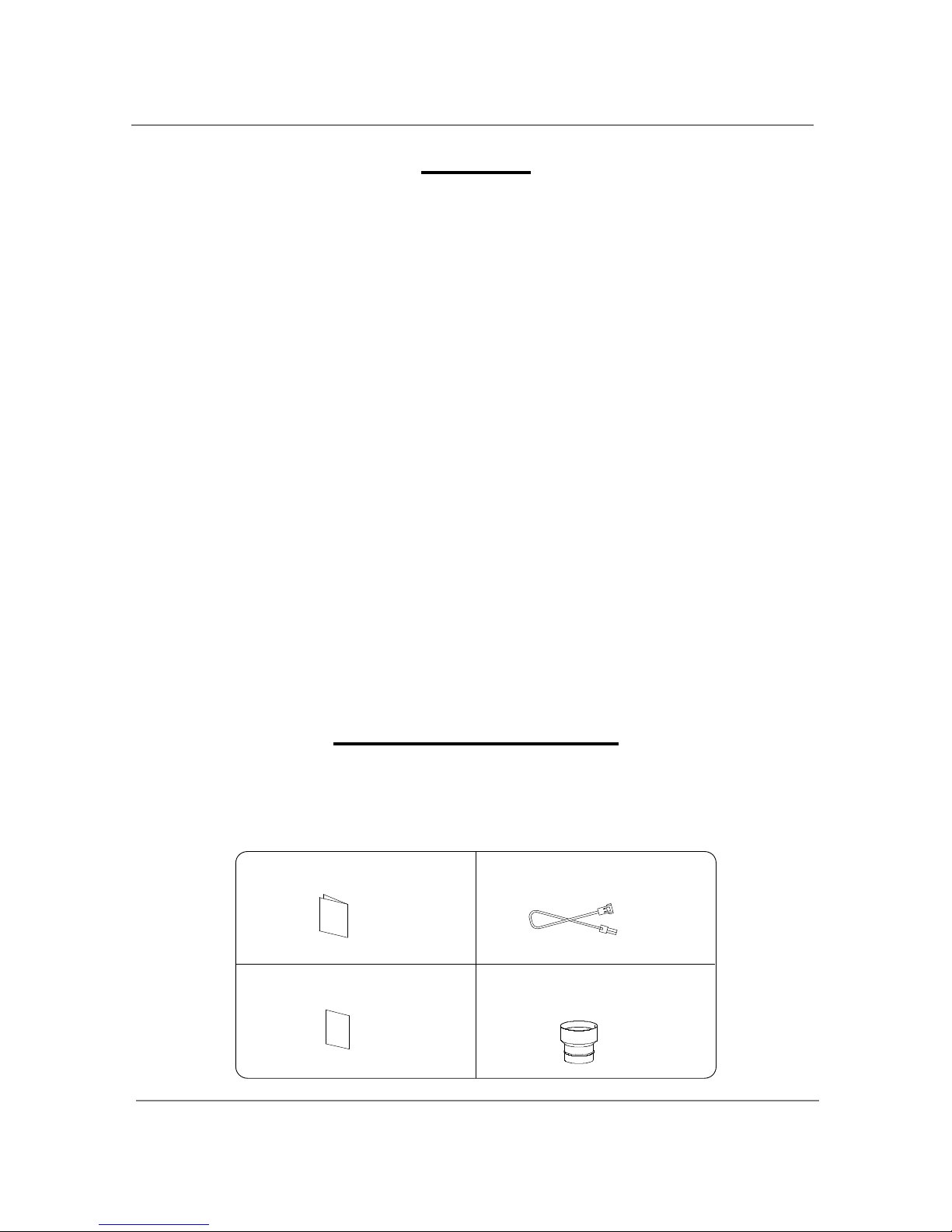
INCLUDED ACCESSORIES
Check that the installation manual, the communication cable, the product registration card and the PVC
adaptor are included with the unit (the adaptor comes with the 520 Indoor model only).
For details on how to connect the adaptor, refer to P.14.
1. Manual
2. Communication cable
3. Product Registration Card
4. PVC adaptor
(520 Indoor model only)
Qty: 1
Qty: 1
Qty: 1
Qty: 1
Installation
7
│Page
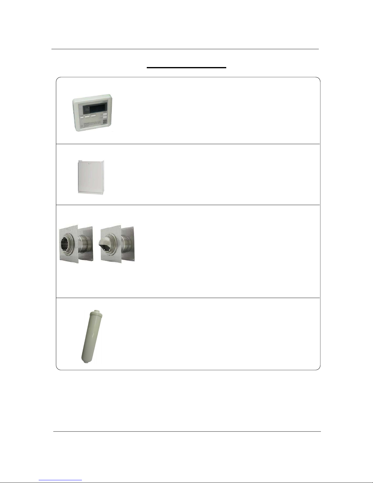
OPTIONAL ITEMS
1. Temperature Remote Controller: 9007603005
The Temperature Remote Controller has two functions. It allows
the output temperature from the 520 to be adjusted within the
range of 100 °F to 185 °F, and it also works as a diagnostic tool
that will give a concise error code whenever there is a problem
with the unit. The temperature options are 100°F, 105°F, 110°F,
115°F, 120°F, 125°F, 130°F, 135°F, 140°F, 145°F, 150°F, 155°F,
160°F, 165°F, 170°F, 175°F, 180°F and 185°F. See the trouble
shooting section for information on possible error codes.
2. Pipe cover: 9007606005
The Pipe cover protects the plumbing pipes to the 520 Indoor and
Outdoor models from unexpected adjustments. This pipe cover is
fixed to the bottom of the water heater, which hides the plumbing
and improves the visual aspects of the whole installation for the
water heater.
3. Wall thimble with Termination: 9007608005 and 9007609005
These terminations are used when venting out through the wall and
are compatible with the T-Vent pipe system.
These terminations are special stainless steel vents for gas appliances
and are UL listed as Category II, III and IV. There are two types of
terminations: the Louver termination and the Hood termination. For
different wall thicknesses, there are two ranges of lengths available
(refer to the venting brochure for details).
Install these vent terminations in accordance with their installation
instructions and any applicable local codes.
4. Neutralizer kit: 9007607005
The Neutralizer assembly neutralizes the condensate (acidic
water) that forms in the secondary heat exchanger of the 520
models.
It connects to the condensate drain port of the 520 models by
using connectors included with the neutralizer kit. Refer to p. 21
for the details.
Louver
Termination
9007608005
Hood
Termination
9007609005
Installation
8
│Page
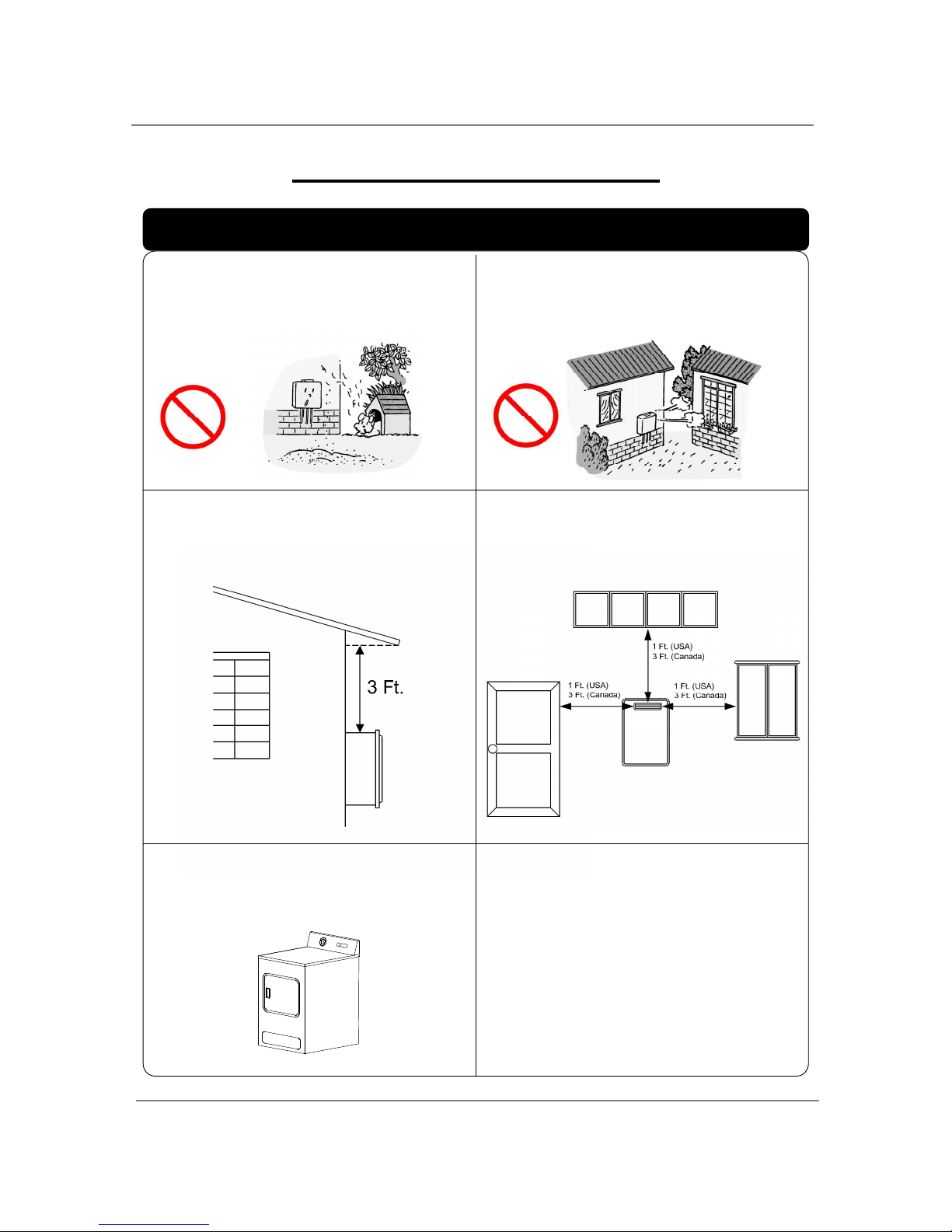
WARNING FOR INSTALLATIONS
FOR YOUR SAFETY, READ BEFORE INSTALLATION:
Do not install the heater where water, debris or
flammable vapors may get into the flue terminal.
This may cause damage to the heater and void
the warranty.
Do not have the vent terminal pointing toward
any opening into a building. Do not locate your
heater in a pit or location where gas and water
can accumulate.
Do not install this water heater under an
overhang less than 3 feet from its top or eaves.
The area under an overhang must be open to
three sides. (520 Outdoor only)
Do not install the water heater vent terminator
within 1 ft. in the USA of any air intake or building
opening, and with in 3 ft. in Canada of any air
intake or building opening. (520 Outdoor only)
(Refer to p.15)
Do not install next to a dryer or any source of
airborne debris that can be trapped inside the
combustion chamber, unless the system is direct
vented.
Prohibited
Prohibited
FOR YOUR SAFETY, READ BEFORE INSTALLATION:
Installation
9
│Page
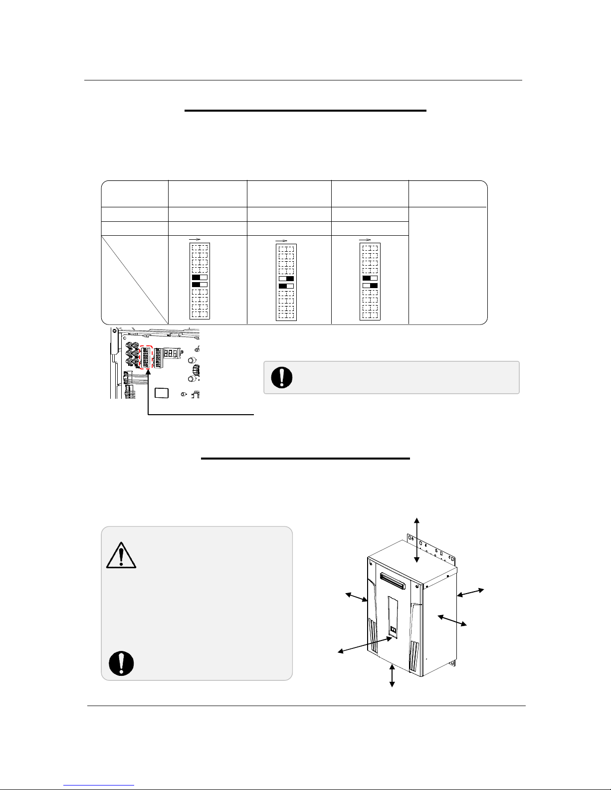
The dark squares indicate the direction the
dipswitches should be set to.
Left bank of dipswitches
Left ban
k of dipswitches
There is a 3” clearance from
the left and right sides of the
unit to combustible and noncombustible
surfaces. However, if any
portion or area of the surface
is exposed to the exhaust
fumes (i.e. directly to the sides
of the vent cap), that surface
must be at least 24” away.
Keep the clearances.
2,500 to 4
,000
ft
4,000 to 5
,000
ft
Altitude
HIGH-ALTITUDE INSTALLATIONS
Check the elevation where your water heater is installed. Set dipswitches shown in the table below
depending on the altitude. These dipswitches (No. 5 and No. 6) are on the computer board on the left
bank only.
0 to 2,500 ft
(DEFAULT)
Over 5,000 ft
Switch No.5
OFF
ON
OFF
Switch No.6
OFF OFF ON
Consult
our Technical
Services
Department
at 1-877737-2840
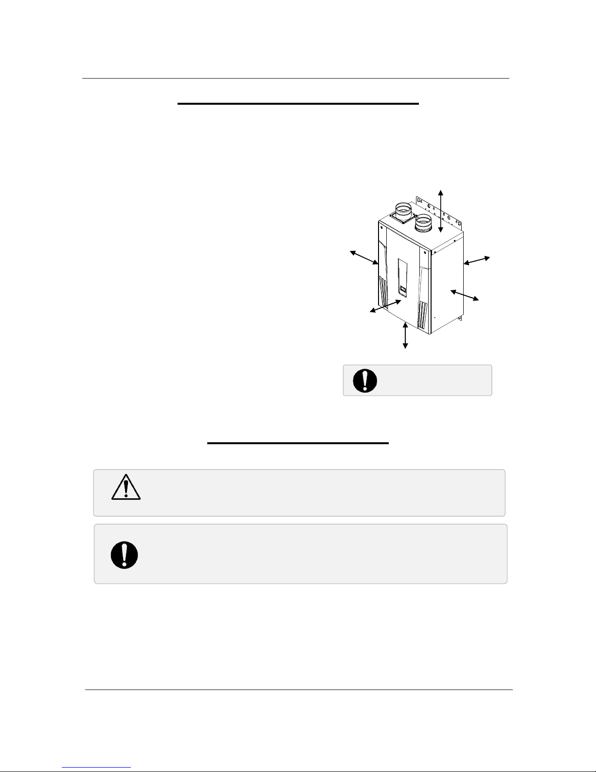
520 Outdoor INSTALLATION
1. Install the 520 Outdoor model only in areas with mild, temperate climates.
2. The 520 Outdoor model shall be wall-mounted or mounted on a stand. Locate the 520 Outdoor
model in an open, unroofed area and maintain the following minimum clearances:
DO NOT adjust
any
dipswitches
on
the right bank
.
1
2
3
4
5
6
7
8
N
O
9
1
0
N
O
1
2
3
4
5
6
7
8
9
1
0
N
O
1
2
3
4
5
6
7
8
9
1
0
Side 3”
Top 36”
Side 3” Front 24”
Bottom 12”
Back
0.5”
Installation
10
│Page
Improper venting of this appliance can result in excessive levels of carbon monoxide
which can result in severe personal injury or death.
When installing th
e vent system, all applicable national and local codes must be
followed. If you install thimbles, fire stops or other protective devices and they
penetrate any combustible or noncombustible construction, be sure to follow all
applicable national and local codes.
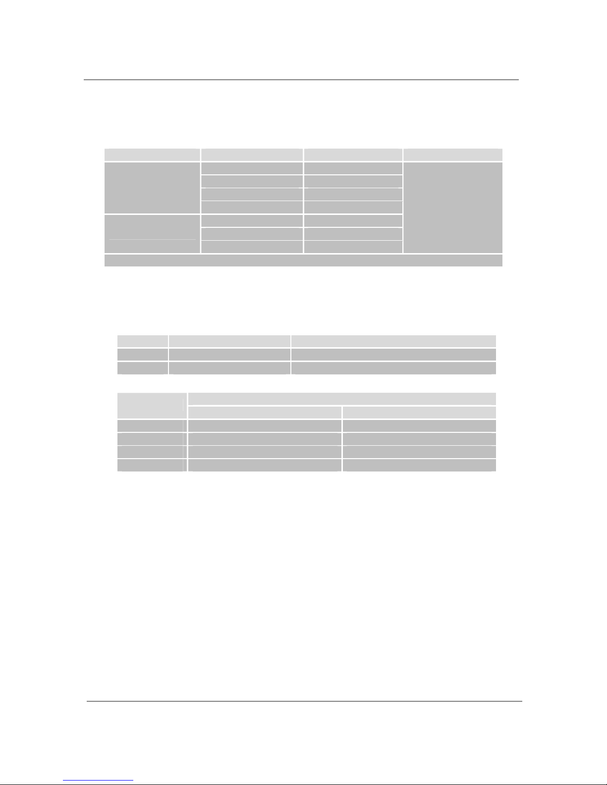
520 Indoor model INSTALLATION
The 520 Indoor models are equipped with a thermistor and hi-limit switch for the exhaust gas, detecting
excess temperatures within the flue and enabling the unit to safely stop operations if needed. These
components are always monitoring exhaust gas conditions in order to prevent heat damage to PVC
(Plastic) venting if PVC is used.
If the exhaust gas temperature exceeds 140°F, these components will enable the unit to safely stop
operations. (For the 520 Outdoor model, these components are not available since there’s no exhaust
venting required.)
520 Indoor model requires a 4” make-up intake air
supply pipe. The intake pipe must be sealed airtight.
Air supply pipe can be made of ABS, PVC,
galvanized steel, corrugated stainless steel,
or Category lll / IV stainless steel.
Sidewall venting is recommended for the
520 Indoor models. Vertical venting (roof
termination) is acceptable.
The manufacturer recommends
running the exhaust vent and the
intake pipe as parallel as possible.
The PVC adaptor is used to make the
connection between the 520 Indoor
vent collar and PVC vent pipe easier
and for maintenance purposes.
VENTING INSTRUCTIONS
-General-
The 520 Indoor models must be vented in accordance with the section “Venting of Equipment" of the
latest edition of the National Fuel Gas Code: ANSI Z223.1/NFPA 54 in the United States and/or Section 7
of the CAN/CSA B149.1 Natural Gas and Propane Installation Code in Canada, as well as applicable local
building codes.
The use of venting materials approved for Category III/IV appliances is recommended whenever possible.
However, 520 Indoor may also be vented with plastic pipe materials such as PVC. For details, please
refer to the Exhaust Vent (PVC Vent) section on p. 11. Vent installations in Canada which utilize plastic
vent systems must use venting that complies with ULC S636.
WARNING
Top 12” Side 3”
Back
0.5”
Side 3”
Front
4”
(24” Recommended
for Maintenance)
Bottom 12”
Keep the clearances.
Installation
11
│Page
Excludes elbow termination, rain caps, or the
3”
PVC Concentric Termination
For details on th
e vent connectio
n to the 520 Indoor, refer
to P.14
* For each elbow add
ed, deduct 5 ft. from max. v
ent length.
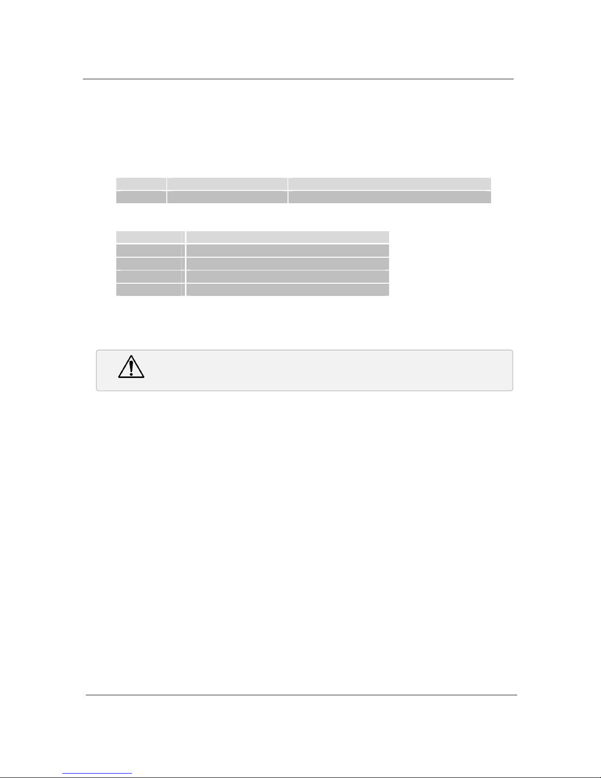
-Exhaust vent (PVC & ABS vent) -
The 520 Indoor models can be connected with PVC or ABS venting (temperature rated up to 149°F).
However, the manufacturer recommends PVC (or ABS) venting certified to ULC S636 standards.
Item Material United States Canada
Schedule 40 PVC ANSI/ASTM D1785
PVC-DWV ANSI/ASTM D2665
Schedule 40 CPVC ANSI/ASTM F441
Exhaust pipe &
Fittings
Schedule 40 ABS-DWV ANSI/ASTM D2661
PVC ANSI/ASTM D2564
CPVC ANSI/ASTM F493
Pipe Cement/Primer
ABS ANSI/ASTM D2235
ULC S636 Certified
Materials Only
NOTE: Do NOT Use Cellular Foam Core Pipe
The maximum length of exhaust vent piping must not exceed 50 ft. for 4” venting and 25 ft. for
3” venting (deducting 5 ft. for each elbow used in the venting system). Do not use more than 5
elbows for 4” venting and 2 elbows for 3” venting.
When the horizontal vent run exceeds 5 ft., support the vent run at 3 ft. intervals with overhead
hangers.
Diameter
Max. No. of Elbow Max. Vertical & Horizontal (Total) Vent Length
3” 2 25 ft.
4” 5 50 ft.
Max. Vertical or Horizontal Length
No. of Elbows
3” venting 4” venting
0 25 ft. 50 ft.
1 20 ft. 45 ft.
2 15 ft. 40 ft.
5 N/A 25 ft.
This is a Category IV appliance and must be vented accordingly. The vent system must be sealed air tight.
All seams and joints without gaskets must be sealed with high heat resistant silicone sealant or UL listed
aluminum adhesive tape having a minimum temperature rating of 160°F. For best results, a vent system
should be as short and straight as possible.
The 520 Indoor is a Category IV appliance and must be vented accordingly with any 4” vent
approved for use with Category III/IV or Special BH type gas vent.
The manufacturer recommends the “T-Vent” line manufactured by TAKAGI (Refer to Takagi’s
“T-Vent” brochure for details). However, the following are also UL listed manufacturers: ProTech
Systems Inc. (FasNSeal), Flex-L Inc., Z-Flex Inc. (Z-Vent III), Metal-Fab Inc., and Heat-Fab Inc. (SafT Vent).
-
Exhaust vent (Stainless steel vent)
-
Installation
12
│Page
Improper installation can cause nausea or asphyxiation
, severe injury or death
from
carbon monoxide and flue gases poisoning. Improper installation will void product
warranty.
Follow the vent pipe manufacturer’s instructions when installing the vent pipe.
Do not common vent this appliance with any other vented appliance (Do not terminate vent
into a chimney. If the vent must go through the chimney, the vent must run all the way through
the chimney with Category III / IV approved or Special BH vent pipe).
The maximum length of exhaust vent piping must not exceed 50 ft. (deducting 5 ft. for each
elbow used in the venting system). Do not use more than 5 elbows.
When the horizontal vent run exceeds 5 ft., support the vent run at 3 ft. intervals with overhead
hangars.
Diameter
Max. No. of Elbow Max. Vertical & Horizontal (Total) Vent Length
4” 5 50 ft.
*For each elbow added, deduct 5 ft. from max. Vent length.
No. of Elbows
Max. Vertical or Horizontal Length
0 50 ft.
1 45 ft.
2 40 ft.
5 25 ft.
-Vent termination -
The vent terminator provides a means of installing vent pipe through the building wall and must be
located in accordance with ANSI Z223.1/NFPA 54, or in Canada with CAN/CSA-B149.1 and local
applicable codes.
A proper sidewall direct-vent terminator is recommended when the water heater is vented through a
sidewall.
General rules for venting the 520 Indoor water heater are:
1. Place the water heater as close as possible to the vent terminator.
2. The vent collar of the water heater must be fastened directly to an unobstructed vent pipe or PVC
adaptor.
3. Do not weld the vent pipe to the water heater collar.
4. Do not cut the vent collar of the unit.
5. The weight of the vent stack must not rest on the water heater.
6. The vent must be easily removable from the top of the water heater for normal service and
inspection of the unit.
7. The water heater vent must not be connected to any other gas appliance or vent stack.
8. Avoid locating the water heater vent terminator near any air intake devices. These fans can pick
up the exhaust flue products from the water heater and return them to the building. This can
create a health hazard.
9. Avoid using an oversized vent pipe or using extremely long runs of the pipe.
10. Locate the vent terminator so that it cannot be blocked by any debris, at any time. Most codes
require that the terminator be at least 12 inches above grade, but the installer may determine if it
should be higher depending on the job site condition and applicable codes.
11. For rooftop venting, a rain cap or other form of termination that prevents rain water from entering
into the water heater must be installed.
WARNING
Installation
13
│Page
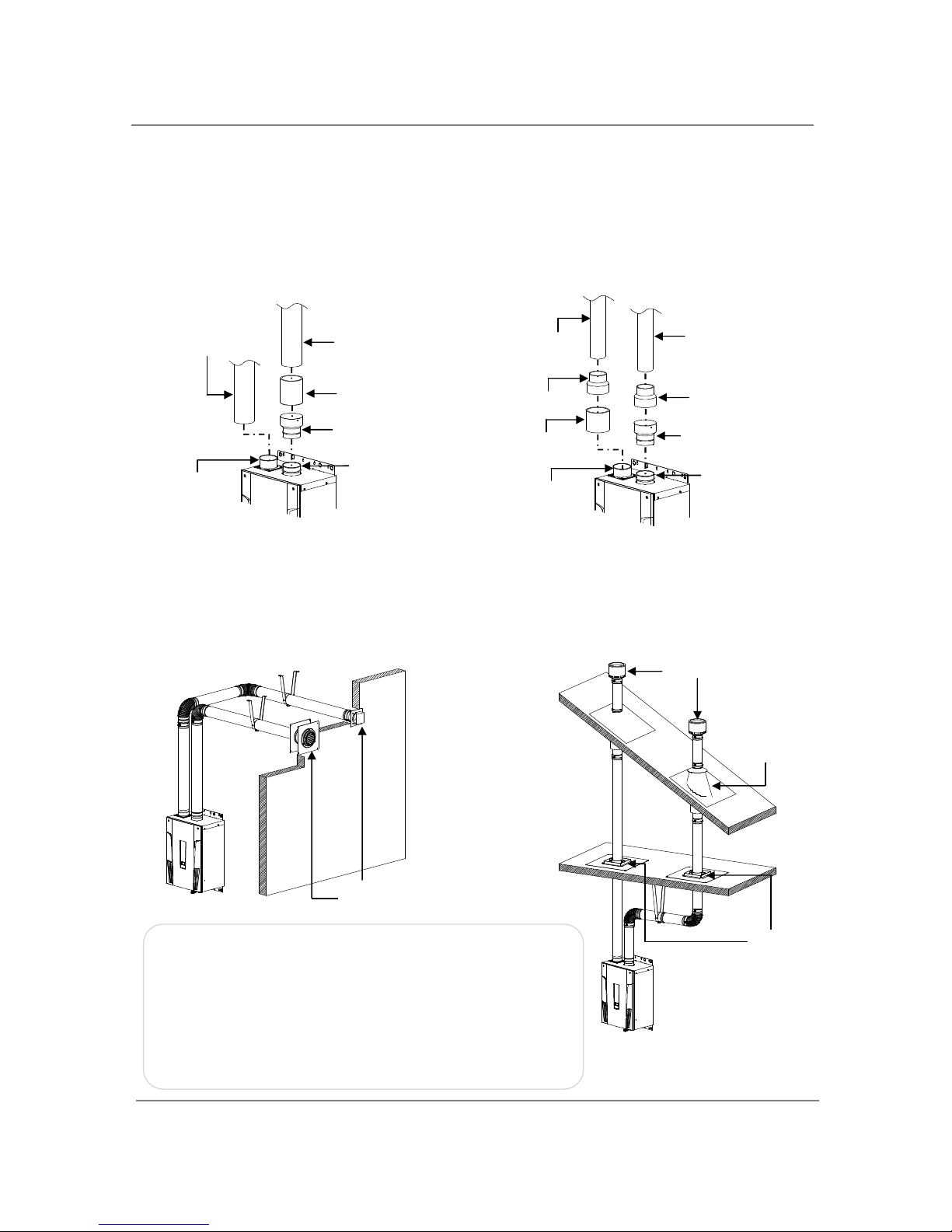
1. Conn
ect the
PVC adaptor* directly on the exhaust vent collar of the
water heater
.
2. Connect a 4” PVC coupler (or 4x3” PVC reducer) to the PVC adaptor.
3. From the coupler (or reducer), continue on the rest of the vent run with 4” PVC pipe (or 3” PVC
pipe.)
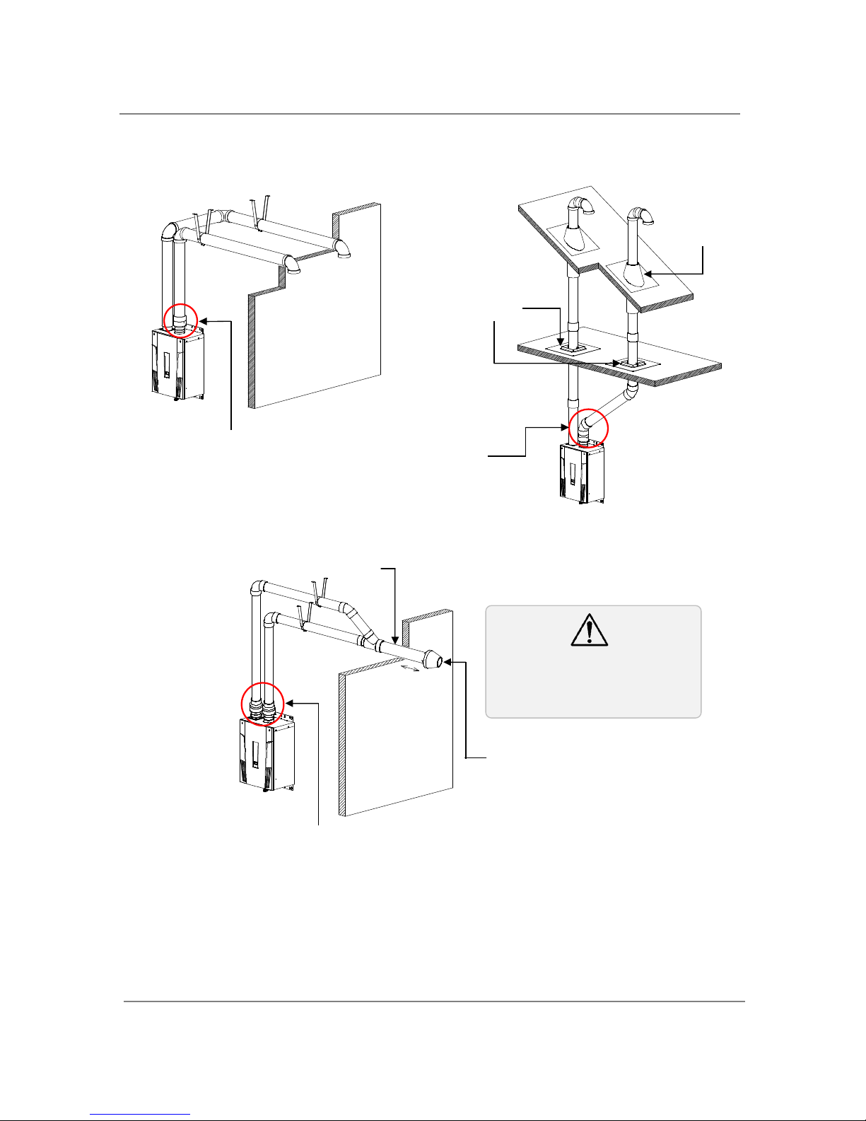
(For Exhaust)
Horizontal Instal
lation Diagram
(With elbow terminations)
Horizontal Installation Diagram
(With 3” PVC Concentric Termination)
Keep
a
1” clearance between wall
and the intake section of the
concentric termination. See the
diagram to the left.
-
PVC Venting Illustrations
-
How to install PVC venting with the 520 Indoor
Connection between exhaust vent collar and PVC piping
See the next page for instructions.
Wall
Connection between exhaust vent collar
and PVC piping
See the next page for instructions.
Wall
1” minimum
clearance
Concentric
T
ermination
Insert the bird screen included with
the termination
Vertical Installation Diagram
Roof Roof Flashing
Fire stop
Installation
14
│Page
1. Connect
a 4”
PVC Straight pipe directly on the intake vent collar of the
water heater
.
2. Connect a 4x3” PVC reducer to the 4” PVC Straight pipe.
3. From the reducer, continue on the rest of the vent run with 3” PVC pipe.
(For
Intake: 4
”
only)
(For
Intake: 3
”
only)
Regarding the clearances from the exhaust terminator to the
air inlet or opening, refer to the next few pages.
Follow all vent system manufacturer’s instructions and all
local codes.
Do not common vent or connect any vent from other
appliances to the 520 Indoor water heater vent.
Use 4” Category III/IV approved or Special BH, single or
double wall stainless steel vent pipe.
Vertical Installation Diagram
Horizontal Installation Diagram
*PVC adaptor is included with the 520 Indoor.
4” vent connection Diagram
3” vent connection Diagram
-Stainless steel Venting Illustrations-
1. C
onnect a 4
”
PVC Straight pipe directly on the i
ntak
e vent collar of the water heater.
3” PVC Straight pipe
4x3” PVC reducer
PVC adaptor*
Exhaust vent collar of
the 520 Indoor (Female)
3” PVC Straight
pipe
4x3” PVC reducer
4” PVC Straight
pipe
Intake
vent collar
Roof Flashing
Roof
Rain Cap
Fire stop
Wall
Sidewall Vent
Terminator
Exhaust vent collar of
the 520 Indoor (Female)
PVC adaptor*
4” PVC coupler
4”
PVC Straight pipe
4”
PVC Straight
pipe
Intake vent collar
Installation
15
│Page
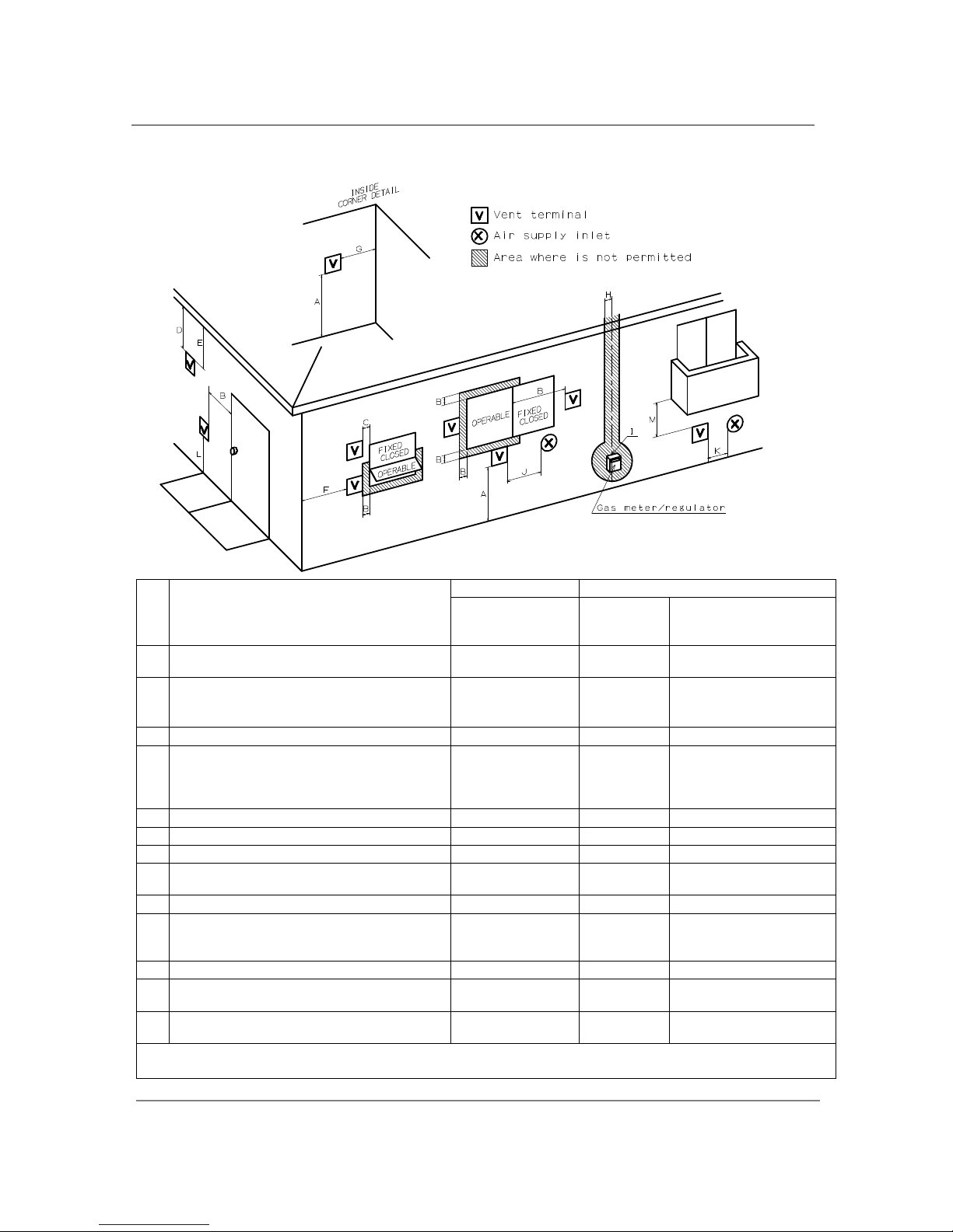
-Vent clearances-
Canada U.S.A
Direct vent and
other than Direct
Vent
Direct vent Other than Direct Vent
A
Clearance above grade, veranda, porch, deck,
or balcony.
1 foot 1 foot 1 foot
B
Clearance to window or door that may be
opened.
3 feet 1 foot
4 feet from below or side
opening. 1 foot from
above opening.
C
Clearance to permanently closed window * * *
D
Vertical clearance to ventilated soffit located
above the vent terminator within a horizontal
distance of 2 feet (61cm) from the center line
of the terminator.
* * *
E
Clearance to unventilated soffit * * *
F Clearance to outside corner * * *
G
Clearance to inside corner * * *
H
Clearance to each side of center line extended
above meter/regulator assembly
3 feet * *
I
Clearance to service regulator vent outlet. 3 feet * *
J
Clearance to non-mechanical air supply inlet
to building or the combustion air inlet to any
other application.
3 feet 1 foot
4 feet from below or side
opening. 1 foot from
above opening.
K
Clearance to mechanical air supply inlet. 6 feet 3 feet 3 feet
L
Clearance above paved sidewalk or paved
driveway located on public property.
7 feet * 7 feet
M
Clearance under veranda, porch deck, or
balcony.
1 foot * *
*For clearances not specified in ANSI Z223.1 / NFPA 54 or CAN/CSA-B149.1, please use clearances in accordance with
local installation codes and the requirement of the gas supplier.
Installation
16
│Page
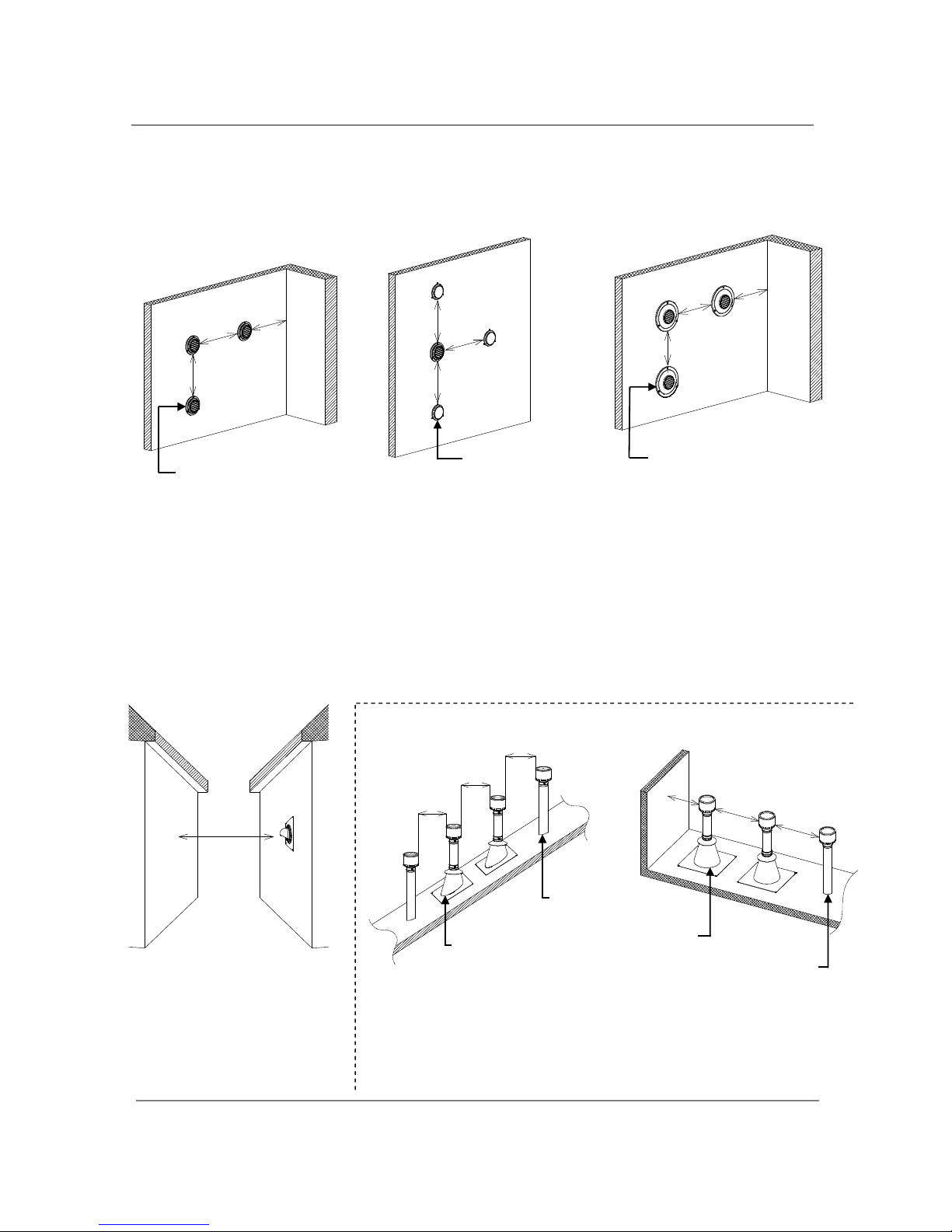
-Additional clearances -
Please follow all local and national codes in regards to proper termination clearances. In the absence of
such codes, the following clearances can be used as guidelines. Local codes supersede these guidelines.
For sidewall terminations
Exhaust termination
1ft.
1ft.
2ft.
Inside
corner
For multiple sidewall exhaust
terminations (e.g. multi-unit
systems), an exhaust termination
must be at least 1 ft. away from
another exhaust termination. An
exhaust termination must also be
at least 2 ft. away from an inside
corner (if the adjacent wall is less
than 2 ft. of length, the minimum
required distance away from the
inside corner will be equal to the
length of that adjacent wall).
For direct
-
vent sidewall
terminations that use two
separate penetrations for the
intake and exhaust, distance
the intake and exhaust
terminations at least 3 ft. away
from each other, no matter the
orientation.
For multiple
-
unit, direct
-
vent sidewall
terminations that combine the intake
and exhaust into a single penetration,
space each direct-vent termination at
least 1 ft. away from each other, no
matter the orientation. A direct-vent
termination must also be at least 2 ft.
away from an inside corner (if the
adjacent wall is less than 2 ft. of
length, the minimum required
distance away from the inside corner
will be equal to the length of that
adjacent wall).
For multiple
-
unit rooftop terminations (whether
for standard indoor or
direct-vent installations) space all exhaust and intake terminations in
accordance with local codes. An exhaust termination must be spaced from
a wall or surface in accordance with local codes as well. In the absence of
such a code, an exhaust termination must be a horizontal distance of at
least 2 ft. away from a wall or surface.
A: in accordance with local codes
For rooftop terminations
Air intake
Exhaust
termination
A A
A
A
A
2ft.
Air intake
Exhaust
termination
Exhaust and/or direct
-
vent
sidewall terminations should
be at least 2 ft. away from an
opposite surface/wall. Do
not place the termination
directly in front of an
opening into a building.
2ft.
Exhaust
termination
Air supply inlet
3ft.
3ft.
3ft.
Direct vent terminat
ion
1ft.
1ft.
Inside
corner
2ft.
 Loading...