

Page 1

Installation and Operation Manual
®
AllSync Plus® Clocks
Part # P000018
Rev. 3
January 2013
Page 2

AllSync Plus Clock Installation
& Operation Manual
American Time
140 3rd Street South, PO Box 707
Dassel, MN 55325-0707
Phone: 800-328-8996
Fax: 800-789-1882
american-time.com
2
© American Time
Page 3

AllSync Plus Clock Installation
& Operation Manual
Table of Contents
Safety Precautions ........................................................................................................................................................ 4
Introduction 5
Installation ..................................................................................................................................................................... 6
Electrical Connections ............................................................................................................................................. 6
Plastic Surface Mount Clock Installation .................................................................................................................. 7
Metal Surface Mount Clock Installation ................................................................................................................... 9
Metal Round Double Dial Clock Installation ........................................................................................................... 10
Plastic Double Dial Clock Installation ..................................................................................................................... 12
Metal Square Double Dial Clock Installation .......................................................................................................... 13
AllSync Plus Startup Routine ................................................................................................................................. 14
General Operation ........................................................................................................................................................ 16
AllSync Plus accuracy ........................................................................................................................................... 16
Movement corrections .......................................................................................................................................... 16
Start Up Example Operation .................................................................................................................................. 17
Troubleshooting ........................................................................................................................................................... 18
Appendix A - AllSync Plus Clock Specifications ....................................................................................................... 20
AllSync Plus Flush Metal Case Specifications ........................................................................................................ 20
AllSync Plus Flush Plastic Case Specifications ...................................................................................................... 22
AllSync Plus Dual Motor Metal Case Specifications ............................................................................................... 24
AllSync Plus Dual Motor Plastic Case Specifications .............................................................................................. 26
AllSync Plus Surface & Double Dial Metal Case Specifications .............................................................................. 28
AllSync Plus Surface & Double Dial Plastic Case Specifications ............................................................................. 30
Appendix B - LED Indication ....................................................................................................................................... 32
Glossary ....................................................................................................................................................................... 34
© American Time
3
Page 4

Safety Instructions
All wiring to AllSync Plus clock(s) and Master must be installed by qualified persons in conformance with
applicable national and local electrical codes. Improper installation of this equipment can result in lethal electrical
shock and fire.
Disconnect and lock out electrical power to AC clocks before wiring.
There are no user serviceable parts inside AllSync Plus clocks.
The AllSync Plus clock(s) should be installed in a location protected from:
• Water, including condensation
• Physical damage
Installation Introduction
AllSync Plus Clock Installation
& Operation Manual
Operation
Troubleshooting General
Appendix A
Specications
Illumination
Glossary Appendix B LED
4
© American Time
Page 5

AllSync Plus Clock Installation
& Operation Manual
Introduction
The AllSync Plus Clock Manual explains how to install AllSync Plus Clocks and understand their operation.
The American Time AllSync Plus clock is the second generation of the AllSync Chameleon clock. The AllSync Plus
clock incorporates all of the first generation AllSync clock features with improved accuracy and 15 minutes of
reserve power for short power outages.
InstallationIntroduction
Operation
TroubleshootingGeneral
Specications
Appendix A
Illumination
© American Time
GlossaryAppendix B LED
5
Page 6
Installation
Electrical Connections
Warning:
To prevent electrical shock, do not apply electrical power to master, clock relays and clock wiring before
completing all wiring connections.
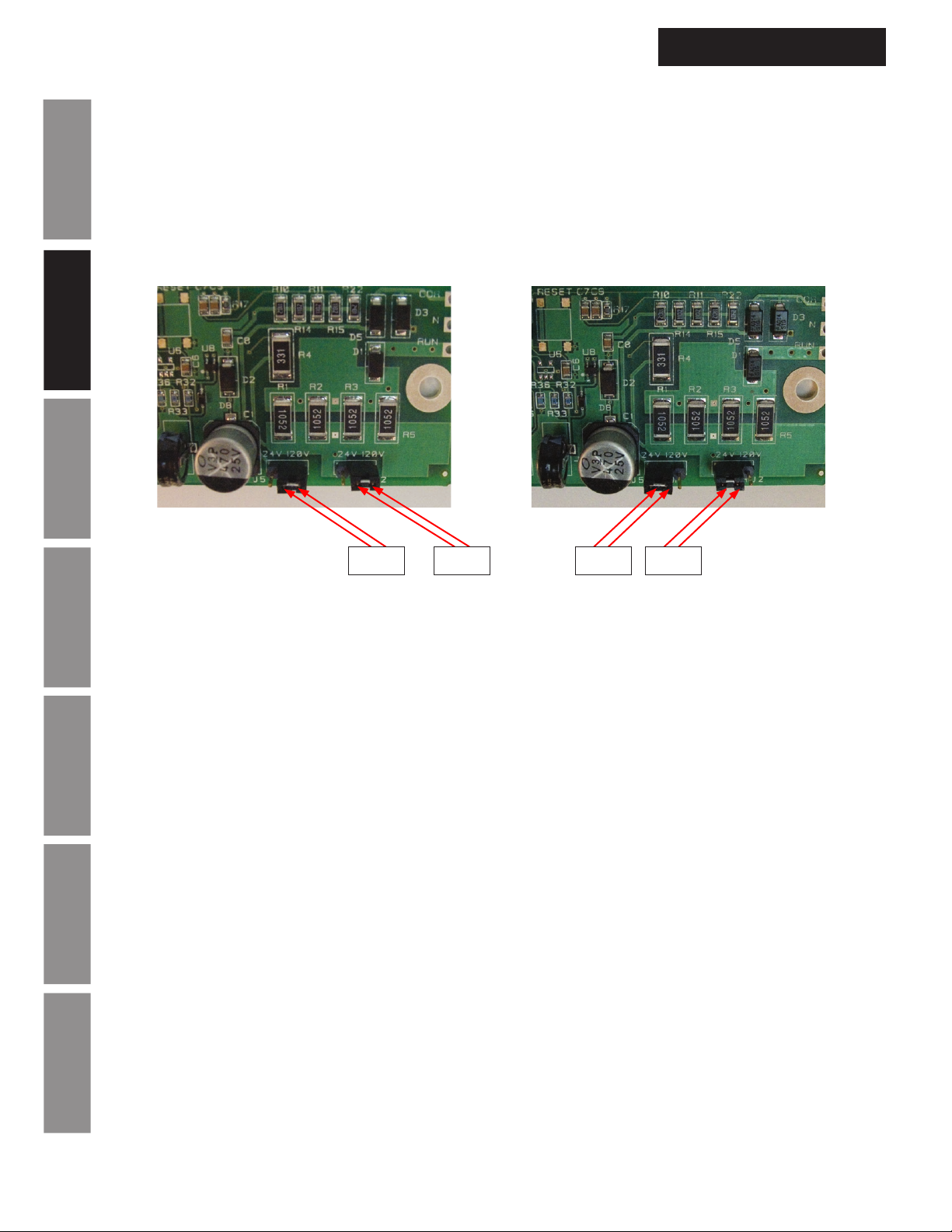
The AllSync Plus clock can run off either 24vac/60 Hz or 120vac/60 Hz. To change between the two different
supply voltages two jumpers must be set inside each clock. This setting is completed by American Time when
your clock(s) are built according to the part number ordered.
Installation Introduction
AllSync Plus Clock Installation
& Operation Manual
Operation
Correction
Run
Correction
120V 120V
24V 24V
Run
Caution:
Setting the AllSync Plus clock for 24vac and powering it with 120vac will damage the circuit board.
Red wire = Correction
Black wire = Run
Troubleshooting General
White wire = Neutral
Green wire = Ground
Appendix A
Specications
Illumination
Glossary Appendix B LED
6
© American Time
Page 7
AllSync Plus Clock Installation
& Operation Manual
Installation
Plastic Surface Mount Clock Installation
Warning:
The AllSync Plus plastic surface mount clock should be mounted according to these instructions to meet
UL clock listing.
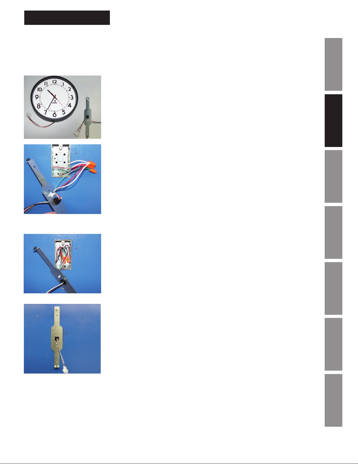
1. Remove the AllSync Plus clock, mounting bracket, and wiring harness
(if applicable) from the packaging.
2. Using UL approved wire nuts, make connections between flying
leads and wiring inside electrical box.
a. Black wire should be connected to hot (run) wire from the master.
b. Red wire should be connected to the correction line from the master
clock.
InstallationIntroduction
Operation
c. White wire should be connected to the neutral line.
d. Green wire should be connected to earth ground.
Note: All wiring connections should be made in accordance to local
and national electrical codes.
3. Bundle all wall wiring and female connector wiring inside back box
and place mounting bracket over back box opening.
4. Attach mounting bracket to back box and wall, ribbed post up.
5. Secure bracket to wall using appropriate mounting screw and anchor
for wall material. Screw and anchor are not included.
TroubleshootingGeneral
Specications
Appendix A
Illumination
© American Time
GlossaryAppendix B LED
7
Page 8
Installation
Plastic Surface Mount Clock Installation (cont)
AllSync Plus Clock Installation
& Operation Manual
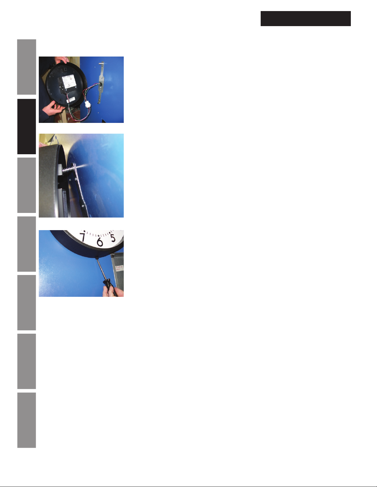
6. Make connection between clock and wall wiring using attached four
conductor mating connectors.
7. Bundle wires inside clock bezel.
Installation Introduction
Operation
Troubleshooting General
Appendix A
Specications
8. Slide keyhole hanger over ribbed hanging stem on mounting bracket
9. Screw bottom portion of clock to mounting bracket
Note: Screw bottom portion of the clock to the point the screw bottoms out.
Do not over tighten.
Caution:
Over tightening may damage clock bezel. If the clock bezel begins to
deform, cease tightening.
Illumination
Glossary Appendix B LED
8
© American Time
Page 9
AllSync Plus Clock Installation
& Operation Manual
Installation
Metal Surface Mount Clock Installation
Warning: The AllSync Plus metal surface mount clock should be mounted according to these
instructions to meet UL clock listing.
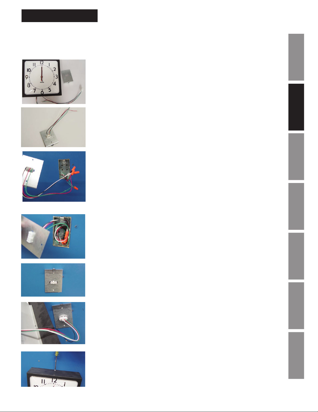
1. Remove the AllSync Plus clock, mounting bracket, and wiring harness (if
applicable) from the packaging.
2. Snap female (wall half) connector into mounting bracket.
3. Using UL approved wire nuts, make connections between flying leads
and wiring inside electrical box.
a. Black wire should be connected to hot (run) wire from the master.
b. Red wire should be connected to the correction line from the
master clock.
c. White wire should be connected to the neutral line.
d. Green wire should be connected to earth ground.
InstallationIntroduction
Operation
TroubleshootingGeneral
Note: All wiring connections should be made in accordance to local and
national electrical codes.
4. Bundle all wall wiring and female connector wiring inside back box
and place mounting bracket over back box opening, bent side up.
5. Screw mounting bracket to electrical box.
6. Connect clock wiring using connector attached to clock.
7. Hang clock on mounting bracket and secure using screw through the top of
the clock.
Specications
Appendix A
Illumination
GlossaryAppendix B LED
© American Time
9
Page 10
Installation
Metal Round Double Dial Clock Installation
Warning:
The AllSync Plus metal double dial clock should be mounted according to these instructions to meet UL
clock listing.
Installation Introduction
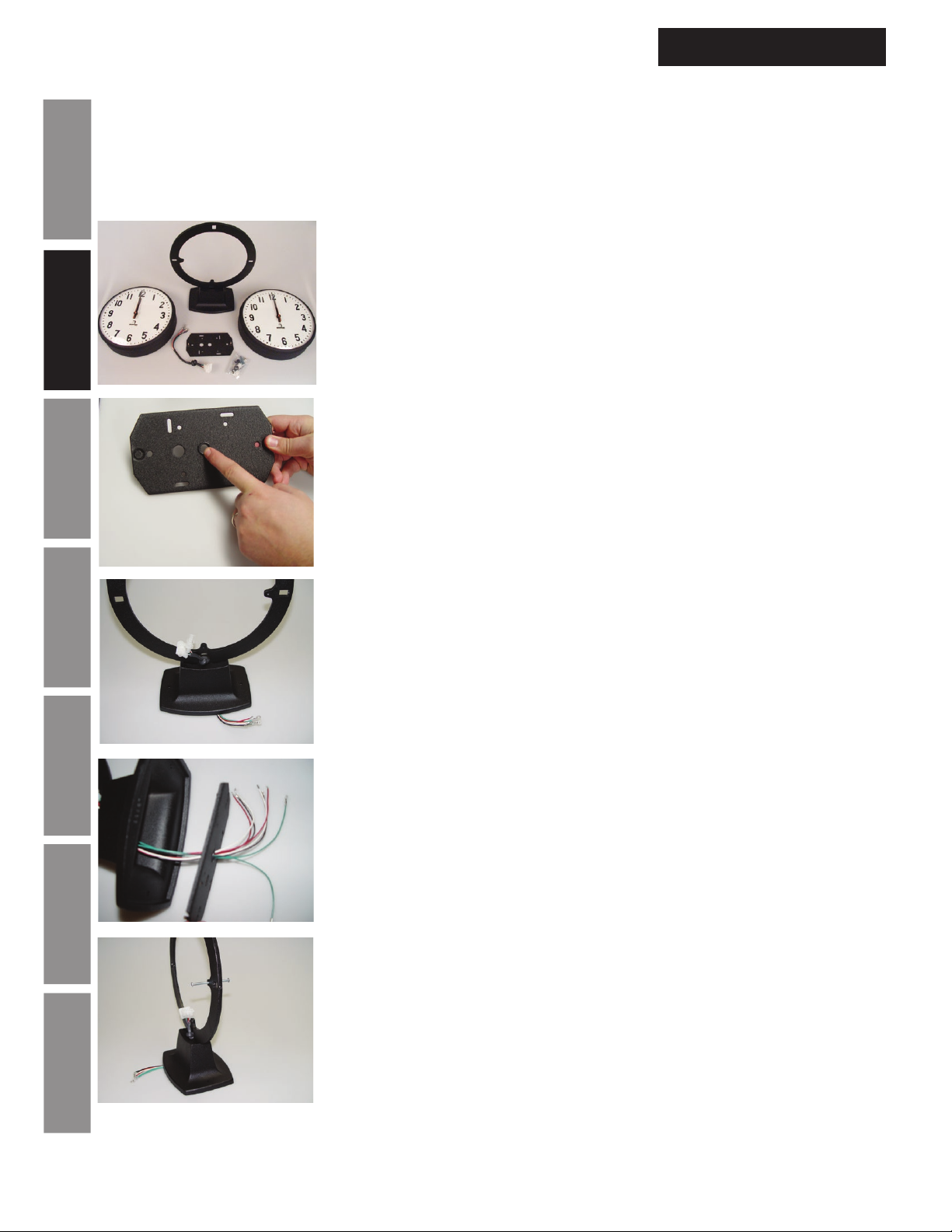
2. Insert plastic bushing into box plate to protect wires
AllSync Plus Clock Installation
& Operation Manual
1. Remove the AllSync Plus clocks, double dial ring, wiring harnesses,
backbox plate and plastic bushings from the packaging.
Operation
Troubleshooting General
Appendix A
Specications
3. Thread back box wire harnesses through double dial ring base and box
plate.
Illumination
Glossary Appendix B LED
10
1
4. Insert 1
/2" screws into either side of double dial ring. Thread both
screws half way through ring using same threaded hole.
Note: ceiling mount screw location should be directly above ring base
and wall mount screw location should be 90 degrees from base. (Wall
mount shown).
© American Time
Page 11
AllSync Plus Clock Installation
& Operation Manual
Installation
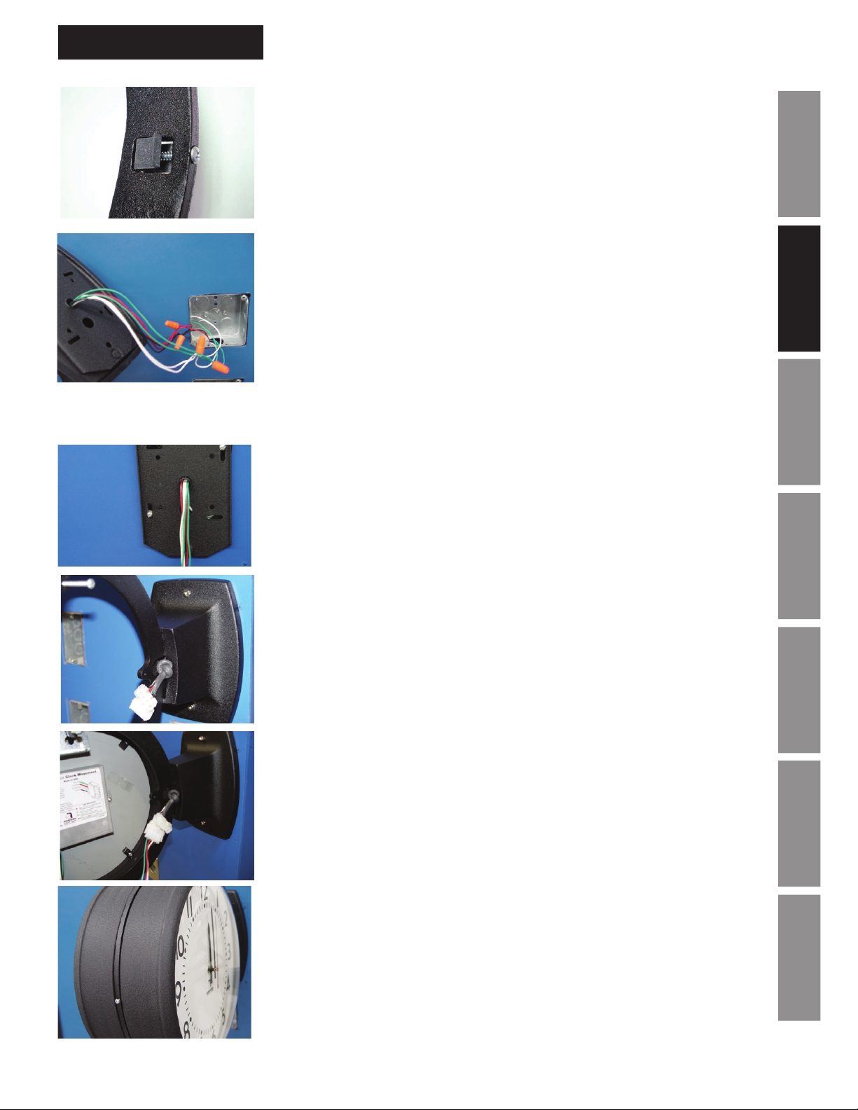
5. Attach mounting clips by threading the 11/4" screws included through
them in each of the three positions. Do not completely tighten, they
should be loose at this point.
6. Using UL approved wire nuts, make connections between flying leads
and wiring inside electrical box.
a. Black wire should be connected to hot (run) wire from the master.
b. Red wire should be connected to the correction line from the
master clock.
c. White wire should be connected to the neutral line.
d. Green wire should be connected to earth ground.
Note: All wiring connections should be made in accordance to local and
national electrical codes
7. Attach box plate to electrical box.
8. Attach double dial ring to box plate using acorn style nuts.
InstallationIntroduction
Operation
TroubleshootingGeneral
9. Hang one side of the double dial clock on mounting ring using protruding
screw and connect clock wires to one of the wall ends.
Note: The knot in the wall side wire harness may block clock installation. By
simply pulling it away from ring base about half an inch will provide adequate
space to install both clock sides.
10. Connect remaining side of double dial clock to remaining wire harness
wall end and hang on remaining screw.
11. Tighten mounting clips installed in step 5 to firmly secure both side of
double dial clock.
Specications
Appendix A
Illumination
GlossaryAppendix B LED
© American Time
11
Page 12
Installation
Plastic Double Dial Clock Installation
Warning:
The AllSync Plus plastic double dial clock should be mounted according to these instructions to meet UL
clock listing.
Installation Introduction
AllSync Plus Clock Installation
& Operation Manual
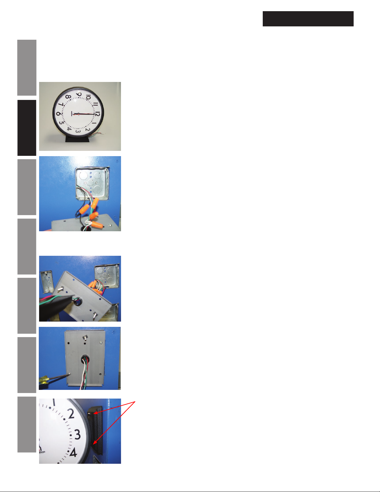
1. Remove the AllSync Plus plastic double dial clock from packaging.
2. Using UL approved wire nuts, make connections between flying leads
and wiring inside electrical box.
a. Black wire should be connected to hot (run) wire from the
master.
Operation
Troubleshooting General
Appendix A
Specications
b. Red wire should be connected to the correction line from the
master clock.
c. White wire should be connected to the neutral line.
d. Green wire should be connected to earth ground.
Note: All wiring connections should be made in accordance to local and
national electrical codes
3. Remove box plate from double dial clock by removing acorn nuts at
base of clock.
4. Bundle wires inside electrical box.
5. Attach box plate to electrical box.
Illumination
Glossary Appendix B LED
12
6. Connect clock to box plate using acorn nuts removed in step 3.
© American Time
Page 13
AllSync Plus Clock Installation
& Operation Manual
Installation
Metal Square Double Dial Clock Installation
Warning:
The AllSync Plus metal square double dial clock should be mounted according to these instructions to
meet UL clock listing.
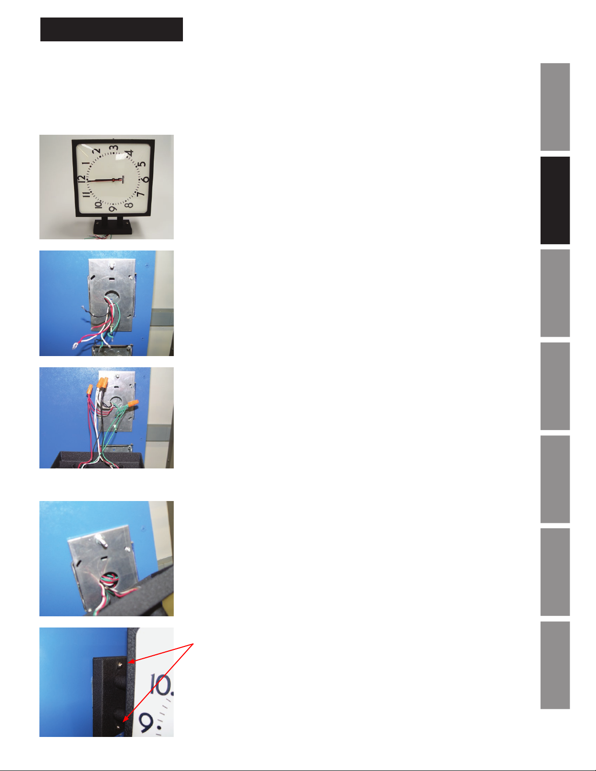
1. Remove the AllSync Plus square metal double dial clock from
packaging.
InstallationIntroduction
2. Remove box plate from clock by removing acorn nuts at the base of the
clock. Pull wall wiring through plate hole and attach to electrical box.
3. Using UL approved wire nuts, make connections between flying leads
and wiring inside back box.
a. Black wire should be connected to hot (run) wire from the master.
b. Red wire should be connected to the correction line from the
master clock.
c. White wire should be connected to the neutral line.
d. Green wire should be connected to earth ground.
Note: All wiring connections should be made in accordance to local and
national electrical codes
4. Bundle wires inside electrical box.
Operation
TroubleshootingGeneral
Specications
Appendix A
Illumination
© American Time
5. Connect clock to box plate using acorn nuts removed in step 2.
GlossaryAppendix B LED
13
Page 14
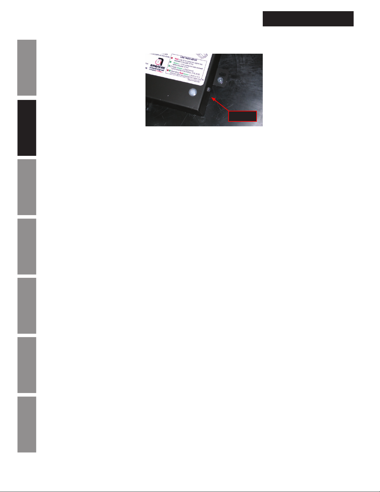
Installation
AllSync Plus Startup Routine
AllSync Plus Clock Installation
& Operation Manual
LED
LED location on back of clock
Installation Introduction
The AllSync Plus clocks operate differently from their fixed clock protocol mechanical counterparts and from the
older AllSync clocks.
After power is initially supplied to the AllSync Plus clock run line the following will occur:
1. The clock will charge its internal backup power cell and undergo startup diagnostics.
Note: This may take from 1-9 minutes. During this charge period the clock will run through the start
Operation
up diagnostics indicated by the LED on the back of the clock and the clock hands will remain still.
2. The second hand will begin slow stepping (moving 1 second on the clock face for every 3 seconds real
time).
Note: This stage will last for approximately 3 minutes. While the second hand is slowly stepping the
LED on the back will flash green. The green flashing LED indicates the microprocessor is telling the
movement what time it is. The default time for the circuit board is 12:50. This is the time the
movement receives on startup and after extended power outages (greater than 15-20 minutes).
Troubleshooting General
3. The clock will rapidly advance and the LED will turn solid red.
Note: The solid red LED indicates the clock circuit board has not received a 12 hour correction.
4. The clock will stop rapid advancement sometime between 12:50 and 1:15 as seen on the clock face
and begin running at the correct pace (1 tick per second).
Note: The rapid advancement of the hands may pause periodically for the clock to find its position.
Appendix A
Rapid advancement will continue shortly after the clock has completed its location check.
Specications
Note: Rapid advancement may last as long as 15 minutes. Total rapid advancement time depends on
hand location prior to startup.
5. When the time on the clock face reaches approximately 2:02, the clock hands will rapidly advance to
match the minutes on the master clock connected to it.
Note: If a master does not send a valid correction, the AllSync Plus clock cannot synchronize its minutes
to the master.
Illumination
Note: The minute and second hands will be on time with the master after this rapid correction.
6. Approximately 5 minutes after the conclusion of the first 12 hour correction from the connected
master the AllSync Plus clock will rapidly advance to match the exact time on of the master (hour
hand will correct).
Note: The AllSync Plus clock is set up at the factory for clock code 01 (xx:57:54 – 8 second hourly
Glossary Appendix B LED
correction, 5:57:54 – 14 second 12 hour correction). If running a different clock protocol, the AllSync
Plus clock may require an additional 12 hour correction to recognize the different clock protocol. If this
is the case, allow 24 hours for the clock to synchronize.
14
© American Time
Page 15

AllSync Plus Clock Installation
& Operation Manual
User Notes
InstallationIntroduction
Operation
TroubleshootingGeneral
Specications
Appendix A
Illumination
© American Time
GlossaryAppendix B LED
15
Page 16

General Operation
AllSync Plus accuracy
The AllSync Plus movement continually makes adjustments to its own internal clock. With each correction
received from your master clock it will make an adjustment to match the time on the master. For this reason,
the longer the AllSync clock is connected to your master the closer it will get to your master’s time. After
approximately 2 days the AllSync Plus clock should be ±1 second to the master system clock.
Movement corrections
The AllSync Plus clock has two primary yet completely separate parts: the circuit board and the movement. The
circuit board listens to your master and tells your movement, when asked, the time in its own language. The
movement will ask for the time 4 times a day at 2am, 8am 2pm and 8pm. For this reason if your master time
is changed, the AllSync Plus clock will not correct until it has both received a correction from the master and
Installation Introduction
reached one of its four daily correction times.
Note: The AllSync Plus clock(s) starts its internal clock at 12:50 when power has been removed from it by more
than about 25 minutes.
AllSync Plus Clock Installation
& Operation Manual
Operation
Troubleshooting General
Appendix A
Specications
Illumination
Glossary Appendix B LED
16
© American Time
Page 17
AllSync Plus Clock Installation
& Operation Manual
General Operation
Start Up Example Operation:
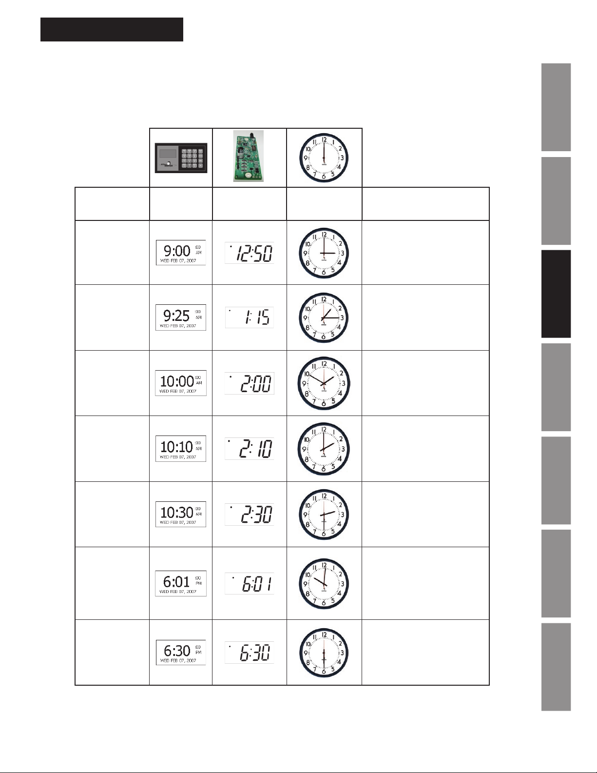
Note: This is an example of how the AllSync Plus clock will operate with an ATS master running clock code
01 and actual (master) plug in time at 9 am.
Timeline
0 minutes
25 minutes
1 hour
Actual Time
(Master
Time)
Clock
Microcontroller
Time shown on
clock
Description
Power is applied to clock
at 9 am actual time with the
clock displaying 3 o’clock.
The clock microcontroller
starts counting at 12:50.
25 minutes after power has
been applied clock face
matches microcontroller
time.
Microcontroller updates
its time using an hourly
correction from master
clock.
InstallationIntroduction
Operation
TroubleshootingGeneral
1 hour
10 minutes
1.5 hours
9 hours
1 minute
9.5 hours
Clock movement requests
time from microcontroller.
Clock movement
synchronizes with clock
microcontroller.
Master clock sends a 12
hour correction out shortly
before 6 o'clock. The
microcontroller resets
clock movement. Clock
movement requests the time.
Clock movement has
finished fast correction and
is now on time with the
master.
Specications
Appendix A
Illumination
GlossaryAppendix B LED
© American Time
17
Page 18
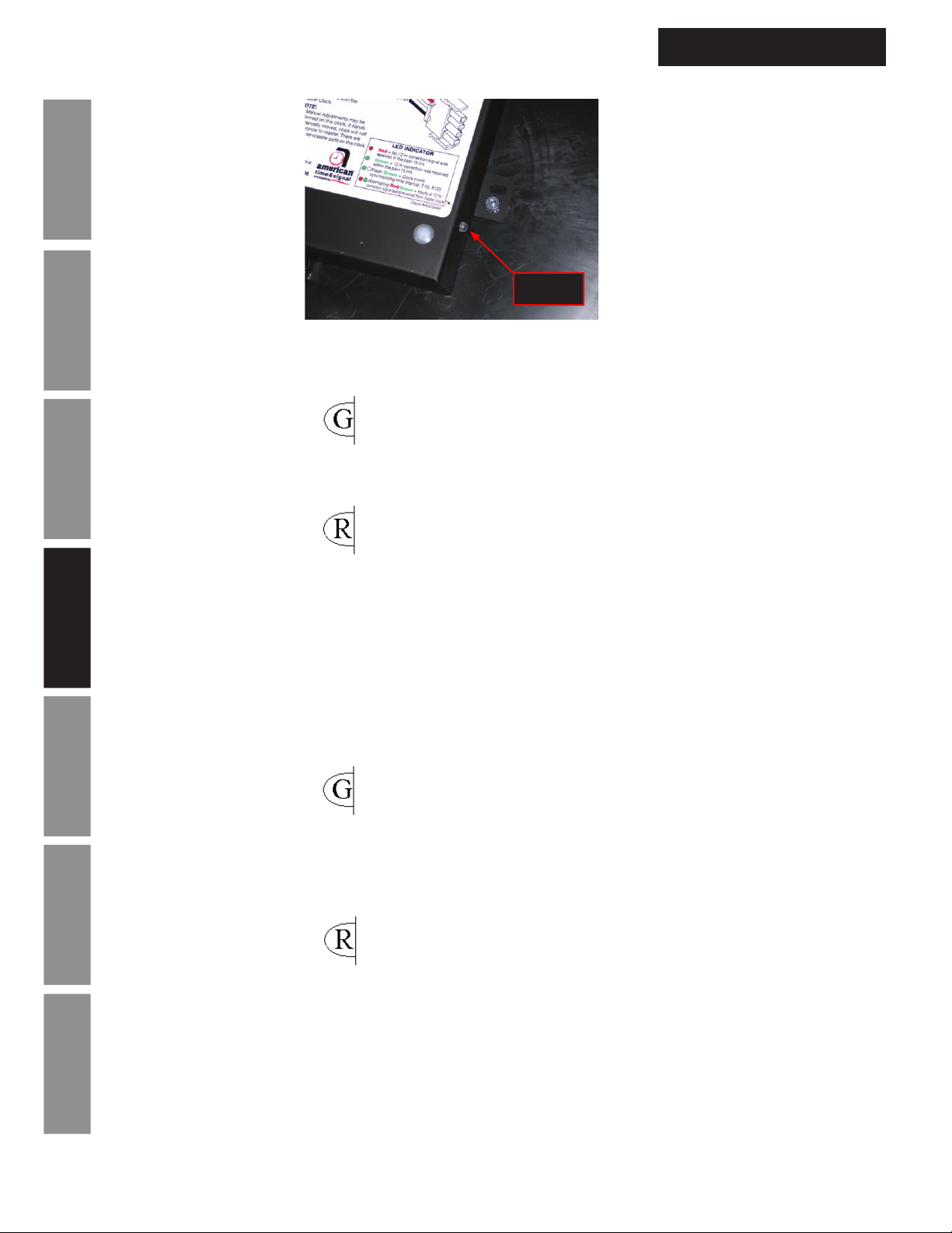
Troubleshooting
Note: The LED indicator on the back of the AllSync Plus clock is intended for troubleshooting purposes.
Installation Introduction
AllSync Plus Clock not correcting the hour hand
• LED is solid green
º Wait for 8:00 or 2:00 on clock face
AllSync Plus Clock Installation
& Operation Manual
LED
º Disconnect clock for 1 hour, reconnect and wait for 24 hours.
Operation
• LED is solid red
º Wait for 12 hour correction
Note: LED on back of clock will alternate red-green while master is sending it a correction.
º If AllSync Plus clock(s) have been moved from one clock protocol to another with identical
hourly correction it may not recognize the switch. Set master for synchronous style correction with
Troubleshooting General
different hourly correction, then, if needed change clock protocol back (refer to your master clock
instructions for setting clock protocol).
AllSync Plus Clock Synchronized to the correct hour and seconds but minutes are off by less than
• LED is green
Appendix A
Specications
º Wait for 8:00 or 2:00 on clock face
Note: LED on back of clock will alternate red-green while master is sending it a correction.
o Clock may have been jarred during shipment. Remove crystal and move the minute hand to the
correct time. Contact American Time Technical support for assistance at 800-328-8996.
• LED is red
Illumination
o Wait for 12 hour correction and clock to cross 8:00 or 2:00
o If AllSync Plus clock has been moved from one clock protocol to another with identical
hourly correction it may not recognize the switch. Set master for synchronous style correction
with different hourly correction, then if needed, change clock protocol back. Refer to your master
clock instructions for setting clock protocol.
Glossary Appendix B LED
18
© American Time
Page 19
AllSync Plus Clock Installation
& Operation Manual
AllSync Plus Clock not running with power applied
• LED not lit
o Verify master clock is wired and operating correctly
o Verify wiring to clock (check voltage using voltmeter)
o Contact American Time Technical support at 800-328-8996
Troubleshooting
Note: You may damage clock by changing power supply settings to 24vac and applying 120vac.
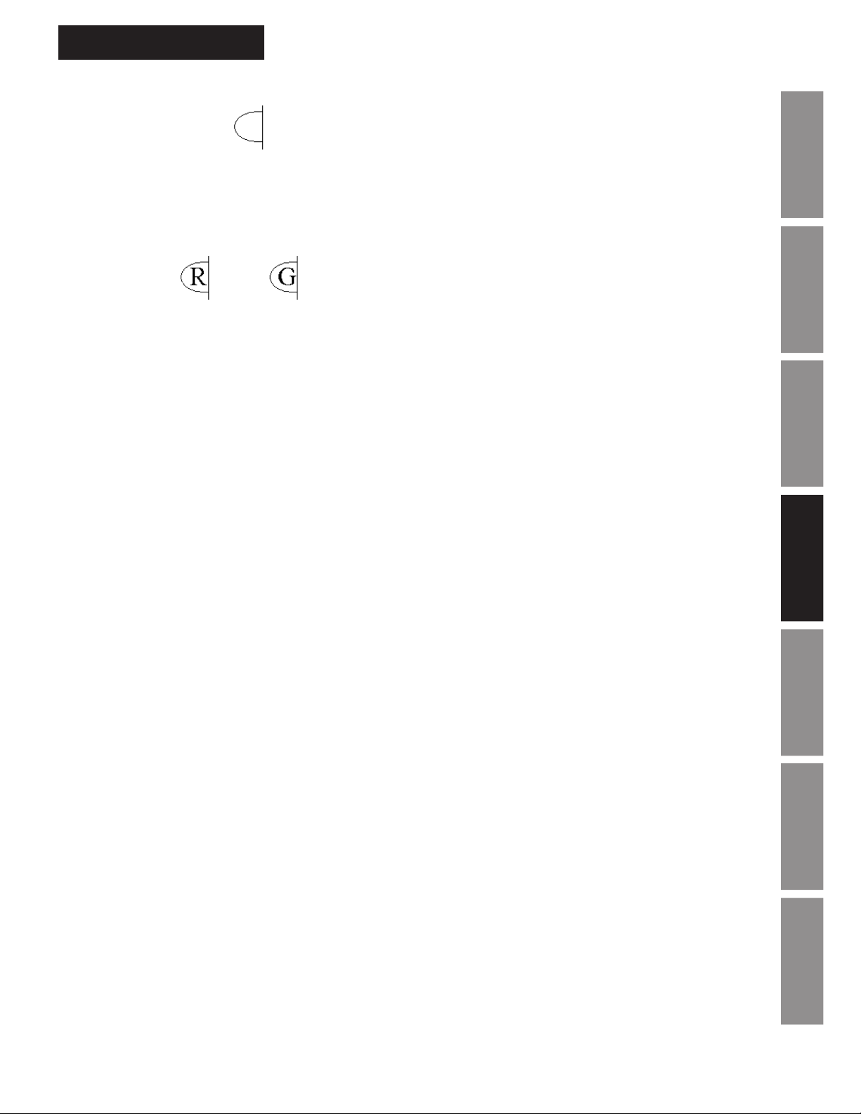
• LED lit or
o Wait for 30 minutes. The AllSync Plus clock requires a short period (up to 15 minutes) to charge its
backup power supply.
o Remove dust cover on the back of the clock and verify connection between circuit board and
movement.
InstallationIntroduction
Operation
TroubleshootingGeneral
Specications
Appendix A
© American Time
Illumination
GlossaryAppendix B LED
19
Page 20
AllSync Plus Clock Specications
AllSync Plus Clock Installation
& Operation Manual
AllSync Plus
®
Flush Metal Case
®
FEATURES
• 5 Year Warranty
• Microprocessor controlled movement
• 15 minutes of backup power (no batteries required)
• Accuracy to within ±1 second of a master clock
Installation Introduction
• Reduced power consumption
• Attractive modern design
• Heavy-duty construction
• All metal case
• Diagnostic LED
DESCRIPTION
Operation
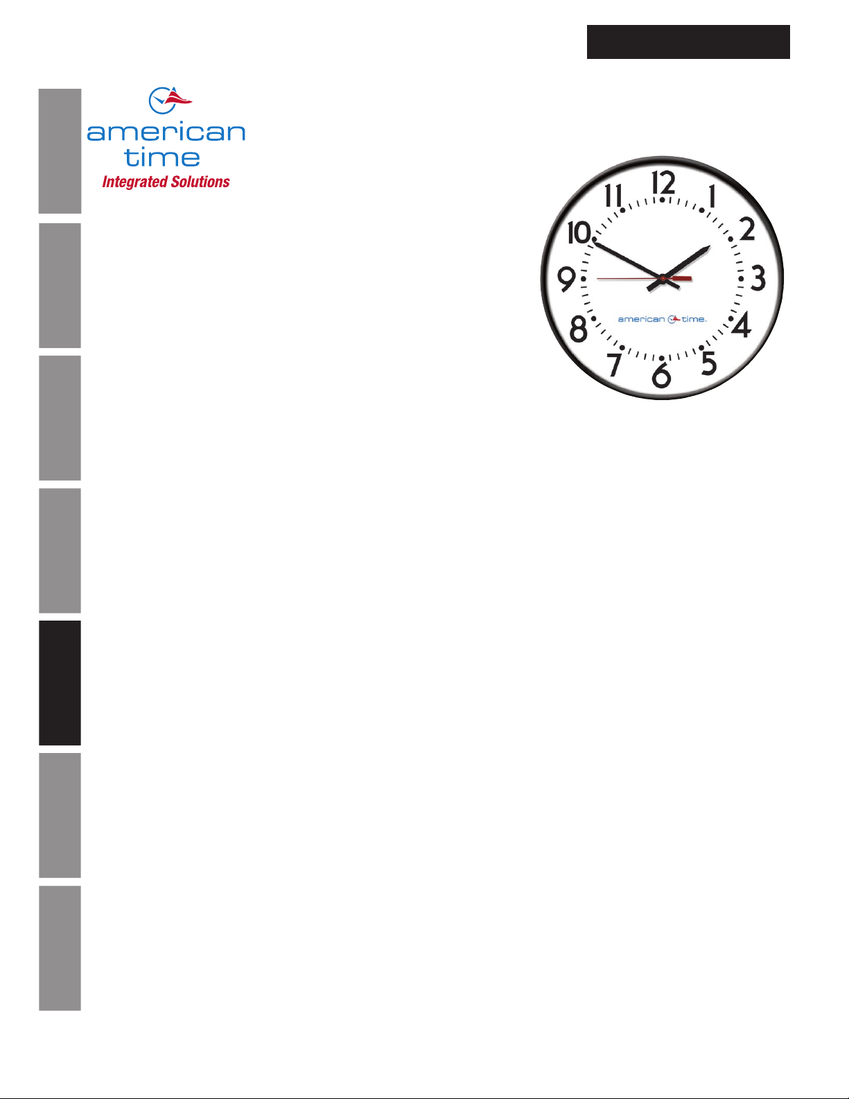
The american time™ AllSync Plus clocks are provided in round or square metal cases with glass crystals and bold, black
numerals and minute markers on a non-yellowing white dial. Stylish hour and minute hands are aluminum with a black finish
and a red sweep second hand.
AllSync Plus clocks are designed to work with multiple master clocks and correction signals. This unit is programmed to
identify the signal it receives from the master and operate as that style of clock. Changing clock operation from one style to
another is as easy as unplugging the clock from one system and plugging it into another. If needed, changing the placement
of 2 small jumpers on the circuit board can change the voltage required to run this clock from 120vac to 24vac or 24vac
to 120vac. This clock provides 15 minutes of backup run power without the use of batteries. If a power outage should last
longer than 15 minutes, the clock will synchronize to the master clock at the hourly and 12 hour correction cycles.
Troubleshooting General
Correction Signals
Works on:
• Hourly correction: 7-9 seconds starting at the 57th minute and 54th second. 12 hour correction: 13-18 seconds starting at
5:57:54 (am and pm).
• Hourly correction: 24-28.5 seconds starting at the 0 minute and 0 second. 12 hour correction: 24-32 minutes starting at
6:00:00 (am and pm).
Appendix A
• *Hourly correction: 54-56 seconds starting at the 58th minute and 5th second. 12 hour correction: 10 pulses of 94-96
Specications
seconds starting at 5:05:00 (am and pm) and repeating every 2 minutes.
• Hourly correction: 24-26 seconds starting at 0 minute and 0 second. 12 hour correction: 25 pulses of 24-26 seconds
starting at 6:00:00 (am and pm) and repeating every 60 seconds.
• Hourly correction: 63-67 seconds starting at the 58th minute and 0 second. 12 hour correction: 14 pulses of 63-67
seconds starting at 5:06:00 (am and pm) and repeating every 2 minutes.
• *Hourly correction: 54-56 seconds starting at the 58th minute and 5th second. 12 hour correction: 12 pulses of 63-67
seconds starting at 5:05:00 (am and pm) repeating every 90 seconds.
Illumination
*Note:
When switching between these correction protocols, you must use a different correction protocol to complete the transition.
The AllSync Plus clock needs to distinguish between hourly corrections before it can change correction protocols internally.
Glossary Appendix B LED
140 3rd St. S, PO Box 707, Dassel, MN 55325
800-328-8996 •
20
american-time.com
Page 1 of 2
PS03010 Rev H
© American Time
Page 21
AllSync Plus Clock Installation
Steel
surface mount
Steel
ush mount
A
B
Flush mount
Surface mount
steel square
A
B
& Operation Manual
AllSync Plus Clock Specications
SPECIFICATIONS
• 24vac/60 Hz or 120vac/60 Hz
• Current draw: 24vac, 1 watt, .043 amps
120vac, 3 watts, .028 amps
Maximum operating voltage: 24vac setting = 40vac
120vac setting = 150vac
Minimum operating voltage: 24vac setting = 15vac
120vac setting = 50vac
GENERAL
Types of secondary clocks compatible with AllSync Plus:
Cincinnati WS*, *D-8, *D-10, *D-12 Series
Dukane 24SS* Series, 240* Series
Edwards *010 & *012 Series
Faraday 2315*, 2316*, 2335*, 2336*, 2380*, 2382*, 2310*, 2320*, 2330*, 2313*, 2314*, 2333*,
1310 through 1431 Series and 2420* through 2431* Series
Honeywell ST402A* Series
Lathem Type SS* Series
National Time *EX-HH and *EX-LL Series
®
Simplex
& IBM 77* Series, 82* Series, 2310 – 92* Series, 6310 – 92* Series
*Indicates more numbers before or after.
ORDERING INFORMATION
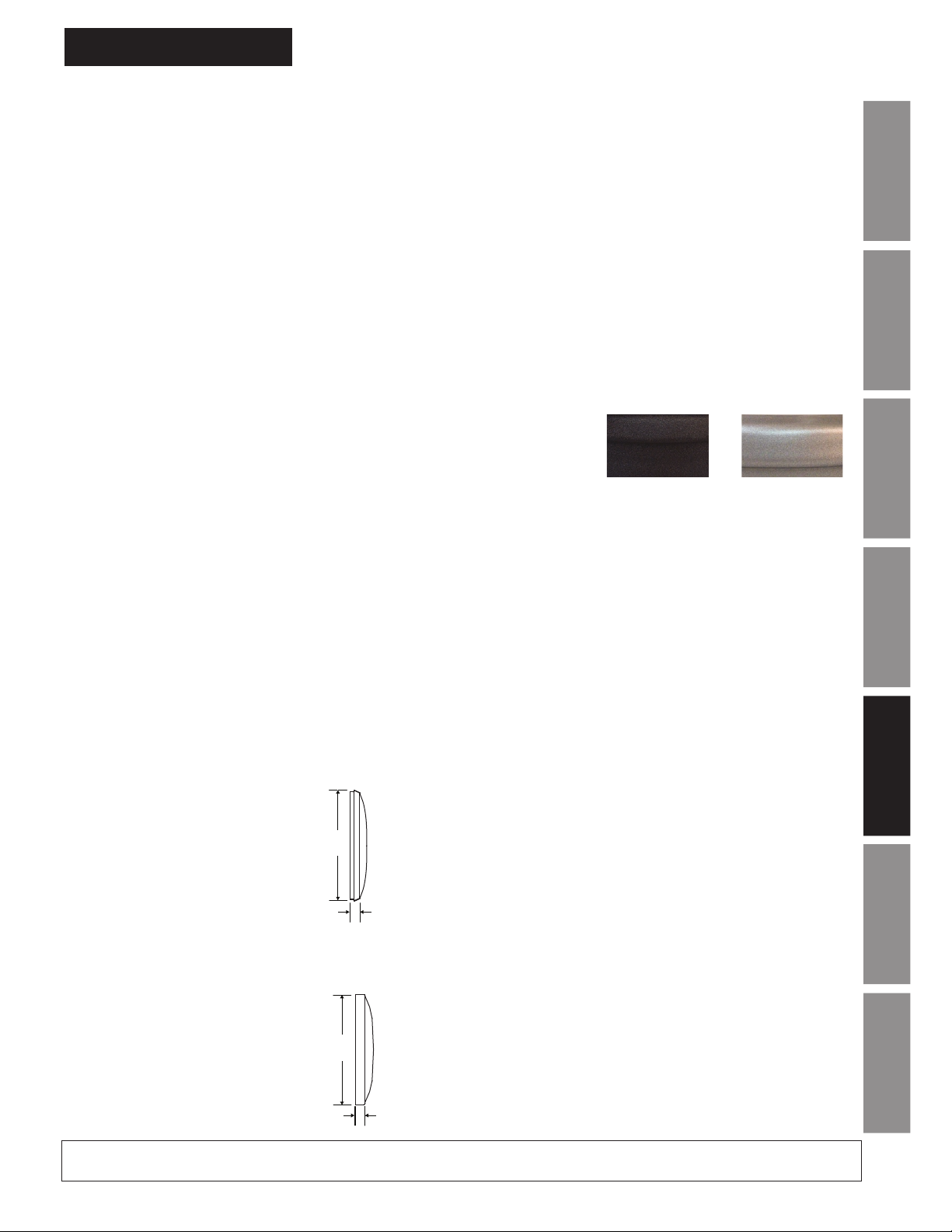
BEZEL FINISHES
Part # Description
U45BHAA?04 10" Rd Flush, Black Sand 120vac
U45BHBA?04 10" Rd Flush, Black Sand 24vac
U55BHAA?04 12" Rd Flush, Black Sand 120vac
U55GHAA?04 12" Rd Flush, Steel Gray 120vac
U55BHBA?04 12" Rd Flush, Black Sand 24vac
U55GHBA?04 12" Rd Flush, Steel Gray 24vac
U58BHAA?04 12" Sq Flush, Black Sand 120vac
Black Sand=BH
Matte finish
Steel Gray=GH
Smooth satin
finish 12" round
only
U58BHBA?04 12" Sq Flush, Black Sand 24vac
U65BHAA?04 15" Rd Flush, Black Sand 120vac
U65BHBA?04 15" Rd Flush, Black Sand 24vac
Note:
Replace the ? in the part number with the number from the list below that will correspond with the system you’re replacing.
New flush mount installations require backboxes.
0 = Faraday 1 = National 5 = Simplex
7 = 2-hook 8 = Setco 9 = R&H (keyhole)
For a plexiglass crystal, replace the BH or GH in the part number with BG or GG.
®
6 = Cincinnati/Edwards
InstallationIntroduction
Operation
TroubleshootingGeneral
Specications
Appendix A
OUTSIDE DIMENSIONS
Round
“A” Dimensions:
1
11
⁄4" for 10" clocks
1
13
A
⁄4" for 12" clocks
16" for 15" clocks
“B” Dimensions:
5
1
B
steel square
⁄8" for 10", 12" & 15" clocks
OUTSIDE DIMENSIONS
Square (12" only)
“A” Dimensions:
5
12
At American Time, we continually strive to improve our products to meet our customers’ needs and to provide the best possible value. The above specifications
are believed to be correct, are subject to change without notice and may otherwise vary from the above. Please call if you need verification of any specifications or
the suitability of a particular product for a particular application.
© American Time
A
B
⁄8" for 12" clocks
“B” Dimensions:
1
1
⁄4" for 12" clocks
Page 2 of 2
PS03010 Rev H
Illumination
GlossaryAppendix B LED
21
Page 22
AllSync Plus Clock Specications
AllSync Plus Clock Installation
& Operation Manual
AllSync Plus
®
Flush Molded Case
®
FEATURES
• 5 Year Warranty
• Microprocessor controlled movement
• 15 minutes of backup power (no batteries required)
• Accuracy to within ±1 second of a master clock
Installation Introduction
• Reduced power consumption
• Attractive modern design
• Impact-resistant black plastic case
• Shatter-resistant polycarbonate crystal
• Diagnostic LED
DESCRIPTION
Operation
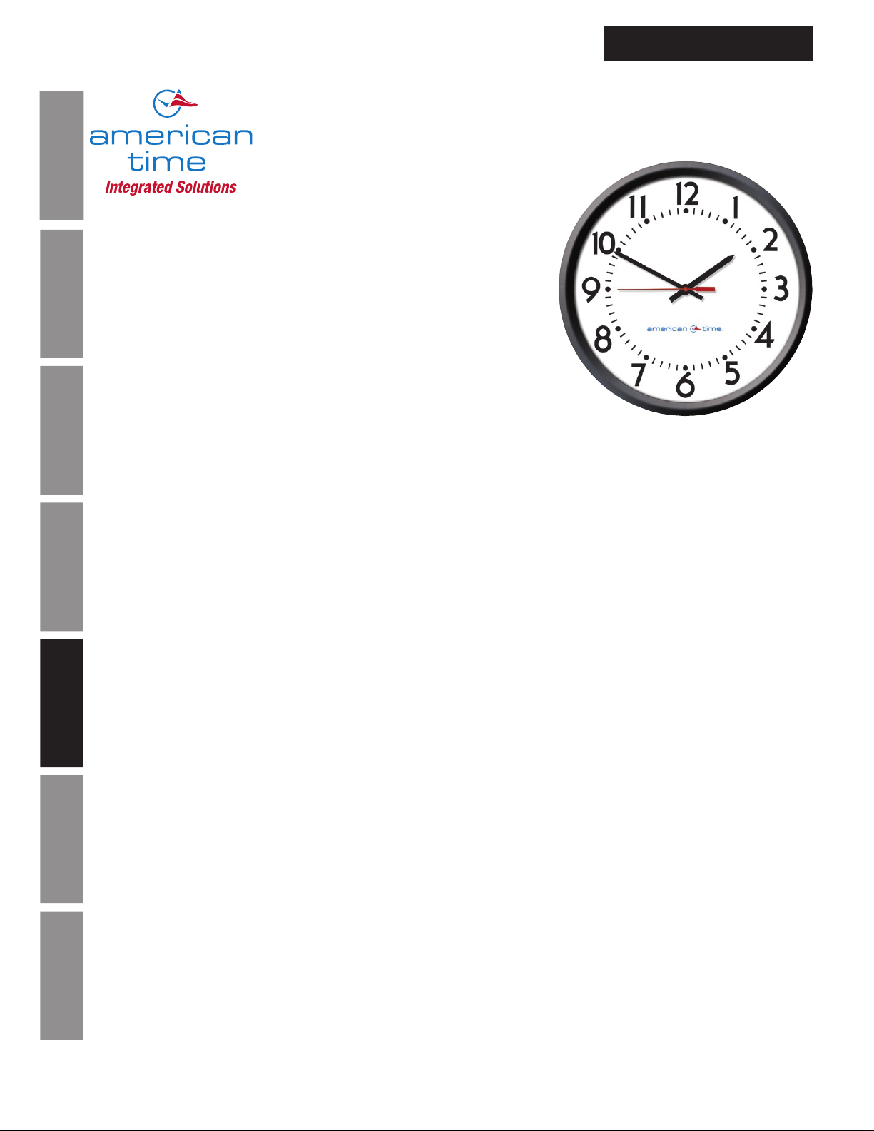
The american time™ AllSync Plus clocks are provided in round only high impact black plastic cases with clear
polycarbonate crystals and bold, black numerals and minute markers on a non-yellowing white dial. Stylish hour and minute
hands are aluminum with a black finish and a red sweep hand. Other bezel colors available. Consult factory.
AllSync Plus clocks are designed to work with multiple master clocks and correction signals. This unit is programmed to
identify the signal it receives from the master and operate as that style of clock. Changing clock operation from one style to
another is as easy as unplugging the clock from one system and plugging it into another. If needed, changing the placement
of 2 small jumpers on the circuit board can change the voltage required to run this clock from 120vac to 24vac or 24vac
to 120vac. This clock provides 15 minutes of backup run power without the use of batteries. If a power outage should last
longer than 15 minutes, the clock will synchronize to the master clock at the hourly and 12 hour correction cycles.
Troubleshooting General
Correction Signals
Works on:
• Hourly correction: 7-9 seconds starting at the 57th minute and 54th second. 12 hour correction: 13-18 seconds starting at
5:57:54 (am and pm).
• Hourly correction: 24-28.5 seconds starting at the 0 minute and 0 second. 12 hour correction: 24-32 minutes starting at
Appendix A
6:00:00 (am and pm).
Specications
• *Hourly correction: 54-56 seconds starting at the 58th minute and 5th second. 12 hour correction: 10 pulses of 94-96
seconds starting at 5:05:00 (am and pm) and repeating every 2 minutes.
• Hourly correction: 24-26 seconds starting at 0 minute and 0 second. 12 hour correction: 25 pulses of 24-26 seconds
starting at 6:00:00 (am and pm) and repeating every 60 seconds.
• Hourly correction: 63-67 seconds starting at the 58th minute and 0 second. 12 hour correction: 14 pulses of 63-67
seconds starting at 5:06:00 (am and pm) and repeating every 2 minutes.
• *Hourly correction: 54-56 seconds starting at the 58th minute and 5th second. 12 hour correction: 12 pulses of 63-67
Illumination
seconds starting at 5:05:00 (am and pm) repeating every 90 seconds.
*Note:
When switching between these correction protocols, you must use a different correction protocol to complete the transition.
The AllSync Plus clock needs to distinguish between hourly corrections before it can change correction protocols internally.
Glossary Appendix B LED
140 3rd St. S, PO Box 707, Dassel, MN 55325
800-328-8996 •
22
american-time.com
Page 1 of 2
PS03011 Rev J
© American Time
Page 23
AllSync Plus Clock Installation
Surface
mount plastic
Flush
mount plastic
B
A
& Operation Manual
AllSync Plus Clock Specications
SPECIFICATIONS
• 24vac/60 Hz or 120vac/60 Hz
• Current draw: 24vac, 1 watt, .043 amps
120vac, 3 watts, .028 amps
GENERAL
Maximum operating voltage: 24vac setting = 40vac
120vac setting = 150vac
Minimum operating voltage: 24vac setting = 15vac
120vac setting = 50vac
Types of secondary clocks compatible with AllSync Plus:
Cincinnati WS*, *D-8, *D-10, *D-12 Series
Dukane 24SS* Series, 240* Series
Edwards *010 & *012 Series
Faraday 2315*, 2316*, 2335*, 2336*, 2380*, 2382*, 2310*, 2320*, 2330*, 2313*, 2314*, 2333*,
1310 through 1431 Series and 2420* through 2431* Series
Honeywell ST402A* Series
Lathem Type SS* Series
National Time *EX-HH and *EX-LL Series
Simplex
®
& IBM 77* Series, 82* Series, 2310 – 92* Series, 6310 – 92* Series
*Indicates more numbers before or after.
ORDERING INFORMATION
Part # Description
U45BAAA?04 10" Rd Flush 120vac
U45BABA?04 10" Rd Flush 24vac
U55BAAA?04 12" Rd Flush 120vac
U55BABA?04 12" Rd Flush 24vac
U65BAAA?04 15" Rd Flush 120vac
U65BABA?04 15" Rd Flush 24vac
Note:
Replace the ? in the part number with the number from the list below that will correspond with the system you’re replacing.
New flush mount installations require backboxes.
0 = Faraday 1 = National 5 = Simplex
7 = 2-hook 8 = Setco 9 = R&H (keyhole)
®
6 = Cincinnati/Edwards
InstallationIntroduction
Operation
TroubleshootingGeneral
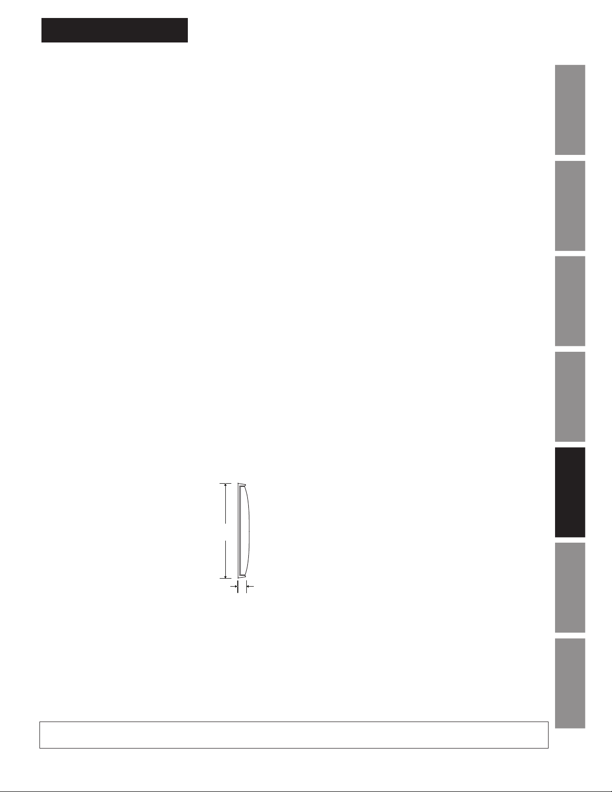
OUTSIDE
DIMENSIONS
FLUSH MOUNT
A
B
At American Time, we continually strive to improve our products to meet our customers’ needs and to provide the best possible value. The above specifications
are believed to be correct, are subject to change without notice and may otherwise vary from the above. Please call if you need verification of any specifications
or the suitability of a particular product for a particular application.
SIZE A B
10" 9
12" 13
7
⁄8" 13⁄8"
1
⁄4" 2"
15" 16" 2"
Specications
Appendix A
Illumination
GlossaryAppendix B LED
© American Time
Page 2 of 2
PS03011 Rev J
23
Page 24
AllSync Plus Clock Specicatios
AllSync Plus Clock Installation
& Operation Manual
AllSync Plus
®
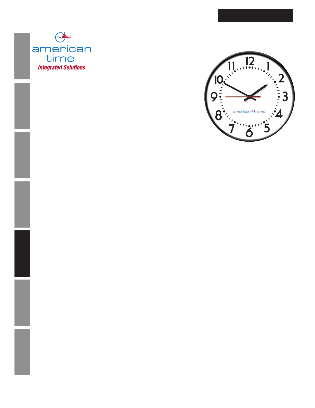
Dual Motor
Metal Case
®
FEATURES
• 5 Year Warranty
• UL/cUL Listed - 12" and 15" surface mount only
• Microprocessor controlled movement
• 15 minutes of backup power (no batteries required)
• Accuracy to within ±1 second of a master clock
• Reduced power consumption
Installation Introduction
• Attractive modern design
• Heavy-duty construction
• All metal case
• Diagnostic LED
DESCRIPTION
The american time™ AllSync Plus clocks are provided in round or square metal cases with glass crystals and bold, black
numerals and minute markers on a non-yellowing white dial. Stylish hour and minute hands are aluminum with a black finish
and a red sweep second hand.
Operation
™
The american time
programmed to identify the signal it receives from the master and operate as that style of clock. Changing clock operation
from one style to another is as easy as unplugging the clock from one system and plugging it into another. If needed,
changing the placement of 2 small jumpers on the circuit board can change the voltage required to run this clock from
120vac to 24vac or 24vac to 120vac. This clock provides 15 minutes of backup run power without the use of batteries. If a
power outage should last longer than 15 minutes, the clock will synchronize to the master clock at the hourly and 12 hour
correction cycles.
AllSync Plus clock is designed to work with multiple master clocks and correction signals. This unit is
Correction Signals
Works on:
Troubleshooting General
• Hourly Correction: 28.75-35 seconds starting at the 59th minute and 30th second. 12 hour correction: 13 minutes and 52
seconds-18 minutes and 8 seconds starting at 5:12:00 (am and pm). Note: This protocol switches off the run line during
the hourly correction.
ORDERING INFORMATION
Part # Description
U45BHGA404 10" Rd Surface 120vac
Appendix A
U45BHGA?04 10" Rd Flush 120vac
Specications
U54BHGA404 12" Rd Surface 120vac
U55BHGA?04 12" Rd Flush 120vac
U57BHGA404 12" Sq Surface 120vac
U58BHGA?04 12" Sq Flush 120vac
U64BHGA404 15" Rd Surface 120vac
U65BHGA?04 15" Rd Flush 120vac
U53BHGA204 12" Rd Double dial wall 120vac
U52BHGA204 12" Rd Double dial ceiling 120vac
Illumination
U51BHGA204 12" Sq Double dial wall 120vac
U50BHGA204 12" Sq Double dial ceiling 120vac
U63BHGA204 15" Rd Double dial wall 120vac
U62BHGA204 15" Rd Double dial ceiling 120vac
Part # Description
U45BHHA404 10" Rd Surface 24vac
U45BHHA?04 10" Rd Flush 24vac
U54BHHA404 12" Rd Surface 24vac
U55BHHA?04 12" Rd Flush 24vac
U57BHHA404 12" Sq Surface 24vac
U58BHHA?04 12" Sq Flush 24vac
U64BHHA404 15" Rd Surface 24vac
U65BHHA?04 15" Rd Flush 24vac
U53BHHA204 12" Rd Double dial wall 24vac
U52BHHA204 12" Rd Double dial ceiling 24vac
U51BHHA204 12" Sq Double dial wall 24vac
U50BHHA204 12" Sq Double dial ceiling 24vac
U63BHHA204 15" Rd Double dial wall 24vac
U62BHHA204 15" Rd Double dial ceiling 24vac
Note:
Replace the ? in the part number with the number from the list below that will correspond with the system you’re replacing.
New flush mount installations require backboxes.
0 = Faraday 1 = National 5 = Simplex
Glossary Appendix B LED
7 = 2-hook 8 = Setco 9 = R&H (keyhole)
Also available in Steel Gray. Replace the BH in part number with GH - i.e. U54BHGA404 to U54GHGA404
®
6 = Cincinnati/Edwards
24
140 3rd St. S, PO Box 707, Dassel, MN 55325
800-328-8996 •
american-time.com
Page 1 of 2
PS03046 Rev G
© American Time
Page 25
AllSync Plus Clock Installation
Steel
surface mount
Steel
ush mount
Flush mount
Surface mount
Ceiling mount round steel
Ceiling mount steel square
& Operation Manual
AllSync Plus Clock Specications
SPECIFICATIONS
• 24vac/60 Hz or 120vac/60 Hz
• Current draw: Single dial:
24vac, 1 watt, .043 amps
120vac, 3 watts, .028 amps
Maximum operating voltage: 24vac setting = 40vac
120vac setting = 150vac
Minimum operating voltage: 24vac setting = 15vac
120vac setting = 50vac
Double dial:
24vac, 2 watt, .086 amps
120vac, 6 watts, .056 amps
GENERAL
Types of secondary clocks compatible with AllSync Plus:
American Time X* Series
™
Standard
Electric CR & GRC 109106 through 109155 Series and 105047 through 105066 Series
*Indicates more numbers before or after.
A A
B
BEZEL
FINISHES
Black Sand=BH
Matte finish
Steel Gray=GH
Smooth satin finish
12" round only
Wall mount round steel
double dial
B
steel square
A
Wall mount steel square
double dial mechanical
B
A
B
A
B
double dial
B
A
steel square
A
B
double dial mechanical
B
A
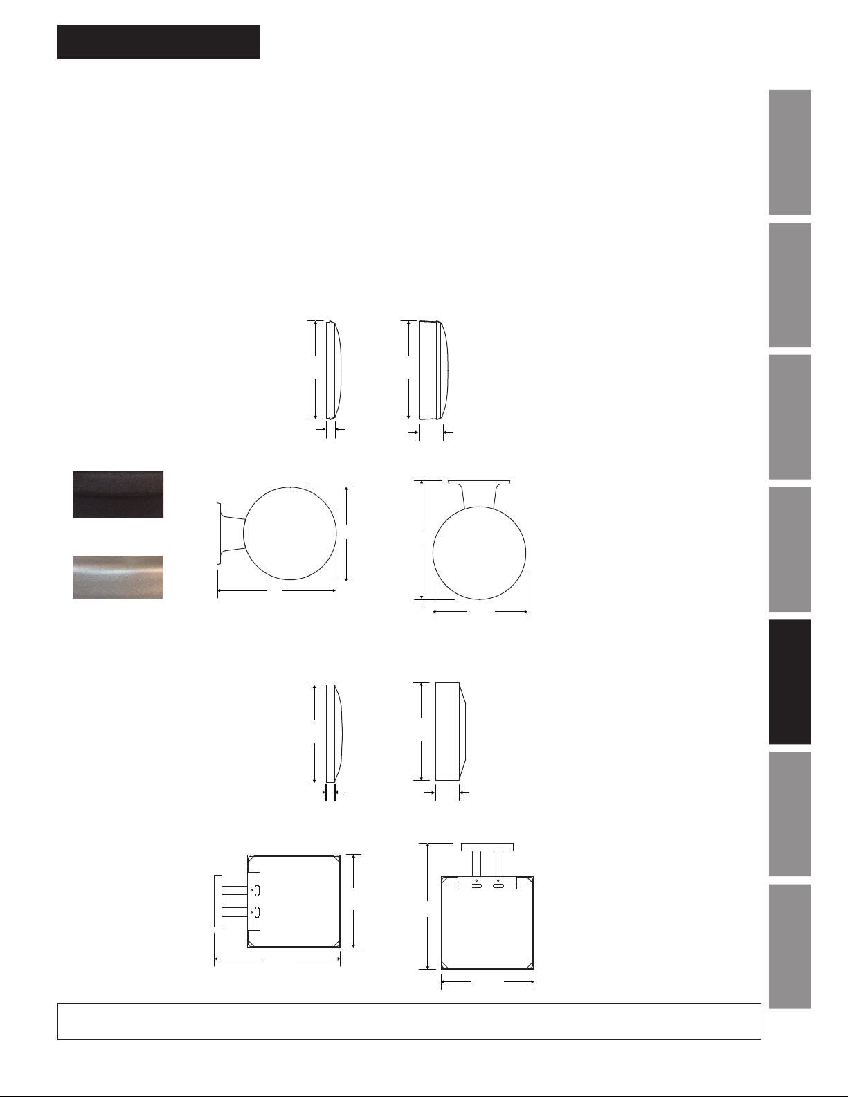
OUTSIDE DIMENSIONS
“A” Dimensions: Surface
1
11
⁄4" for 10" clocks
1
13
⁄4" for 12" clocks
1
16
⁄4" for 15" clocks
“B” Dimensions: Surface
1
2
⁄4" for 10", 12" & 15" clocks
“A” Dimensions: Flush
1
11
/4" for 10" clocks
1
13
⁄4" for 12" clocks
16" for 15" clocks
“B” Dimensions: Flush
5
1
⁄8" for 10", 12" & 15" clocks
“A” Dimensions: Double dial
1
13
⁄4" for 12"clocks
1
16
⁄4" for 15" clocks
“B” Dimensions: Double dial
7
16
⁄8" for 12"clocks
7
19
⁄8" for 15" clocks
OUTSIDE DIMENSIONS
Square (12" only)
“A” Dimensions: Surface
5
12
⁄8" for 12" clocks
“B” Dimensions: Surface
1
3
⁄4" for 12" clocks
“A” Dimensions: Flush
5
12
⁄8" for 12" clocks
“B” Dimensions: Flush
1
1
⁄4" for 12" clocks
“A” Dimensions: Double dial
5
12
⁄8" for 12" clocks
“B” Dimensions: Double dial
1
17
⁄8" for 12" clocks
Double dial mounting requires
a 4" square electrical box in the
wall or ceiling.
InstallationIntroduction
Operation
TroubleshootingGeneral
Specications
Appendix A
Illumination
GlossaryAppendix B LED
At American Time, we continually strive to improve our products to meet our customers’ needs and to provide the best possible value. The above specifications
are believed to be correct, are subject to change without notice and may otherwise vary from the above. Please call if you need verification of any specifications
or the suitability of a particular product for a particular application.
© American Time
Page 2 of 2
PS03046 Rev G
25
Page 26
AllSync Plus Clock Specications
AllSync Plus Clock Installation
& Operation Manual
AllSync Plus
®
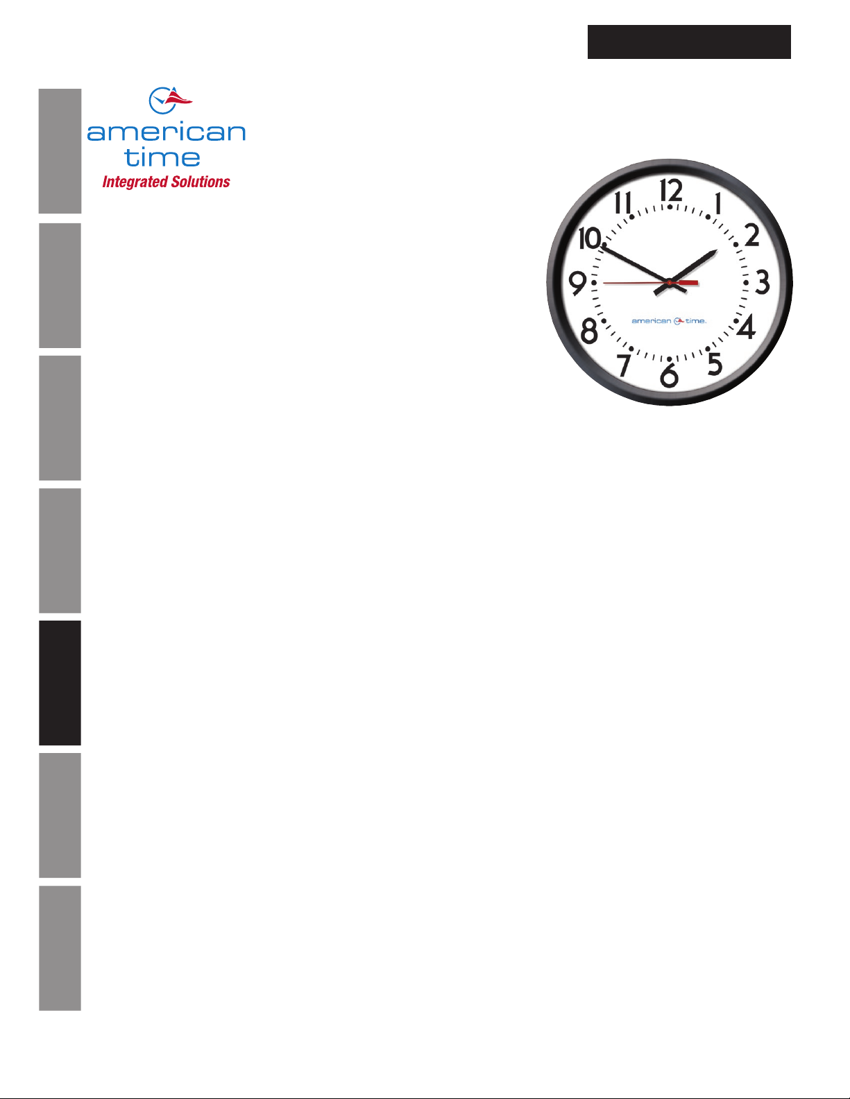
Dual Motor
Molded Case
®
FEATURES
• 5 Year Warranty
• UL/cUL Listed - 12" surface mount only
• Microprocessor controlled movement
• 15 minutes of backup power (no batteries required)
• Accuracy to within ±1 second of a master clock
Installation Introduction
• Reduced power consumption
• Attractive modern design
• Impact-resistant black plastic case
• Shatter-resistant safety crystal
• Diagnostic LED
DESCRIPTION
Operation
The american time™ AllSync Plus clocks are provided in round only high impact black plastic cases with clear
polycarbonate crystals and bold, black numerals and minute markers on a non-yellowing white dial. Stylish hour and minute
hands are aluminum with a black finish and a red sweep hand. Other bezel colors available. Consult factory.
The american time
programmed to identify the signal it receives from the master and operate as that style of clock. Changing clock operation
from one style to another is as easy as unplugging the clock from one system and plugging it into another. If needed,
changing the placement of 2 small jumpers on the circuit board can change the voltage required to run this clock from
120vac to 24vac or 24vac to 120vac. This clock provides 15 minutes of backup run power without the use of batteries. If a
power outage should last longer than 15 minutes, the clock will synchronize to the master clock at the hourly and 12 hour
Troubleshooting General
correction cycles.
™
AllSync Plus clock is designed to work with multiple master clocks and correction signals. This unit is
Correction Signals
Works on:
• Hourly Correction: 28.75-35 seconds starting at the 59th minute and 30th second. 12 hour correction: 13 minutes and 52
seconds-18 minutes and 8 seconds starting at 5:12:00 (am and pm). Note: This protocol switches off the run line during
Appendix A
Glossary Appendix B LED
the hourly correction.
Specications
ORDERING INFORMATION
Part # Description Part # Description
U44BAGA904 10" Rd Surface 120vac U44BAHA904 10" Rd Surface 24vac
U45BAGA?04 10" Rd Flush 120vac U45BAHA?04 10" Rd Flush 24vac
U54BAGA304 12" Rd Surface 120vac U54BAHA304 12" Rd Surface 24vac
U55BAGA?04 12" Rd Flush 120vac U55BAHA?04 12" Rd Flush 24vac
U53BAGA204 12" Rd Double dial wall 120vac U53BAHA204 12" Rd Double dial wall 24vac
Illumination
U52BAGA204 12" Rd Double dial ceiling 120vac U52BAHA204 12" Rd Double dial ceiling 24vac
Note:
Double dial mounting requires a 4" square electrical box in the wall or ceiling.
Surface clocks have a molded in hanger in the plastic cases.
12" surface clocks come complete with security bracket
Replace the ? in the part number with the number from the list below that will correspond with the system you’re replacing.
New flush mount installations require backboxes.
®
0 = Faraday 1 = National 5 = Simplex
7 = 2-hook 8 = Setco 9 = R&H (keyhole)
6 = Cincinnati/Edwards
26
140 3rd St. S, PO Box 707, Dassel, MN 55325
800-328-8996 •
american-time.com
Page 1 of 2
PS03047 Rev G
© American Time
Page 27
AllSync Plus Clock Installation
Wall mount plastic
Ceiling mount plastic
Surface
mount plastic
Flush
mount plastic
B
A
Surface
mount plastic
& Operation Manual
SPECIFICATIONS
• 24vac/60 Hz or 120vac/60 Hz
• Current draw: Single dial:
24vac, 1 watt, .043 amps
120vac, 3 watts, .028 amps
Double dial:
Maximum operating voltage: 24vac setting = 40vac
120vac setting = 150vac
Minimum operating voltage: 24vac setting = 15vac
120vac setting = 50vac
24vac, 2 watt, .086 amps
120vac, 3 watts, .056 amps
GENERAL
Types of secondary clocks compatible with AllSync Plus:
American Time X* Series
™
Standard
Electric CR & GRC 109106 through 109155 Series and 105047 through 105066 Series
*Indicates more numbers before or after.
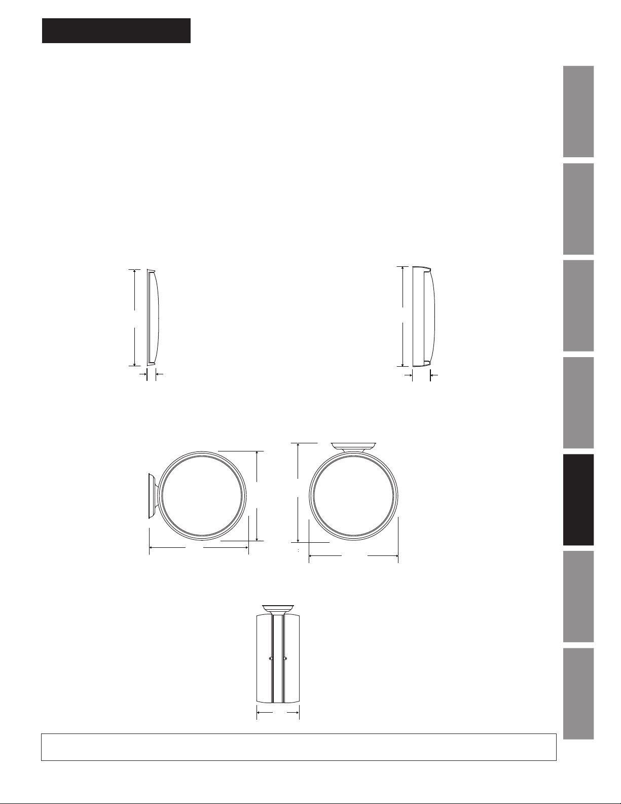
OUTSIDE DIMENSIONS
SIZE A B
10" 9
12" 13
SIZE A B
A
10" 10
12" 13
7
Surface
AllSync Plus Clock Specications
Flush
⁄8" 13⁄8"
1
⁄4" 2"
3
⁄8" 21⁄2"
1
⁄4" 21⁄2"
A
InstallationIntroduction
Operation
B
double dial
B
Double Dial
SIZE A B C
12" 13
1
⁄4" 15" 85⁄8"
Double Dial 12" only
A
Plastic double
dial prole
B
double dial
A
TroubleshootingGeneral
B
Specications
Appendix A
Illumination
C
At American Time, we continually strive to improve our products to meet our customers’ needs and to provide the best possible value. The above specifications
are believed to be correct, are subject to change without notice and may otherwise vary from the above. Please call if you need verification of any specifications
or the suitability of a particular product for a particular application.
© American Time
Page 2 of 2
PS03047 Rev G
GlossaryAppendix B LED
27
Page 28
AllSync Plus Clock Specications
AllSync Plus Clock Installation
& Operation Manual
AllSync Plus
®
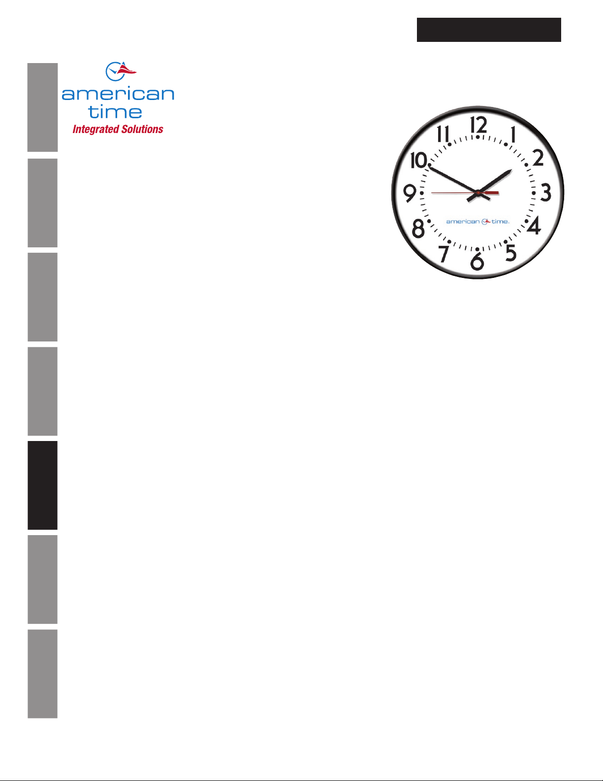
Surface and Double Dial Metal Case
®
FEATURES
• 5 Year Warranty
• UL Listed - 12" and 15" round, surface mount only
• Microprocessor controlled movement
• 15 minutes of backup power (no batteries required)
• Accuracy to within ±1 second of a master clock
Installation Introduction
• Reduced power consumption
• Attractive modern design
• Heavy-duty construction
• All metal case
• Diagonostic LED
• Optional plexiglass crystal available
DESCRIPTION
Operation
The american time™ AllSync Plus clocks, with are provided in round or square metal cases with glass crystals and bold, black
numerals and minute markers on a non-yellowing white dial. Stylish hour and minute hands are aluminum with a black finish and a
red sweep second hand.
™
The american time
programmed to identify the signal it receives from the master and operate as that style of clock. Changing clock operation from
one style to another is as easy as unplugging the clock from one system and plugging it into another. If needed, changing the
placement of 2 small jumpers on the circuit board can change the voltage required to run this clock from 120vac to 24vac or
24vac to 120vac. This clock provides 15 minutes of backup run power without the use of batteries. If a power outage should last
longer than 15 minutes, the clock will synchronize to the master clock at the hourly and 12 hour correction cycles.
Troubleshooting General
Correction Signals
Works on:
• Hourly correction: 7-9 seconds starting at the 57th minute and 54th second. 12 hour correction: 13-18 seconds starting at
5:57:54 (am and pm).
• Hourly correction: 24-28.5 seconds starting at the 0 minute and 0 second. 12 hour correction: 24-32 minutes starting at 6:00:00
(am and pm).
Appendix A
• *Hourly correction: 54-56 seconds starting at the 58th minute and 5th second. 12 hour correction: 10 pulses of 94-96 seconds
Specications
starting at 5:05:00 (am and pm) and repeating every 2 minutes.
• Hourly correction: 24-26 seconds starting at 0 minute and 0 second. 12 hour correction: 25 pulses of 24-26 seconds starting at
6:00:00 (am and pm) and repeating every 60 seconds.
• Hourly correction: 63-67 seconds starting at the 58th minute and 0 second. 12 hour correction: 14 pulses of 63-67 seconds
starting at 5:06:00 (am and pm) and repeating every 2 minutes.
• *Hourly correction: 54-56 seconds starting at the 58th minute and 5th second. 12 hour correction: 12 pulses of 63-67 seconds
starting at 5:05:00 (am and pm) repeating every 90 seconds.
Illumination
*Note:
When switching between these correction protocols, you must use a different correction protocol to complete the transition. The
AllSync Plus clock needs to distinguish between hourly corrections before it can change correction protocols internally.
AllSync Plus clock is designed to work with multiple master clocks and correction signals. This unit is
Glossary Appendix B LED
140 3rd St. S, PO Box 707, Dassel, MN 55325
800-328-8996 •
28
american-time.com
Page 1 of 2
PS03058 Rev D
© American Time
Page 29
AllSync Plus Clock Installation
Steel
surface mount
Surface mount
Ceiling mount round steel
Ceiling mount steel square
& Operation Manual
AllSync Plus Clock Specications
SPECIFICATIONS
• 24vac/60 Hz or 120vac/60 Hz
• Current draw: Single dial:
24vac, 1 watt, .043 amps
120vac, 3 watts, .028 amps
Double dial:
24vac, 2 watts, .086 amps
120vac, 6 watts, .056 amps
Maximum operating voltage: 24vac setting = 40vac
110vac setting = 150vac
Minimum operating voltage: 24vac setting = 15vac
110vac setting = 50vac
GENERAL
Types of secondary clocks compatible with AllSync Plus:
Cincinnati WS*, *D-8, *D-10, *D-12 Series
Dukane 24SS* Series, 240* Series
Edwards *010 & *012 Series
Faraday 2315*, 2316*, 2335*, 2336*, 2370*, 2372*, 2380*, 2382*, 2311*, 2320*, 2331*, 2314*,
1310 through 1431 Series and 2420* through 2431* Series
Honeywell ST402A* Series
Lathem Type SS* Series
National Time *EX-HH and *EX-LL Series
®
Simplex
& IBM 77* Series, 82* Series, 2310 – 92* Series, 6310 – 92* Series
*Indicates more numbers before or after.
ORDERING INFORMATION
Part # Description
U54BHAA404 12" Rd Surface 120vac
U54BHBA404 12" Rd Surface 24vac
U57BHAA404 12" Sq Surface 120vac
U57BHBA404 12" Sq Surface 24vac
U64BHAA404 15" Rd Surface 120vac
U64BHBA404 15" Rd Surface 24vac
Notes: Replace the BH (Black Sand) in the part #
with GH for a Steel Gray case. 10" & all square
available in Black Sand only.
For a plexiglass crystal, replace the BH or GH
in the part number with BG or GG. 10" & all square
available in Black Sand only.
Part # Description
U53BHAA204 12" Rd Double dial wall 120vac
U53BHBA204 12" Rd Double dial wall 24vac
U52BHAA204 12" Rd Double dial ceiling 120vac
U52BHBA204 12" Rd Double dial ceiling 24vac
U51BHAA204 12" Sq Double dial wall 120vac
U51BHBA204 12" Sq Double dial wall 24vac
U50BHAA204 12" Sq Double dial ceiling 120vac
U50BHBA204 12" Sq Double dial ceiling 24vac
U63BHAA204 15" Rd Double dial wall 120vac
U63BHBA204 15" Rd Double dial wall 24vac
U62BHAA204 15" Rd Double dial ceiling 120vac
U62BHBA204 15" Rd Double dial ceiling 24vac
BEZEL
FINISHES
Black Sand=BH
Matte finish
InstallationIntroduction
Steel Gray=GH
12" round only
Smooth satin
finish
Operation
TroubleshootingGeneral
At American Time, we continually strive to improve our products to meet our customers’ needs and to provide the best possible value. The above specifications
are believed to be correct, are subject to change without notice and may otherwise vary from the above. Please call if you need verification of any specifications
or the suitability of a particular product for a particular application.
A
B
steel square
A
B
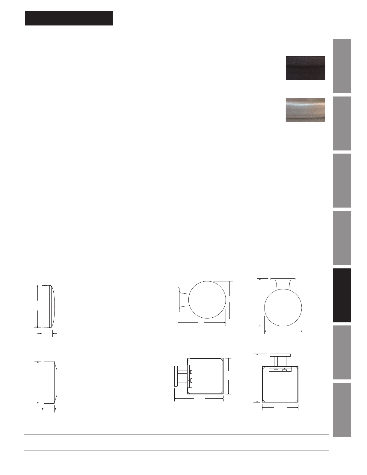
OUTSIDE DIMENSIONS
Round
“A” Dimensions:
1
⁄4" for 10" clocks
11
1
13
⁄4" for 12" clocks
1
16
⁄4" for 15" clocks
“B” Dimensions:
1
2
⁄4" for 10", 12" & 15" clocks
Square (12" only)
“A” Dimensions:
5
12
⁄8"
“B” Dimensions:
1
3
⁄4"
Wall mount round steel
double dial
A
B
Wall mount steel square
double dial mechanical
A
B
double dial
B
A
double dial mechanical
B
A
Double dial mounting requires a 4" square electrical box in
the wall or ceiling.
Specications
Appendix A
Illumination
GlossaryAppendix B LED
© American Time
Page 2 of 2
PS03058 Rev D
29
Page 30
AllSync Plus Clock Specications
AllSync Plus®
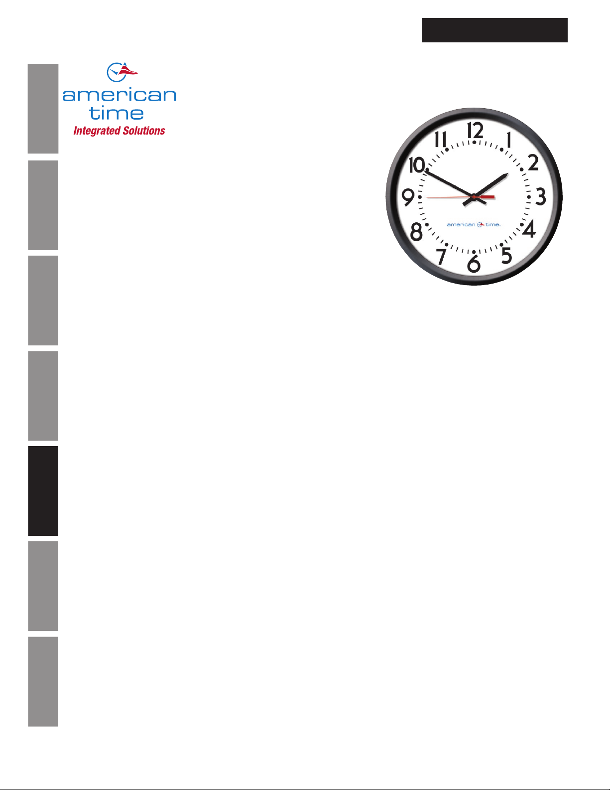
Surface and Double Dial
Molded Case
®
FEATURES
• 5 Year Warranty
• UL Listed - 12" surface mount only
• Microprocessor controlled movement
• 15 minutes of backup power (no batteries required)
• Accuracy to within ±1 second of a master clock
• Reduced power consumption
Installation Introduction
• Attractive modern design
• Impact-resistant black plastic case
• Shatter-resistant polycarbonate crystal
• Diagnostic LED
DESCRIPTION
Operation
The american time™ AllSync Plus clocks are provided in round only high impact black plastic cases with clear
polycarbonate crystals and bold, black numerals and minute markers on a non-yellowing white dial. Stylish hour and minute
hands are aluminum with a black finish and a red sweep hand. Other bezel colors available. Consult factory.
AllSync Plus Clock Installation
& Operation Manual
The american time
programmed to identify the signal it receives from the master and operate as that style of clock. Changing clock operation
from one style to another is as easy as unplugging the clock from one system and plugging it into another. If needed,
changing the placement of 2 small jumpers on the circuit board can change the voltage required to run this clock from
120vac to 24vac or 24vac to 120vac. This clock provides 15 minutes of backup run power without the use of batteries. If a
power outage should last longer than 15 minutes, the clock will synchronize to the master clock at the hourly and 12 hour
correction cycles.
Troubleshooting General
™
AllSync Plus clock is designed to work with multiple master clocks and correction signals. This unit is
Correction Signals
Works on:
• Hourly correction: 7-9 seconds starting at the 57th minute and 54th second. 12 hour correction: 13-18 seconds starting at
5:57:54 (am and pm).
• Hourly correction: 24-28.5 seconds starting at the 0 minute and 0 second. 12 hour correction: 24-32 minutes starting at
Appendix A
6:00:00 (am and pm).
Specications
• *Hourly correction: 54-56 seconds starting at the 58th minute and 5th second. 12 hour correction: 10 pulses of 94-96
seconds starting at 5:05:00 (am and pm) and repeating every 2 minutes.
• Hourly correction: 24-26 seconds starting at 0 minute and 0 second. 12 hour correction: 25 pulses of 24-26 seconds
starting at 6:00:00 (am and pm) and repeating every 60 seconds.
• Hourly correction: 63-67 seconds starting at the 58th minute and 0 second. 12 hour correction: 14 pulses of 63-67
seconds starting at 5:06:00 (am and pm) and repeating every 2 minutes.
• *Hourly correction: 54-56 seconds starting at the 58th minute and 5th second. 12 hour correction: 12 pulses of 63-67
Illumination
seconds starting at 5:05:00 (am and pm) repeating every 90 seconds.
*Note:
When switching between these correction protocols, you must use a different correction protocol to complete the transition.
The AllSync Plus clock needs to distinguish between hourly corrections before it can change correction protocols internally.
Glossary Appendix B LED
140 3rd St. S, PO Box 707, Dassel, MN 55325
800-328-8996 •
30
american-time.com
Page 1 of 2
PS03059 Rev D
© American Time
Page 31
AllSync Plus Clock Installation
Surface
mount plastic
Wall mount plastic
Ceiling mount plastic
Ceiling mount plastic
double dial
A
A
B
& Operation Manual
AllSync Plus Clock Specications
SPECIFICATIONS
• 24vac/60 Hz or 120vac/60 Hz
• Current draw: Single dial:
24vac, 1 watt, .043 amps
120vac, 3 watts, .028 amps
Double dial:
24vac, 2 watts, .086 amps
Maximum operating voltage: 24vac setting = 40vac
120vac setting = 150vac
Minimum operating voltage: 24vac setting = 15vac
120vac setting = 50vac
120vac, 6 watts, .056 amps
GENERAL
Types of secondary clocks compatible with AllSync Plus:
Cincinnati WS*, *D-8, *D-10, *D-12 Series
Dukane 24SS* Series, 240* Series
Edwards *010 & *012 Series
Faraday 2315*, 2316*, 2335*, 2336*, 2370*, 2372*, 2380*, 2382*, 2311*, 2320*, 2331*, 2314*,
1310 through 1431 Series and 2420* through 2431* Series
Honeywell ST402A* Series
Lathem Type SS* Series
National Time *EX-HH and *EX-LL Series
Simplex
®
& IBM 77* Series, 82* Series, 2310 – 92* Series, 6310 – 92* Series
*Indicates more numbers before or after.
ORDERING INFORMATION
Part # Description
U44BAAA904 10" Rd Surface 120vac
U44BABA904 10" Rd Surface 24vac
U54BAAA304 12" Rd Surface 120vac
U54BABA304 12" Rd Surface 24vac
U53BAAA204 12" Rd Double dial wall 120vac
U53BABA204 12" Rd Double dial wall 24vac
U52BAAA204 12" Rd Double dial ceiling 120vac
U52BABA204 12" Rd Double dial ceiling 24vac
Note:
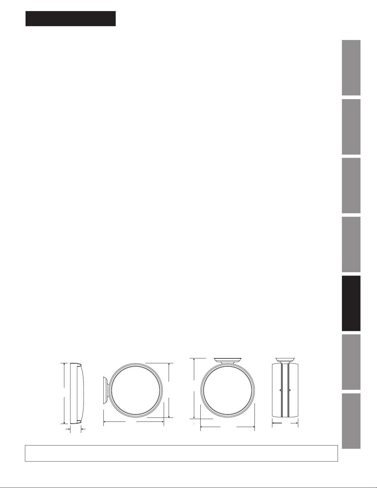
Double dial mounting requires a 4" square electrical box in the wall or ceiling. Surface clocks have a molded in hanger
in the plastic case used to secure the clock to a bracket (pictured below) to a single gang electrical box.
Part # Description
U64BAAA304 15" Rd Surface 120vac
U64BABA304 15" Rd Surface 24vac
U63BAAA204 15" Rd Double dial wall 120vac
U63BABA204 15" Rd Double dial wall 24vac
U62BAAA204 15" Rd Double dial ceiling 120vac
U62BABA204 15" Rd Double dial ceiling 24vac
InstallationIntroduction
Operation
TroubleshootingGeneral
At American Time, we continually strive to improve our products to meet our customers’ needs and to provide the best possible value. The above specifications
are believed to be correct, are subject to change without notice and may otherwise vary from the above. Please call if you need verification of any specifications
or the suitability of a particular product for a particular application.
OUTSIDE DIMENSIONS
Surface
SIZE A B C
10" 10
12" 13
15" 16" 2
3
⁄8" 21⁄2" N/A
1
⁄4" 21⁄2" N/A
1
⁄2" N/A
Note: 12" surface mount
clocks include security
bracket.
Double Dial (12" & 15" only)
12" 13
15" 16" 19
double dial
A
B
B
1
⁄4" 15" 85⁄8"
A
1
/4" 85⁄8"
B
double dial
A
Plastic double
dial prole
C
Specications
Appendix A
Illumination
GlossaryAppendix B LED
© American Time
Page 2 of 2
PS03059 Rev D
31
Page 32
Appendix B - LED Indication
Note: LED indicator can be found on the back of the AllSync Plus clock on the side of the dust cover as indicated
by the decal, or refer to picture on page 19.
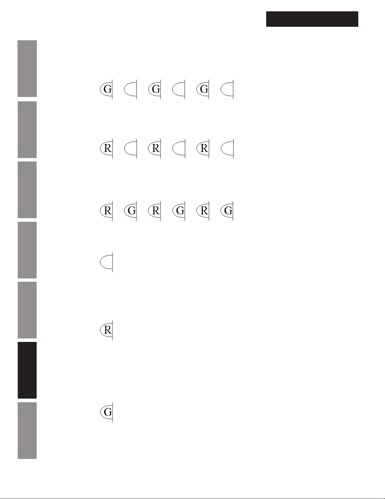
Normal Operation:
Flashing Green (0.5 sec. ON – 0.5 sec OFF) = Microprocessor is sending an update to the movement.
Note: The movement requests the time from the circuit board after startup and at 2am, 8am, 2pm and 8pm as
seen on the clock. During this request the circuit board will send the time to the movement. Each request will last
approximately 3 minutes.
Flashing Red (0.5 sec. ON – 0.5 sec OFF) = Incorrect DIP switch settings or clock error.
Installation Introduction
Note: If the LED is flashing red settings in the clock may be incorrect. Contact American Time Technical support
for assistance at 800-328-8996.
Alternating Red and Green (0.5 sec Red – 0.5 sec. Green) = AllSync Plus circuit board receiving correction
signal from master.
Operation
AllSync Plus Clock Installation
& Operation Manual
Both colors OFF 1 sec. = At the top of each minute the AllSync Plus clock LED will turn off at the 00 sec. and
continue with normal operation at 01 sec.
Troubleshooting General
Note: After the clock has had sufficient time to synchronize (the LED will remain green and the movement has
crossed 8:00 or 2:00 on its face) this LED flashing off should match the second hand on the clock passing the top
of the minute.
Continuous Red = Power is on and the AllSync Plus circuit board has not received a 12 hour correction in last 15
hours.
Appendix A
Specications
Note: If the AllSync Plus clock is installed in a clock system running a correction protocol different than 01
(factory) or its previously recognized protocol, it may require more than one 12 hour correction to adjust its internal
clock. In this case the LED will remain red after one 12 hour correction.
Illumination
Continuous Green = Power is on and the AllSync Plus circuit board has received at least one 12 hour correction
in the last 15 hours.
Glossary Appendix B LED
32
© American Time
Page 33
AllSync Plus Clock Installation
& Operation Manual
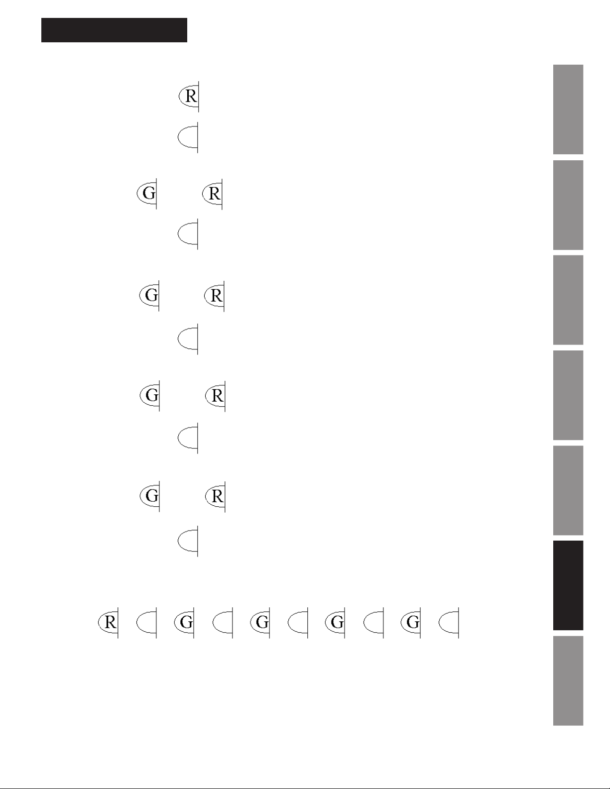
Startup diagnostics routine
1. 5 sec. – solid red only
2. 1 sec. – OFF
Appendix B - LED Indication
3. 1 sec. – Green (DIP Switch 1 ON) or Red (DIP Switch 1 OFF)
Or
4. 1 sec. – OFF
5. 1 sec. – Green (DIP Switch 2 ON) or Red (DIP Switch 2 OFF)
Or
6. 1 sec. – OFF
7. 1 sec. – Green (DIP Switch 3 ON) or Red (DIP Switch 3 OFF)
Or
8. 1 sec. – OFF
9. 1 sec. – Green (DIP Switch 4 ON) or Red (DIP Switch 4 OFF)
InstallationIntroduction
Operation
TroubleshootingGeneral
Specications
Appendix A
Or
10. 2 sec. – OFF
11. Continue with normal operation
Note: For normal operation all DIP switches should be on or green during the startup diagnostics.
Note: If the circuit board has not received power for over 30 minutes it may cycle through the startup diagnostics
several times while the power cell is charging.
© American Time
Illumination
GlossaryAppendix B LED
33
Page 34

Glossary
Clock Protocol - A specific time and duration of a set of correction pulses sent from a master clock to synchronize
a clock system. Through the development of clock systems many different clock system manufacturers designed
their own clock protocols. For this reason clocks cannot generally move from one system to another unless
the system has the same clock protocol. The AllSync Plus clock is designed to recognize many different clock
protocols.
Cold Start - AllSync Plus operational state in which power is applied for the first time or after the clock has not
had power for a sufficient amount of time to drain it to the point it resets its internal processor.
LED - Light Emitting Diode - Indicator light on the back of the AllSync Plus clock.
Master Clock - In a clock system, a device that acts as the source of time. The master clock transmits the time to
any number of secondary (or slave) clocks.
Movement - The inner mechanism of an analog clock that moves the clock’s hands.
Installation Introduction
Secondary Clock - Also known as a slave clock, this is a clock that synchronizes its timekeeping to that of a
connected master clock.
Synchronization - The process of bringing two clocks or time sources into phase so their difference is zero. In
the case of a timekeeping system, time synchronization takes place between the master clock and all secondary
clocks.
AllSync Plus Clock Installation
& Operation Manual
Operation
Troubleshooting General
Appendix A
Specications
Illumination
Glossary Appendix B LED
34
© American Time
 Loading...