


INSTALLATION
INSTRUCTIONS
Townsend
®
Roman Tub Filler
T353900
T353901
Thank you for selecting American Standard...
the benchmark of fine quality for over 140 years.
To ensure that your installation proceeds smoothly-please read
these instructions carefully before you begin.
RECOMMENDED TOOLS
Phillips Screwdriver
ROUGHING-IN
DIMENSIONS
215 mm
(8-1/2")
Flat Blade Screwdriver
253 mm
(10")
198 mm
(8")
116 mm
(5")
Channel Locks
102 mm
(4")
434 mm
(17")
280 mm
(11")
Adjustable Wrench
99 mm
(4")
Certied to comply with ANSI A112.18.1M
Hex Wench
(supplied)
1
INSTALL SPOUT
CAUTION
Turn off hot and cold water
supplies before begining.
• Apply 4-5 drops of THREADLOCKER (1)
on DIVERTER INSERT (2) threads (supplied).
NOTE: If installing on nished deck, install DIVERTER
INSERT (2) through WASHER (7).
• Thread DIVERTER INSERT (2) carefully until it touches the
installation surface, be sure the RUBBER RING (5)
is properly seated in it’s RECESS at the base of the
SPOUT (3).
• Thread SET SCREW (4) using 5 mm hex wrench supplied.
Make certain SET SCREW (4) is properly aligned and tight
so that SPOUT (3) is locked in place.
• Install PLUG BUTTON (6).
1" MAX.
(25 mm)
8" TO 16"
FLEXIBLE INSTALLTION
(203 TO 406 mm)
3
1
6
4
RECESS
5
2
7
Hex wench
(supplied)
MOUNTING
SURFACE
Product names listed herein are trademarks of AS America, Inc.
© AS America, Inc. 2018
- 1 -
M965951 (8/18)
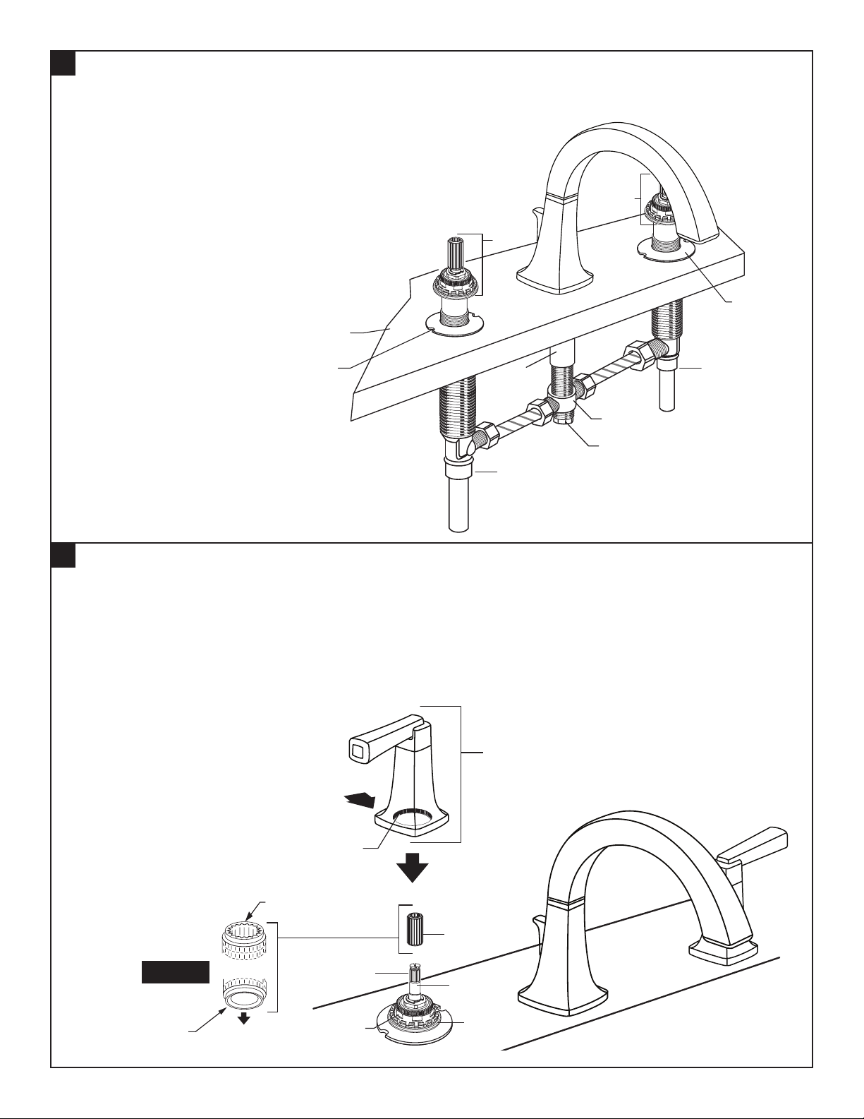
2
VALVE ASSEMBLY
• Remove PLASTER GUARDS.
• Thread INSERT (1) into SIDE VALVE (2) until it touches the
installation surface.
• Thread INSERT (3) into SIDE VALVE (4) until it touches the
installation surface.
• Tighten COUPLING (5) into TEE (6) for products without
hand shower.
FITTING
MOUNTING
DECK
VALVE
LOCKING
HOT
1
SPOUT
SHANK
2
3
VALVE
LOCKING
COLD
4
6
5
3
INSTALL HANDLES
• Turn VALVE to OFF position.
• Push ADAPTER (1) on VALVE STEM (2), so that the hole of the ADAPTER (1) without a spline is facing up. Fig. A.
Tighten STEM SCREW (3) to secure ADAPTER (1).
• Align DECK ADAPTER (5) to LEVER HANDLE ASSEMBLY (4). Thread LEVER HANDLE
ASSEMBLY (4) onto DECK ADAPTER (5) rmly to ush against mounting surface.
4
FEMALE TEETH
TOP
1
Fig. A.
SPLINE END DOWN
MALE TEETH
3
2
5
- 2 -
M965951 (8/18)
 Loading...