

Page 1
Installation
Instructions
SERIN
™
2064.451
WALL MOUNT FAUCET
IN-WALL LAVATORY FITTING
Thank you for selecting American-Standard...
the benchmark of fine quality for over 100 years.
To ensure that your installation proceeds smoothly-please read these instructions carefully before you begin.
To ensure that your installation proceeds smoothly-please read these instructions carefully before you begin.
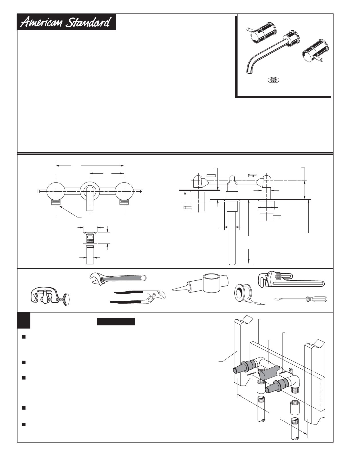
ROUGHING-IN DIMENSIONS
8"
(203mm)
CROSS
HANDLE
HOT
1/2" NPT INLETS
2-1/8" D.
(54mm)
4"
(102mm)
COLD
2" MAX. (51mm) MAX.
FINISHED
WALL
2" MIN.
(51mm)
2" D.
(52mm)
Certified to comply with ASME A112.18.1M
U.S. Patent No. 5,819,789
M968852 Rev.1.3
3" MAX.
(76mm) MAX.
1"
(25mm)
2" D.
(52mm)
FINISHED
9-1/4"
WALL
(235mm)
1-1/4" O.D.
(32mm) O.D.
Required Tools
Adjustable Wrench
Tubing Cutter
INSTALL VALVE BODY
1
CAUTION
Channel Locks
Turn off hot and cold water
supplies before beginning.
Determine where the finished wall location will be. This measurement
is very important! Note: The rough-in measurement from the finished
wall is; 2" minimum and 3" maximum. This is a 1" tolerance. See
rough-in illustration above.
Secure FAUCET BODY (1) to cross brace of wall structure
at required height using two wood screws.
Connect HOT water supply to left VALVE inlet and COLD water
supply to right VALVE inlet. Use pipe sealant or Teflon tape for
all threaded connections. For sweat connections, do not make
sweat connections directly to valve body. Damage to seals and
and valve cartridge may occur.
Turn valves to off position. Turn hot and cold supplies on and
check fitting connections for leaks .
Complete wall construction.
Plumbers' Putty or
Caulking
WALL STUDS
Teflon Tape
M
A
X
W
A
L
L
M
I
N
1
-
5
/
8
"
D
E
E
P
HOT
Pipe Wrench
Flat Blade Screwdriver
CROSS BRACE
1
WOOD SCREWS
M
A
X
W
A
L
L
M
I
N
1
-
5
/
8
"
D
E
P
E
16"
COLD
Page 2
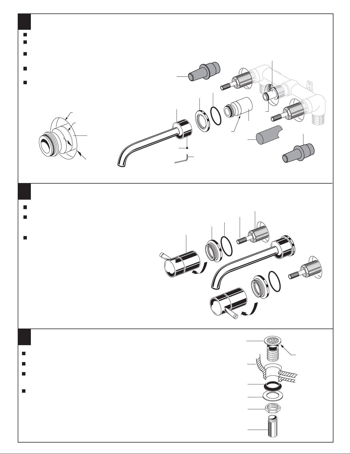
INSTALL WALL SPOUT
2
Remove PLASTER GUARDS (1) from valve bodies.
Inspect that SPOUT NIPPLE O-RING (2) is seated in groove of SPOUT NIPPLE (3).
Thread SPOUT MOUNT (4) onto SPOUT NIPPLE (3). Align groove on SPOUT MOUNT (4)
with face of finished wall. See Figure A.
Install SEAL (5) into SPOUT ESCUTCHEON (6). Place SPOUT
ESCUTCHEON (6) with SEAL (5) onto SPOUT MOUNT (4).
1
Push SPOUT (7) onto SPOUT MOUNT (4). Align SPOUT (7)
and tighten SPOUT SET SCREW (8) with 3mm HEX WRENCH
(9) supplied.
Figure A
7
FINISHED WALL
GROOVE
6
4
8
9
INSTALL HANDLES
3
Turn VALVE STEMS (1) to off position.
Place O-RING (2) into HANDLE ESCUTCHEON (3).
Thread HANDLE ESCUTCHEON (4) onto VALVE (5) until
snug against finished wall.
Thread HANDLE BASE (4) onto HANDLE ESCUTCHEON (3)
until seated tightly against HANDLE ESCUTCHEON (3).
4
M
I
N
1
M
A
-
5
/
8
"
X
W
A
L
L
D
E
E
P
5
GROOVE
3
3
2
4
1
1
M
A
X
W
A
L
M
I
N
1
-
5
E
/
8
D
"
5
1
2
DRAIN INSTALLATION
4
Apply a bead of PUTTY to underside of FLANGE on DRAIN BODY (1).
Feed DRAIN BODY (1) down through lavatory.
Assembly GASKET (2) WASHER (3) and LOCKNUT (4) onto DRAIN BODY (1).
Tighten LOCKNUT (4) firmly.
Assembly TAILPIECE (5) to DRAIN BODY (1).
1
PUTTY
LAVATORY
2
3
4
5
M968852 Rev.1.3
Page 3

5
SERVICE
To change direction of handle rotation,
proceed as follows:
Turn valve to OFF position.
Thread counter-clock wise HANDLE BASE (1) to remove
HANDLE ASSEMBLY (2) from ESCUTCHEON BASE (3).
Use a flat blade screw driver to remove SPRING CLIP (4).
Lift STOP WASHER (5), turn 90˚ and replace.
Replace SPRING CLIP (4).
Reinstall HANDLE ASSEMBLY (2).
If spout drips, operate handles several times from OFF to ON
position. Do not force - handles turn only 90˚.
TEST INSTALLED FAUCET
6
1
2
TO REMOVE
HANDLE
3
4
90˚
5
Turn HANDLES to "off" position.
Remove AERATOR (1) using TOOL (2) supplied.
Turn hot and cold water supplies on. Operate
both HANDLES to flush water lines thoroughly.
Check spout connections for leaks.
Check all drain connections for leaks.
Turn handles to OFF position. Replace AERATOR (1).
1
2
CARE INSTRUCTIONS:
7
DO: SIMPLY RINSE THE PRODUCT CLEAN WITH CLEAR WATER. DRY WITH A SOFT COTTON FLANNEL CLOTH.
DO NOT: DO NOT CLEAN THE PRODUCT WITH SOAPS, ACID, POLISH, ABRASIVES, HARSH CLEANERS, OR A
CLOTH WITH A COARSE SURFACE.
M968852 Rev.1.3
Page 4

M962422-YYY0A
SPOUT ASSEMBLY
M962757-0070A
AERATOR
M962423-YYY0A
SPOUT ESCUTCHEON KIT
M962352-0070A
SPOUT MOUNTING KIT
SERIN
™
WALL MOUNT
LAVATORY FAUCET
MODEL NUMBER
2064.451
994053-0070A
CARTRIDGE
617852-0070A
ADAPTER
918555-0070A
HANDLE SCREW
Replace the "YYY" with
appropriate finish code
CHROME
SATIN NICKEL
002
295
621423-0070A
VALVE HOUSING
M962424-YYY0A
HANDLE ESCUTCHEON KIT
M950245-YYY0A
HANDLE ASSEMBLY
015025-YYY0A
DRAIN COMPLETE
070532-0040A
TAILPIECE
For toll-free information and answers to your questions, call:
IN CANADA 1-800-387-0369 (TORONTO 1-905-306-1093)
Product names listed herein are trademarks of American Standard Inc.
© AS America, Inc. 2008
HOT LINE FOR HELP
1 (800) 442-1902
Weekdays 8:00 a.m. to 6:00 p.m. EST
Weekdays 8:00 a.m. to 7:00 p.m. EST
IN MEXICO 01-800-839-12-00
M968852 Rev.1.3
 Loading...