

Page 1
INLETS
4-1/16"
INLETS
INSTALLATION
INSTRUCTIONS
TOWNSEND
®
BATH AND SHOWER
TRIM KIT
Thank you for selecting American Standard...
the benchmark of fine quality for over 100 years.
To ensure that your installation proceeds smoothly-please
read these instructions carefully before you begin.
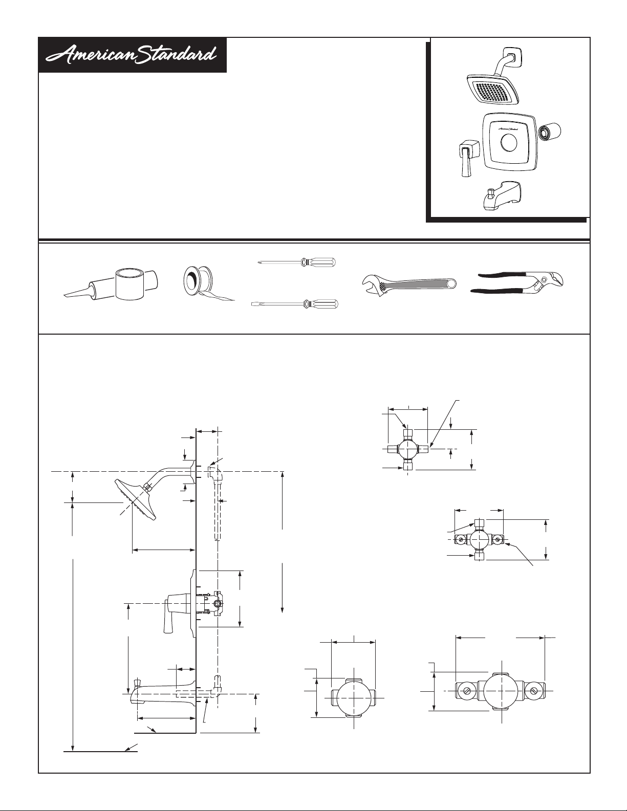
RECOMMENDED TOOLS
Phillips Screwdriver
Plumbers’ Putty
or Caulking
ROUGHING-IN DIMENSIONS
• To assure proper positioning in relation to wall.
Note roughing-in dimensions.
Teon Tape
Flat Blade Screwdriver
T353.500
T353.501
T353.502
T353.507
T353.508
Certied to comply with ANSI A112.18.1M
Adjustable Wrench Channel Locks
3.3/8" (85 mm) REF.
74" (1880 mm)
FOR HEAD
CLEARANCE
TOP OF TUB RIM
FINISHED WALL
18" (457 mm)
OPTIONAL
BOTTOM OF TUB
2-9/16"
(65 mm)
7" (177 mm) REF.
1-1/2" REF.
(38 mm)
6.5" REF.
(165 mm)
1-5/8" TO 3-1/4"
(41 TO 83 mm)
1/2" (12 mm) NPT
1-5/8" TO 3-1/4"
(41 TO 83 mm)
7-1/4"
(184 mm)
1/2" (13 mm)
COPPER
OPTIONAL TO FINISHED
FLOOR USUALLY
BETWEEN 65'' AND 80''
(1651 AND 2032 mm)
3-3/8"
(86 mm)
3-3/8"
(86 mm)
OUTLETS
1/2" NPT
(13 mm)
4"
(102 mm)
SHR. 1/2" (13 mm) NOM.
COPPER SWEAT
SWEAT
INLETS
TUB 1/2" (13 mm) NOM.
COPPER SWEAT
SHR. 1/2" (13 mm) NOM.
TUB 1/2" (13 mm) NOM.
INLETS 1/2" NPT
(13 mm)
THREADED INLETS
(103 mm)
COPPER SWEAT
COPPER SWEAT
OUTLETS
1/2" NPT
(13 mm)
3-3/8"
(86 mm)
1/2" (13 mm) NOM.
COPPER SWEAT
2"
(51 mm)
4-1/16"
(103 mm)
SWEAT
INLETS (STOPS)
5-7/8"
(149 mm)
4-1/16"
(103 mm)
INLETS
1/2" (13 mm) NOM.
COPPER SWEAT
5-7/8"
(149 mm)
THREADED INLETS (STOPS)
INLETS
1/2" NPT
(13 mm)
Product names listed herein are trademarks of AS America, Inc.
© AS America, Inc. 2016
- 1 -
M965724 Rev. 1.0 (7/16)
Page 2
1
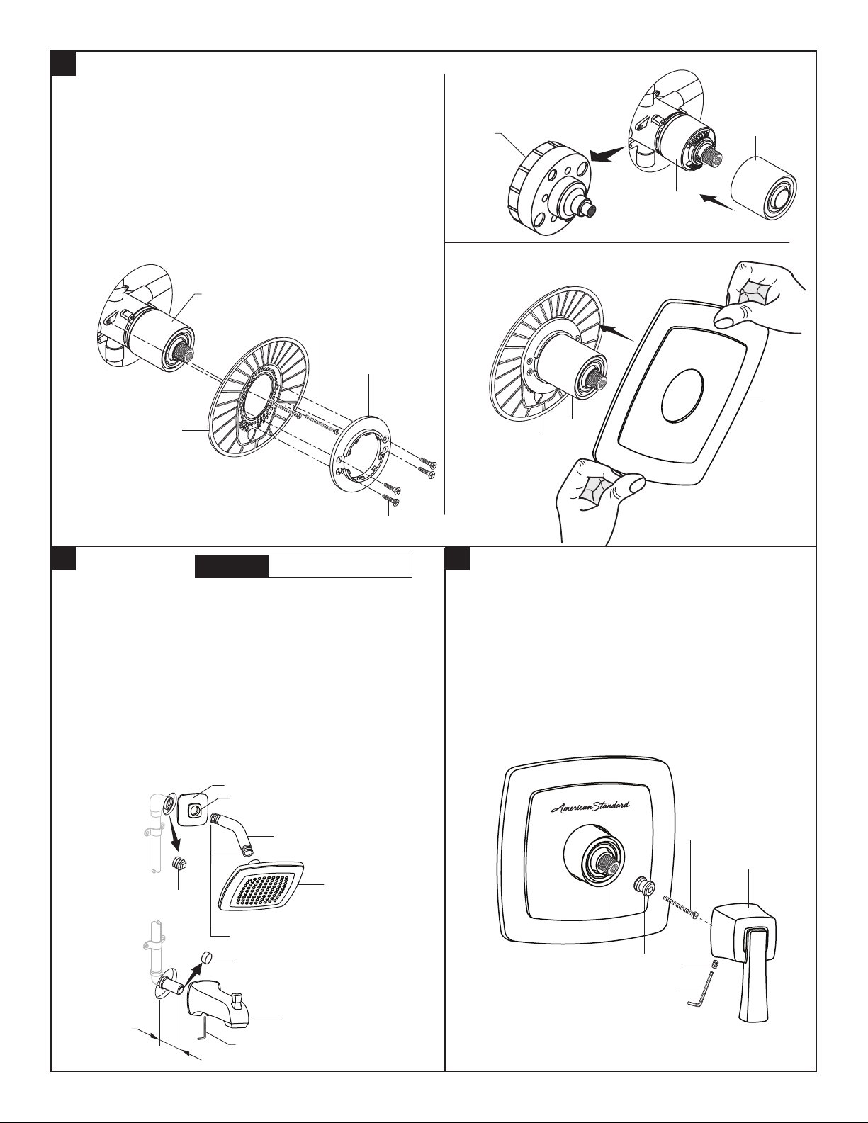
INSTALL VALVE TRIM
• Figure 1. Remove plaster guard from valve. Push CAP (1)
over VALVE CARTRIDGE (2) until seated against stop.
• Figure 2. Push ESCUTCHEON HOLDER (3) onto CAP (1)
and attach to valve body with LONG SCREWS (4). Mount
ESCUTCHEON SUPPORT (5) to ESCUTCHEON HOLDER
(3) with 4 SHORT SCREWS (6).
• Figure 3. Install ESCUTCHEON (7) onto CAP (1) and push
ush against nished wall. Escutcheon (7) will snap t onto
ESCUTCHEON SUPPORT (5).
1
4
5
PLASTER
GUARD
Figure 1.
1
2
7
3
Figure 2.
2
INSTALL TRIM
Note: Apply sealant or Teflon Tape to shower arm.
• Remove PIPE PLUG and CAP (1, 2) from shower pipe
and tub ller pipe.
• Install SHOWER ESCUTCHEON (3) onto SHOWER ARM
(4). Apply sealant or Teon tape to threads on both ends
of SHOWER ARM (4) and thread longer leg of SHOWER
ARM (4) into shower elbow.
• Thread SHOWER HEAD (5) onto SHOWER ARM (4).
Install TUB SPOUT (6). Tighten with HEX WRENCH
supplied. Important: Do not over tighten Set Screw.
CAUTION
Protect finish on SHOWER HEAD
and TUB SPOUT when installing.
3
O-RING
4
1
5
Figure 3.
6
3
INSTALL HANDLE
• Hold ADAPTER (1) onto VALVE STEM (2) and install
ADAPTER SCREW (3) through ADAPTER (1) into
VALVE STEM (2).Tighten ADAPTER SCREW (3) to
secure ADAPTER (1) to VALVE STEM (2).
• Install HANDLE BASE (4) onto ADAPTER (1). Insert
SET SCREW (5) into HANDLE BASE (4). Align
HANDLE BASE (4) and tighten with HEX WRENCH (6)
supplied.
3
1-1/2"
4
5
1
APPLY SEALANT OR
TEFLON TAPE TO THREADS
2
2
5
1
6
6
HEX WRENCH
- 2 -
M965724 Rev. 1.0 (7/16)
Page 3
4
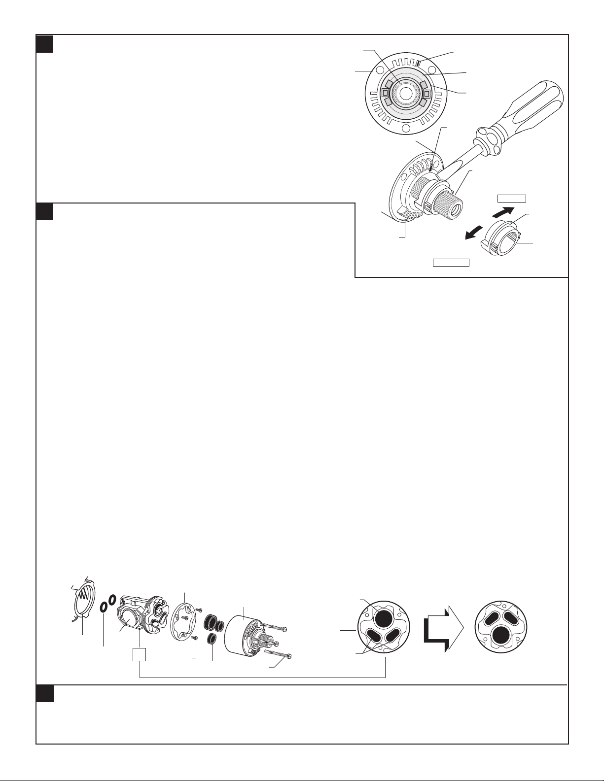
ADJUST HOT LIMIT STOP
• By restricting HANDLE rotation and limiting the amount of hot water
2
7
9
5
1
3
1
1
3
0
1
4
5
1
3
5
allowed to mix with the cold, the HOT LIMIT SAFETY STOP (1)
reduces risk of accidental scalding. To set the maximum hot water
1
temperature of your faucet, all you need to do is adjust the setting on
the HOT LIMIT SAFETY STOP (1).
• T u r n CARTRIDGE STEM (2) to the OFF position (coldest setting) before
3
making adjustment to HOT LIMIT STOP (1). Use a at blade screwdriver
to pry free the HOT LIMIT SAFETY STOP (1). Pull forward and rotate
counterclockwise one number to limit hot water temperature.
Use ARROW (3) on CARTRIDGE (4) and NUMBERS (5) on HOT LIMIT
STOP (1) for indication.
5
TO GAIN ACCESS TO VALVE FOR SERVICING
• Remove HANDLE (see step 3 and reverse).
• Remove ESCUTCHEON and CARTRIDGE CAP (see step 1 and re-
verse).Shut off water supply by either closing off main water supply, or
7
5
3
1
4
COLDER
(Larger Numbers)
0 1 3 5 7 9 11 13 15
1
5
1
3
1
1
9
2
5
3
1
closing off the hot and cold CHECK STOPS on valve.
VALVE LEAKS WHEN SHUT OFF
• Remove CARTRIDGE (1) by removing CARTRIDGE SCREWS (2). Remove three SCREWS (3) from FIXATION RING (4)
and pull out PRESSURE BALANCING (5) unit.
• Clean SEALS (9) on base of CARTRIDGE (1). Check base of PRESSURE BALANCING UNIT (5) and clean O-RINGS (6).
Remove CAPS (7) and check O-RINGS on inside of CAPS (7). Clean inside sealing surfaces of VALVE BODY (8).
• Re-assemble PRESSURE BALANCING UNIT (5) and CARTRIDGE (1). Tighten all screws. Turn on water supply and see
above for installing TRIM and HANDLE.
HOTTER
(Smaller Numbers)
0 1 3 5 7 9 11 13 15
5
1
5
1
3
1
1
9
7
1
UNABLE TO MAINTAIN CONSTANT TEMPERATURE
• Remove PRESSURE BALANCE UNIT (5).
• Remove CAPS (7) and clean valve thoroughly.
• Examine balancing unit and check condition of O-ring on end of piston. Piston should move back and forth.
Order Repair Part M952100-0070A if balancing unit is defective.
• Replace CAPS (7) and install PRESSURE BALANCE UNIT (5). Make sure inlets line up with two holes in bottom of casting.
Top ange should butt-up against top of casting.
BACK TO BACK INSTALLATION
• Remove PRESSURE BALANCE UNIT (5). Rotate PRESSURE BALANCE UNIT (5) 180˚ so that the inlets face up and the large
outlet port faces down.
• Push PRESSURE BALANCE UNIT (5) in casting make sure inlets line up with holes in bottom of casting. Top ange should
butt up against top of casting.
• Reassemble FIXATION RING (4) and CARTRIDGE (1).
4
1
8
7
6
5
3
9
2
LARGE OUTLET
5
INLETS
ROTATE 180˚
BACK TO BACK INSTALLATION
6
CARE INSTRUCTIONS:
DO: SIMPLY RINSE THE PRODUCT CLEAN WITH CLEAR WATER. DRY WITH A SOFT COTTON FLANNEL CLOTH.
DO NOT: DO NOT CLEAN THE PRODUCT WITH SOAPS, ACID, POLISH, ABRASIVES, HARSH CLEANERS, OR A
CLOTH WITH A COARSE SURFACE.
- 3 -
M965724 Rev. 1.0 (7/16)
Page 4
TOWNSEND
®
BATH AND SHOWER
TRIM KIT
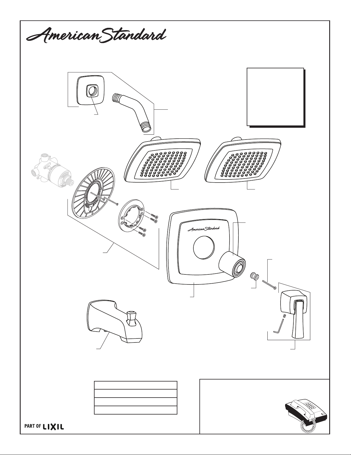
MODEL NUMBERS
T353.500
T353.501
T353.502
A912654-0070A
O-RING
M962642-0070A
ESCUTCHEON HOLDER
M970050-YYY0A
SHOWER ARM & FLANGE
1660508.YYY
SHOWER HEAD
2.5 GPM
T353.507
T353.508
1660509.YYY
SHOWER HEAD
1.75 GPM
M907053-YYY0A
CARTRIDGE CAP
A918477-0070A
HANDLE SCREW
8888093-YYY
DIVERTER SPOUT
(SLIP-ON)
M907837-YYY0A
ESCUTCHEON
Replace the “YYY” with
appropriate finish code
POLISHED CHROME 002
SATIN NICKEL 295
LEGACY BRONZE 278
POLISH NICKEL 013
- 4 -- 4 -
M918039-0070A
HANDLE ADAPTER
M970051-YYY0A
HANDLE KIT
HOT LINE FOR HELP
For toll-free information and answers to your questions, call:
1 (800) 442-1902
Mon. - Fri. 8:00 a.m. to 8:00 p.m. EST
Saturday 10:00 a.m. to 4:00 p.m. EST
IN CANADA 1-800-387-0369
(TORONTO 1-905-306-1093)
Weekdays 8:00 a.m. to 7:00 p.m. EST
IN MEXICO 01-800-839-1200
M965724 Rev. 1.0 (7/16)
 Loading...