

Page 1
Installation Instructions
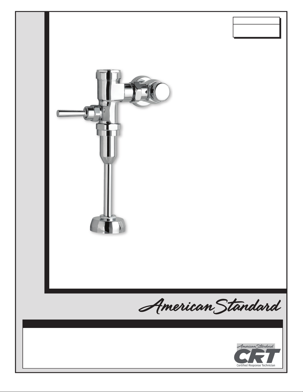
Ultima™ Manual
Urinal Flush Valve, Piston-Type
1-1/4" Top Spud, 1.0 gpf
MODEL NUMBERS
6045.601
OPERATING PRESSURE:
• Overall Range: 20-125 psi **
• 25 psi (flowing) - 80 psi (static)
FLOW REQUIREMENT:
• 10gpm (37.9 L/min).
**Water pressure over 80 psi is not recommended with most
plumbing fixtures
Certified to comply with:
• ASSE 1037
• ANSI/ASME A112.19.2
• ADA Compliant
© 2019 AS America, Inc.
Installation Instructions
t
NOTE TO INSTALLER: Please give this manual to the customer after installation.NOTE TO INSTALLER: Please give this manual to the customer after installation.
To learn more about American Standard Selectronic® Products visit our website at: www.americanstandard-us.com
or e-mail us at: [email protected]
For Parts, Service, Warranty or other Assistance,
please call (844) CRT-TEAM / (844) 278-8326 (In Canada: 1-800-387-0369)
(In Toronto Area only: 1-905-306-1093)
Page 2
Thank you for selecting American-Standard...the benchmark of fine quality for over 100 years. To ensure that your
In s ta l la t io n I n st r u ct i on s
installation proceeds smoothly--please read these instructions carefully before you begin.
UNPACKING
All American Standard Products Are Water Tested At Our Factory.
Some Residual Water May Remain In The Valve During Shipping.
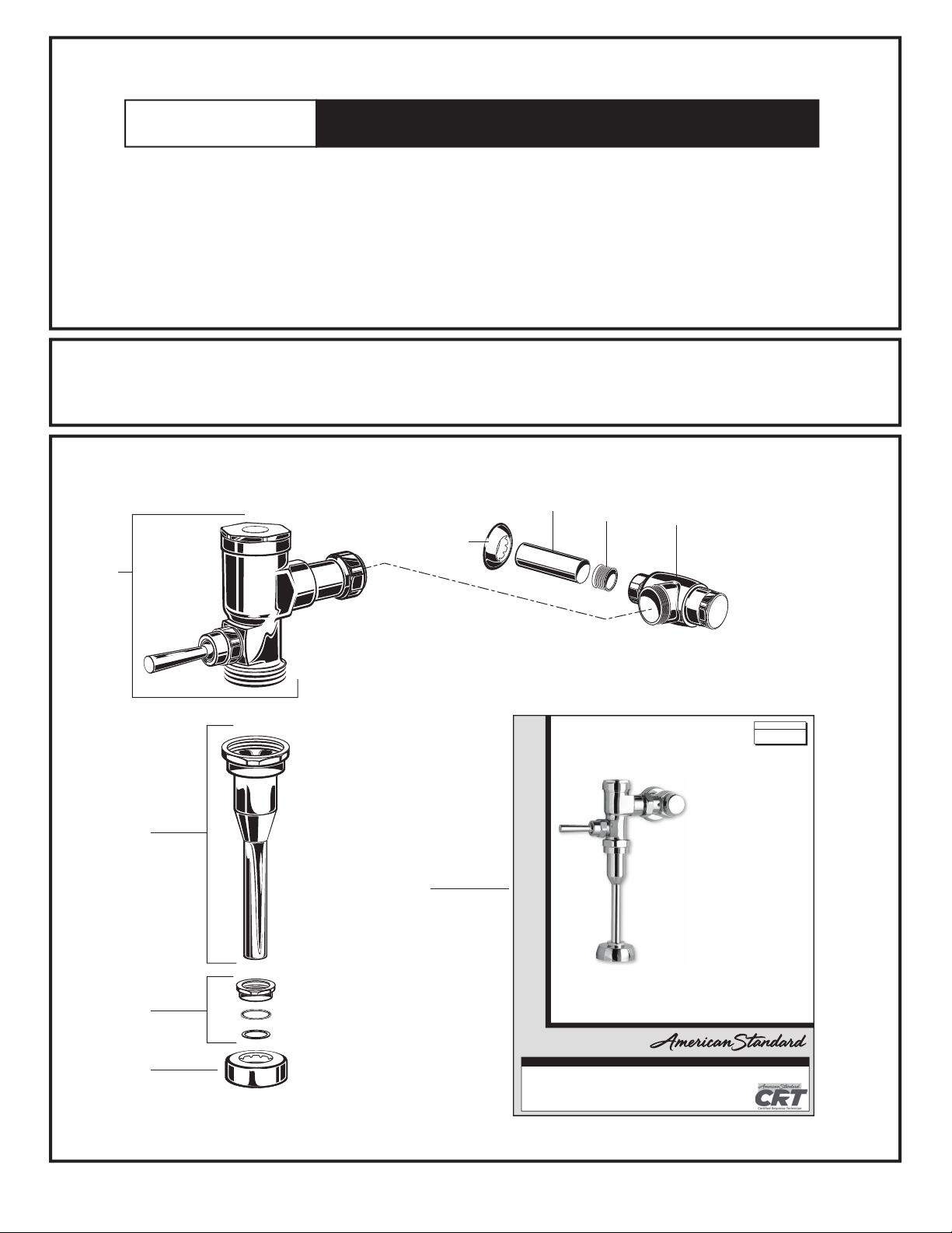
Remove the Flush Valve items from the carton. The illustration below shows all items after
they have been removed from the carton. Some items may be packaged partially assembled to
other items.
1. Flush Valve Assembly
2. Down Tube and Vacuum Breaker
3. Spud Coupling Nut and Washers
4. Spud Flange
5. Sweat Solder Adapter
6. Cover Tube
7. Wall Escutcheon
8. Supply Stop
9. Installation Instructions
CARE INSTRUCTIONS:
DO: CLEAN WITH CLEAR WATER. DRY WITH A SOFT COTTON FLANNEL CLOTH.
DO NOT: DO NOT CLEAN THE PRODUCT WITH SOAPS, ACID, POLISH, ABRASIVES, HARSH CLEANERS, OR A
CLOTH WITH A COARSE SURFACE.
6
5
8
7
1
Ultima™ Manual
Urinal Flush Valve, Piston-Type
1-1/4" Top Spud, 1.0 gpf
MODEL NUMBERS
6045.601
2
9
Certified to comply with:
• ASSE 1037
• ANSI/ASME A112.19.2
• ADA Compliant
3
© 2019 AS America, Inc.
Installation Instructions
M965364 REV. 1.7 (5/19)
OPERATING PRESSURE:
• 25 psi (flowing) - 80 psi (static)
FLOW REQUIREMENT:
• 10gpm (37.9 L/min).
**Water pressure over 80 psi is not recommended with most
plumbing fixtures
NOTE TO INSTALLER: Please give this manual to the customer after installation.NOTE TO INSTALLER: Please give this manual to the customer after installation.
4
1
To learn more about American Standard Selectronic® Products visit our website at: www.americanstandard-us.com
or e-mail us at: [email protected]
For Parts, Service, Warranty or other Assistance,
please call (844) CRT-TEAM / (844) 278-8326 (In Canada: 1-800-387-0369)
(In Toronto Area only: 1-905-306-1093)
M965364 REV. 1.7 (5/19)
Page 3
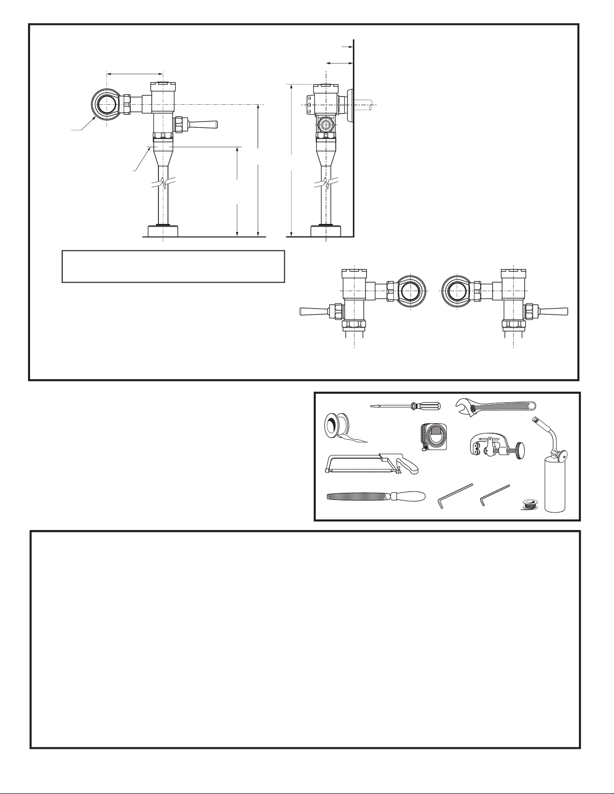
Fig. 1
Roughing-in Dimensions
108mm-133mm
(4-1/4" to 5-1/4")
SUPPLY
DN 32mm
(1" I.P.S.)
*CRITICAL
LEVEL
-C-L-
3/4" VACUUKM
BREAKER SHOWN
152mm
(6)
(Min.)
295mm
(11-1/2")
FINISHED WALL
38mm-127mm
(1-1/2-5")
135mm
(13-1/2")
-C-L-
GENERAL DESCRIPTION:
MANUAL FLUSH VALVE, 1.0 GPF
Exposed Flushometer
for 1-1/4" Top Spud Fixtures
Exclusive, self cleaning piston-operated
flush valve.
OPERATING PRESSURE:
Overall Range: 20-125 psi **
Recommended: 20 psi (flowing)80 psi (static)
FLOW REQUIREMENT:
10gpm (37.9 L/min).
**Water pressure over 80 psi is not
recommended with most
plumbing fixtures
*Note: The Critical Line (-C-L-) on Vacuum Breaker
must typically be 6
Consult Codes for details.
" (152mm) minumim above fixture.
RECOMMENDED TOOLS; Fig. 2
1.
Teflon Tape
2.
Flat Blade Screwdriver (For adjusting Supply Stop)
3.
Adjustable Wrench
4.
Tape Measure
5.
Hacksaw
6.
Tubing Cutter
7.
File
8.
For Sweat Connection; Solder and Torch
9.
2.5mm Hex Wrench
10.
1.5mm Hex Wrench
Fig. 2
Right or Left Hand Installation
See (Section 8) for converting Flush
Valve to Left Hand Installation.
1
2
10'
4
3
6
5
8
7910
PRIOR TO INSTALLATION
Note: Prior to installing the Selectronic™Flush Valve
the following items must be installed.
1. Urinal
2. Drain line
3. Water supply line
IMPORTANT:
• All plumbing must be installed in accordance with
applicable codes and regulations.
• The use of water hammer arrestors is strongly
recommended for commercial applications. All piping
behind the walls should be properly secured and
fastened.
• Water supply lines must be sized to provide an
adequate volume of water for each fixture.
• Flush all water lines prior to operation (See Step 5). Dirt
and debris can cause flush valve to run continuously.
• With the exception of Supply Stop Inlet, DO NOT use
pipe sealant or plumbing grease on any valve component
or coupling!
• Protect the chrome or special finish on the Flushometer.
DO NOT USE toothed tools on finished surfaces to install
or service these valves. Also see “Care and Cleaning”
section of this manual.
• This product contains mechanical and/or electrical
components that are subject to normal wear. These
components should be checked on a regular basis and
replaced as needed to maintain the valve’s performance.
M965364 REV. 1.7 (5/19)
2
Page 4
INSTALL SWEAT SOLDER
1
ADAPTER; Fig. 3
CAUTION
Note: Install Optional Sweat Solder Adapter
(Supplied) for copper pipe supply line. Fig. 3.
Turn water supplies off
before beginning
Fig.3
Fig.3a
FINISHED WALL
A
CENTER LINE OF
FIXTURE SPUD
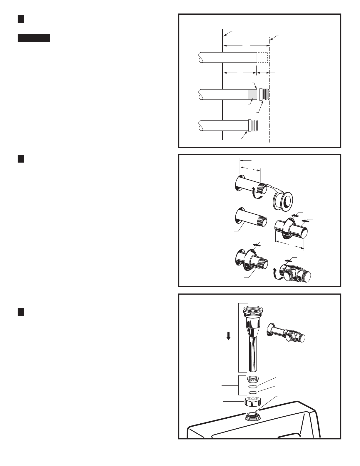
1. Measure the distance (A) from the finished wall to the
center of the inlet spud on the fixture.
2. Cut the supply pipe 1-1/4" (A-B=C) shorter then the
measurement taken in Step 1. File any rough edges off
the end of the supply pipe.
3. Clean the end of the supply pipe. Push the threaded
Adapter on until it is seated against the internal stop.
Sweat the Adapter to the pipe.
INSTALL COVER TUBE, WALL
2
ESCUTCHEON and SUPPLY STOP;
Fig. 4
1. Measure from finished wall to first thread of Adapter
or threaded supply pipe (dimension “X”). Cut COVER
TUBE (1) to length (X). Apply Teflon Tape to the
threaded end of the Adapter or supply pipe. Fig. 4a.
2. Push the COVER TUBE (1) into the WALL
ESCUTCHEON (2). Slide both onto the SUPPLY PIPE
(3). Fig. 4b.
3. Push the COVER TUBE (1) in to expose the threads
of the supply pipe. Fig. 4c. With a wrench thread the
SUPPLY STOP (4) onto the SUPPLY PIPE (3). Align
and tighten. Fig. 4c.
4. Pull COVER TUBE (1) against SUPPLY STOP (4)
and push WALL ESCUTCHEON (2) against finished
wall.
Fig. 4
Fig. 5
Fig. 4a
Fig. 4b
Fig. 4c
(A-B)=
C
FILE EDGES
CLEAN
ADAPTER
SOLDER
ADAPTER
3
1
B
FINISHED WALL
X
2
32mm
(1-1/4)
TEFLON TAPE
2
1
X
4
INSTALL DOWN TUBE AND
3
VACUUM BREAKER; Fig. 5
1. Place the SPUD FLANGE (1) over the spud on the
Fixture.
2. Thread SPUD COUPLING NUT (2) onto Spud. Make
sure SEAL WASHER (3) and FRICTION WASHER (4)
are installed. Do not tighten fully.
3. Insert the DOWN TUBE (5) into the SPUD
COUPLING NUT (2) and push it down.
Note: If cutting Down Tube (5) to size, note that
Critical Line (C/L) on Vacuum Breaker must
typically be 6" (152mm) minumim above fixture.
Consult Code for details.
5
3
2
4
1-1/4" TOP SPUD
1
3
M965364 REV. 1.7 (5/19)
Page 5
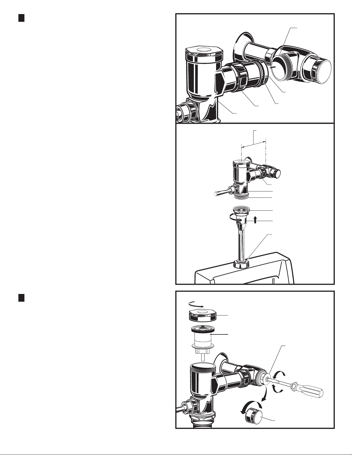
INSTALL FLUSH VALVE;
4
Fig. 6a & 6b
1. As shown in Fig. 6a, insert the side INLET FLANGE (1)
on the FLUSH VALVE (2) into the SUPPLY STOP (3).
Lubricate the INLET FLANGE O-RING (4) with water if
necessary. Lightly tighten COUPLING NUT (5). Fig. 6a.
Important: Do not use lubricants (other than water)
or any type of thread sealing paste or tape.
2. Align the FLUSH VALVE (2) (Fig. 6b) directly above
the DOWN TUBE (7) and VACUUM BREAKER
COUPLING NUT (6).
Note: There is a 13mm, ( 1/2) tolerance for the
121mm (4-3/4) dimension. Fig. 6b.
3. Pull the DOWN TUBE (7) up to meet the threaded
FLUSH VALVE CONNECTION (8) and hand tighten
the VACUUM BREAKER COUPLING NUT (6). Align all
components of the flush valve assembly. Fig. 6b.
4. Lightly tighten the COUPLING NUT (5) connection
first, then the VACUUM BREAKER COUPLING NUT
(6) and finally the SPUD COUPLING NUT (9). Once
alligned correctly, use a wrench to tighten couplings to
make water tight connections. Fig. 6b.
+
–
+
–
Fig. 6a
Fig. 6b
3
1
5
4
2
+
121mm, 13mm
–
+
(4-3/4)( 1/2)
–
5
2
8
FLUSH OUT SUPPLY LINES; Fig. 7
5
1. Remove COVER (1) from SUPPLY STOP (2). Make
sure supply stop is closed.
2. Remove FLUSH VALVE CAP (3). Pull out PISTON (4).
Replace FLUSH VALVE CAP (3) and tighten.
2. With a flat blade screwdriver open SUPPLY STOP (2).
to flush line of any debris or sediment.
4. Close SUPPLY STOP (2). Remove FLUSH VALVE
CAP (3). Replace PISTON (4). Replace FLUSH VALVE
CAP (3) and tighten.
Fig. 7
6
7
9
3
4
2
COUNTER-CLOCKWISE
OPENS CONTROL STOP
REMOVE COVER
CLOCKWISE
CLOSES CONTROL STOP
1
4
M965364 REV. 1.7 (5/19)
Page 6
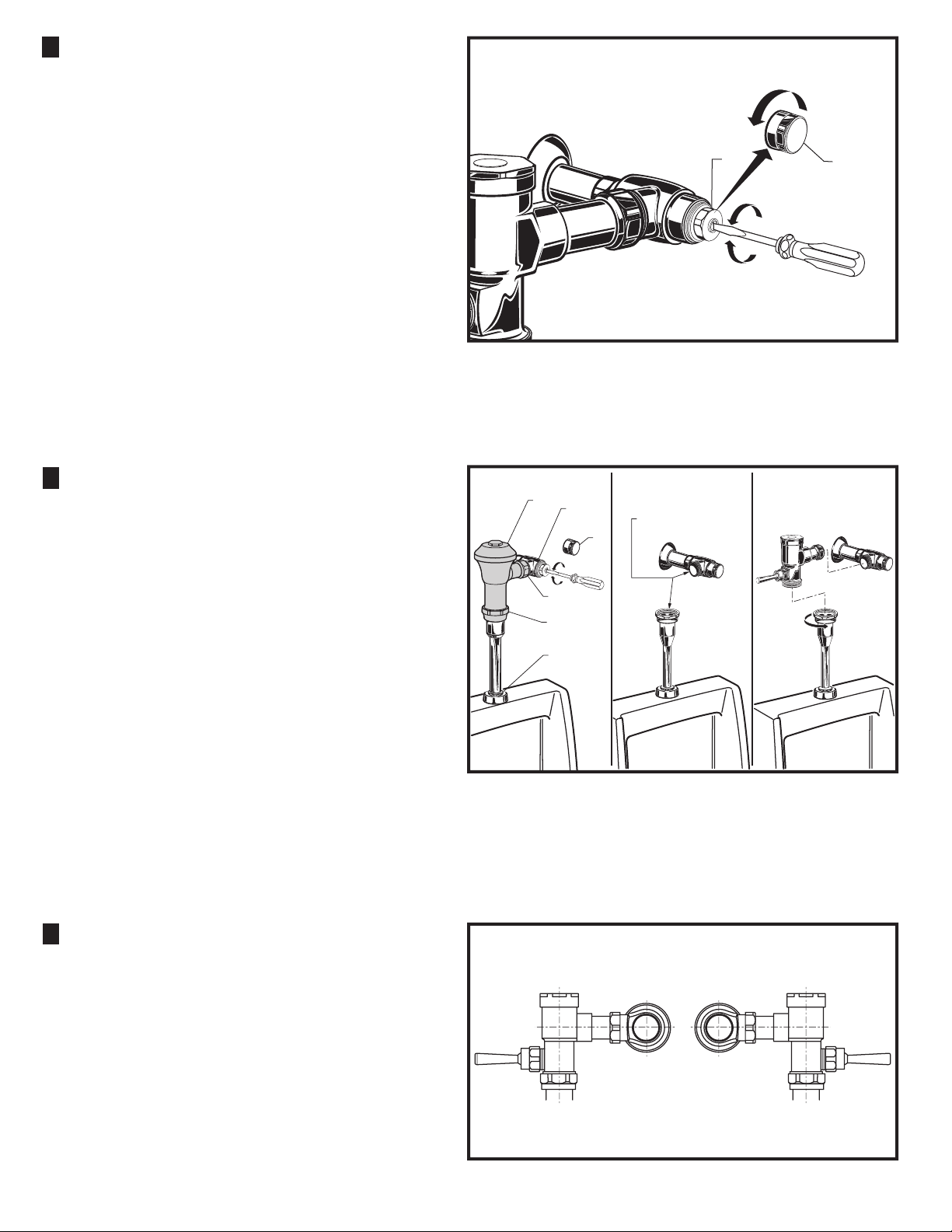
6
ADJUST SUPPLY STOP; Fig. 8
IMPORTANT: To avoid overflowing, the SUPPLY STOP
(3) must never be opened to the point where the flow
from the valve exceeds the flow capacity of the
fixture. The fixture and drain must be able to handle a
continuous flow in case of a flush valve failure.
Valve is designed to provide stated flush volume with
a 10 GPM flow rate.
1. Remove COVER (2) from SUPPLY STOP (3).Turn on
water supply 1/4 turn to 1/2 turn(CCW) and test for leaks.
Note: Unit may flush for approximately 5 to 10 sec.
when water is first turned on.
2. Actuate the FLUSH VALVE by pulling handle down.
3. Adjust SUPPLY STOP (3) after each flush until the
stated flush volume is achieved, no splashing occurs and
the fixture is properly cleansed.
4. When adjustment is complete, replace COVER (2)
and tighten to ensure vandal-resistance.
Fig. 8
3
CLOCKWISE CLOSES
CONTROL STOP
REMOVE COVER
2
COUNTER-CLOCKWISE
OPENS CONTROL STOP
HOW TO RETROFIT OUR VALVE;
7
Fig. 9
(Replaces Industry Standard Manual and
Electronic Valves)
Note: In most Retrofits the wall escutcheon, supply stop,
cover tube and vacuum breaker do not have to be replaced.
If these items do need replacement they must be purchased
separately or order the complete flush valve assembly from
American Standard.
1. Remove COVER (1) from SUPPLY STOP (2) if
installed. Fig. 9.
2. Turn water supply off. Fig. 9.
3. Loosen SPUD COUPLING NUT (3). Unthread
COUPLING NUT (4) and VACUUM BREAKER
COUPLING NUT (5). Remove FLUSH VALVE (6).
Fig. 9a.
4. Clean all threaded connections before installing the
new flush valve. Fig. 9a.
5. Refer to Sections 4,5 and 6 to complete the retrofit
installation. Fig. 9b.
Fig. 9 Fig. 9a Fig. 9b
6
2
1
CLEAN
CONNECTIONS
4
5
3
4 LEFT OR RIGHT HAND
8
3
INSTALLATION; Fig. 10
1. The FLUSH VALVE can be installed either as a right
or left hand installation.
2. Orientate the FLUSH VALVE as shown in Fig. 10 to
desired position for a left or right hand installation.
Fig. 10
Right or Left Hand Installation
Left Hand Right Hand
5
M965364 REV. 1.7 (5/19)
 Loading...