

Page 1
Installation
Instructions
-3/4"
70mm)
BERWICK
™
T430.700
T430.702
ON/OFF VALVE TRIM
Thank you for selecting American-Standard...the
benchmark of fine quality for over 100 years.
To ensure that your installation proceeds smoothly--please
read these instructions carefully before you begin.
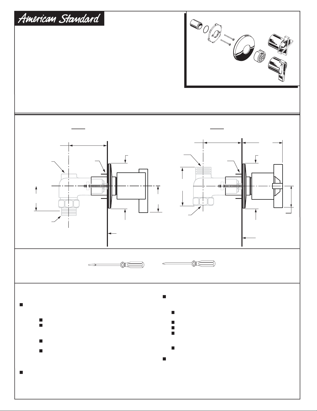
ROUGHING-IN DIMENSIONS
R701 R711
1/2" NPT 3/4" NPT
2-3/8" ± 1/2"
(60mm±13mm)
1/2" (13mm) NPT
FEMALE
OUTLET
2-1/8"
(52mm)
DIA. HOLE
2-3/4"
(70mm)
3/4'' (19mm) NPT
MALE THREADED
1-3/8" - 2-3/8"
(35mm-59mm)
OUTLET
2-1/2"
(64mm)
Certified to comply with ANSI A112.18.1M
ASSE 1016
3-1/8"
(79mm)
2-3/4"
2-1/8"
(52mm)
DIA. HOLE
(70mm)
M965001
2"
(51mm)
UNION INLET
1/2" - 14 NPT
OR
5/8" O.D.
COPPER SWEAT
FINISHED
WALL
Recommended Tools
Flat Blade Screwdriver
CARE INSTRUCTIONS:
To keep your new faucet looking new, please follow
these simple care instructions:
DO: Simply rinse the faucet clean with clear water.
Dry the faucet with a soft cotton cloth.
DO NOT:
Do not use any abrasive cleaners, cloths, or
paper towels.
Do not use any cleaning agents containing
acids, polish abrasives, or harsh cleaners or
soaps.
Regular and routine cleaning will reduce the need for
heavy cleaning and polishing. If heavy cleaning is
required, the following procedures are recommended:
LEVER
HANDLE
2-1/8"
(55mm)
3/4" NPT
FEMALE THREADED
INLET
Phillips Screwdriver
Remove as much surface dirt and film using clear
water and soft cotton cloth
Use any of the following to remove tough surface
film and build-up:
Mild liquid detergents
Clear ammonia free liquid glass cleaners
Non-acidic, non-abrasive gentle liquid or fully
dissolved powder cleansers mixed according to
manufacturers directions.
Non-abrasive liquid polishers
Once clean, rinse faucet again with clear water to
thoroughly remove cleaner or polish and blot dry with
a soft cotton cloth.
Failure to follow these care instructions may
damage the Faucet's finish.
1-1/2"
(38mm)
CROSS
HANDLE
FINISHED
WALL
(as described above).
Page 2
TRIM INSTALLATION
1
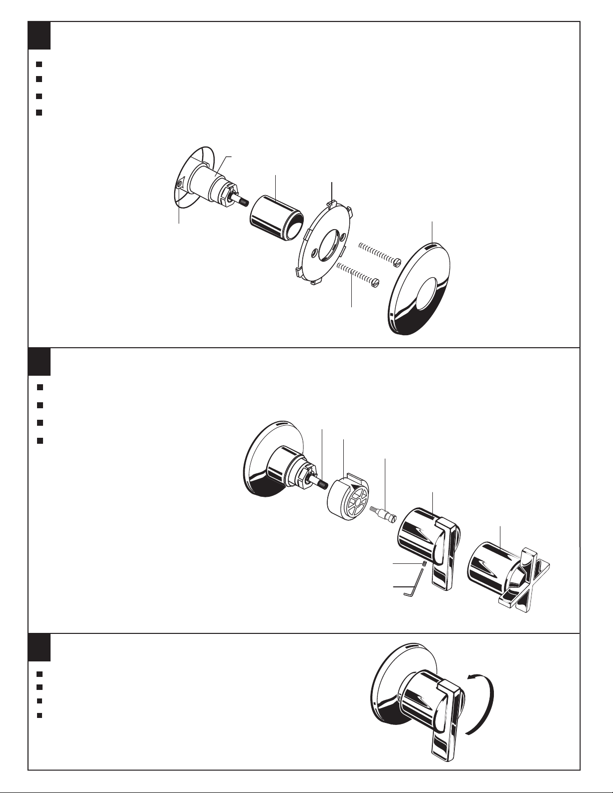
Push VALVE COVER (1) over VALVE CARTRIDGE (2) until it is seated against the stop.
Place ESCUTCHEON HOLDER (3) over VALVE COVER (1). Line up holes in ESCUTCHEON HOLDER (3) with THREADED TABS (4) on VALVE.
Install MOUNTING SCREWS (5) through ESCUTCHEON HOLDER (3) and into THREADED TABS (4). Tighten SCREWS securely.
Place ESCUTCHEON (6) over ESCUTCHEON HOLDER (3) and push evenly for a snap fit.
2
1
4
3
6
5
HANDLE INSTALLATION
2
Install HANDLE ADAPTER (1) onto VALVE STEM (2).
Install HANDLE SCREW (3) and tighten.
Align HANDLE (4, 4a) and push onto
HANDLE ADAPTER (1).
Tighten SET SCREW (5) with HEX WRENCH (6)
supplied with trim kit.
OPERATING THE VALVE
3
Turn HANDLE into OFF position.
Turn on water supplies, and check all connections for leaks.
Operate HANDLE to flush water lines thoroughly.
Turn handle OFF.
2
1
3
4
4a
5
6
ON
OFF
M965001
 Loading...