

Page 1
INSTALLATION
INSTRUCTIONS
Delancey
Single Control Lavatory Faucet
Thank you for selecting American Standard...
the benchmark of ne quality for over 140 years.
To ensure that your installation proceeds smoothly-please read
these instructions carefully before you begin.
RECOMMENDED TOOLS
®
7052121
7052124
Certied to comply with ANSI A112.18.1M
Regular Screwdriver
Adjustable Wrench
1
INSTALL LAVATORY FAUCET
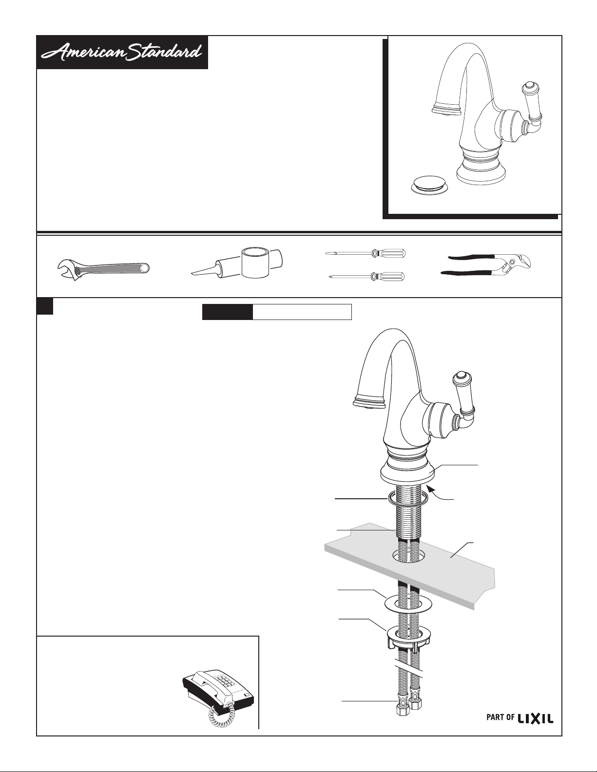
• Seat SEAL (1) into groove in under side of ESCUTCHEON BASE (2).
• Seat ESCUTCHEON BASE (2) with collar facing up into groove
in faucet base.
• Feed FAUCET SUPPLIES (3) and MOUNTING SHANK (4) through
hole in mounting surface.
• From below, install GASKET (5) and MOUNTING NUT (6) onto
SHANK (4). Secure Faucet with MOUNTING NUT (6). Before nal
tightening, adjust Faucet so that it is centered. Tighten MOUNTING
NUT (6) to complete faucet mounting.
Plumbers' Putty or Caulking
CAUTION
Turn off hot and cold water
supplies before begining.
Phillips Screwdriver
1
4
Channel Locks
2
GROOVE IN
(FAUCET BASE)
MOUNTING
SURFACE
HOT LINE FOR HELP
For toll-free information and answers to your questions, call:
1 (800) 442-1902
Mon. - Fri. 8:00 a.m. to 8:00 p.m. EST
Saturday 10:00 a.m. to 4:00 p.m. EST
IN CANADA 1-800-387-0369
(TORONTO 1-905-306-1093)
Weekdays 8:00 a.m. to 7:00 p.m. EST
IN MEXICO 01-800-839-1200
Product names listed herein are trademarks of AS America, Inc.
© AS America, Inc. 2018
- 1 -
5
6
3
M965991 (10/18)
Page 2
2
MAKE WATER SUPPLY CONNECTIONS
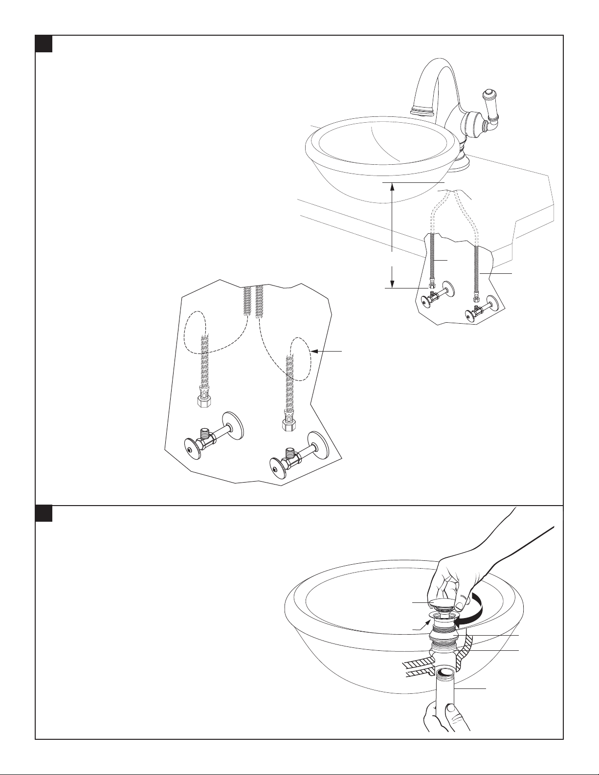
• Turn off hot and cold water supplies before beginning.
• Connect FLEXIBLE SUPPLIES (1, 2) directly to wall supplies.
Connection on tting supplies are 3/8" compression.
Connect left supply to Hot and right supply to the Cold
wall supply. Use adjustable wrench to tighten connections.
Do not over tighten.
• Faucet supplies are 28" long from faucet base.
Note: If additional supply length is required,
installer must purchase additional parts separately.
Important: If SUPPLY HOSES (1, 2) are
too long, loop as illustrated to avoid kinking.
Figure A.
Figure A.
HOT
3
DRAIN INSTALLATION
• Install DRAIN (1) by dropping it from the top of the sink.
• From under side of SINK install GASKET (2) and
MOUNTING NUT (3).
Note: Plumber’s putty or caulk is recommended.
• Thread TAIL PIECE NUT (4) clockwise onto
DRAIN BODY (2).
• Check DRAIN FLANGE in SINK to ensure that
FOAM GASKET (3) is fully compressed and
not visible.
• Operate DRAIN (1) to verify that it opens and closes.
COLD
28"
LOOP SUPPLIES
IF REQUIRED
HOT
PUTTY
2
1
COLD
1
2
3
- 2 -
4
M965991 (10/18)
Page 3
4
TEST INSTALLED FAUCET AND CHECK
FOR LEAKS
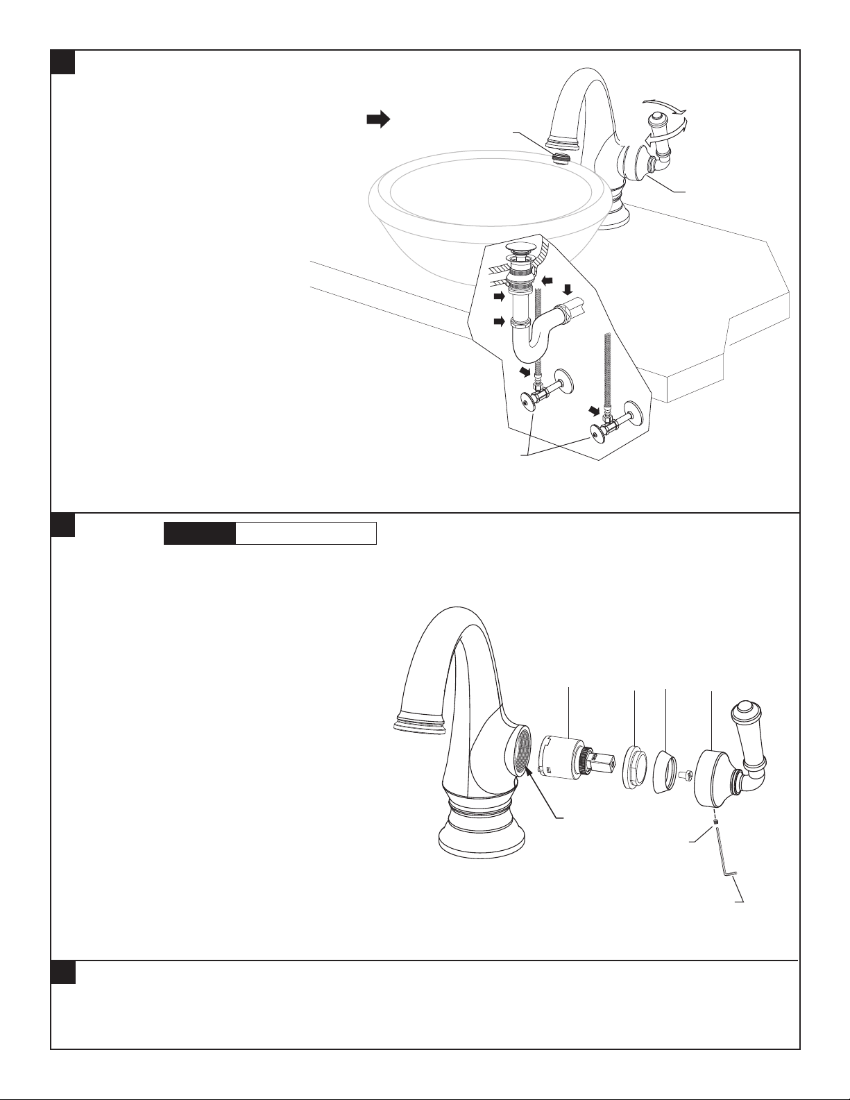
• With HANDLE (1) in OFF position, turn on WATER
SUPPLIES (2) and check all connections for leaks.
• Remove AERATOR (3).
• Operate HANDLE (1) to ush water lines thoroughly.
• Replace AERATOR (3).
3
OFF
ON
COLD
HOT
1
HOT
COLD
2
5
SERVICE
• To remove or replace cartridge:
– Turn valve to OFF position.
– Remove HANDLE SCREW (2).
– Pull off HANDLE (3) and CAP (4).
– Unthread CARTRIDGE NUT (5) and remove.
– Pull out CARTRIDGE (6).
– Inspect CARTRIDGE (6) for debris and clean
if necessary.
– Clean MANIFOLD (1) and rinse clean.
– Reinstall CARTRIDGE (6) onto MANIFOLD (1).
– Reinstall CARTRIDGE NUT (5), CAP (4) and
HANDLE ASSEMBLY (3).
• If spout drips, operate handle several times from
OFF to ON and HOT to COLD position. Do not
force - handle turns only 90˚.
CAUTION
Turn off hot and cold water
supplies before beginning.
6
4
5
3
1
2
2.5mm HEX KEY
6
CARE INSTRUCTIONS:
DO: SIMPLY RINSE THE PRODUCT CLEAN WITH CLEAR WATER. DRY WITH A SOFT COTTON FLANNEL CLOTH.
DO NOT: DO NOT CLEAN THE PRODUCT WITH SOAPS, ACID, POLISH, ABRASIVES, HARSH CLEANERS, OR A
CLOTH WITH A COARSE SURFACE.
- 3 -
M965991 (10/18)
 Loading...