

Page 1
Installation Instructions
1
S
D
)
SS
D
[
]
"
5
]
"
]
]
"
]
GE
]
"
]
"
U
O
.
T
Y
OUT
:
S
OM
.
.
.
D
)
]
-
]
"
[54mm]
GE
]
"
]
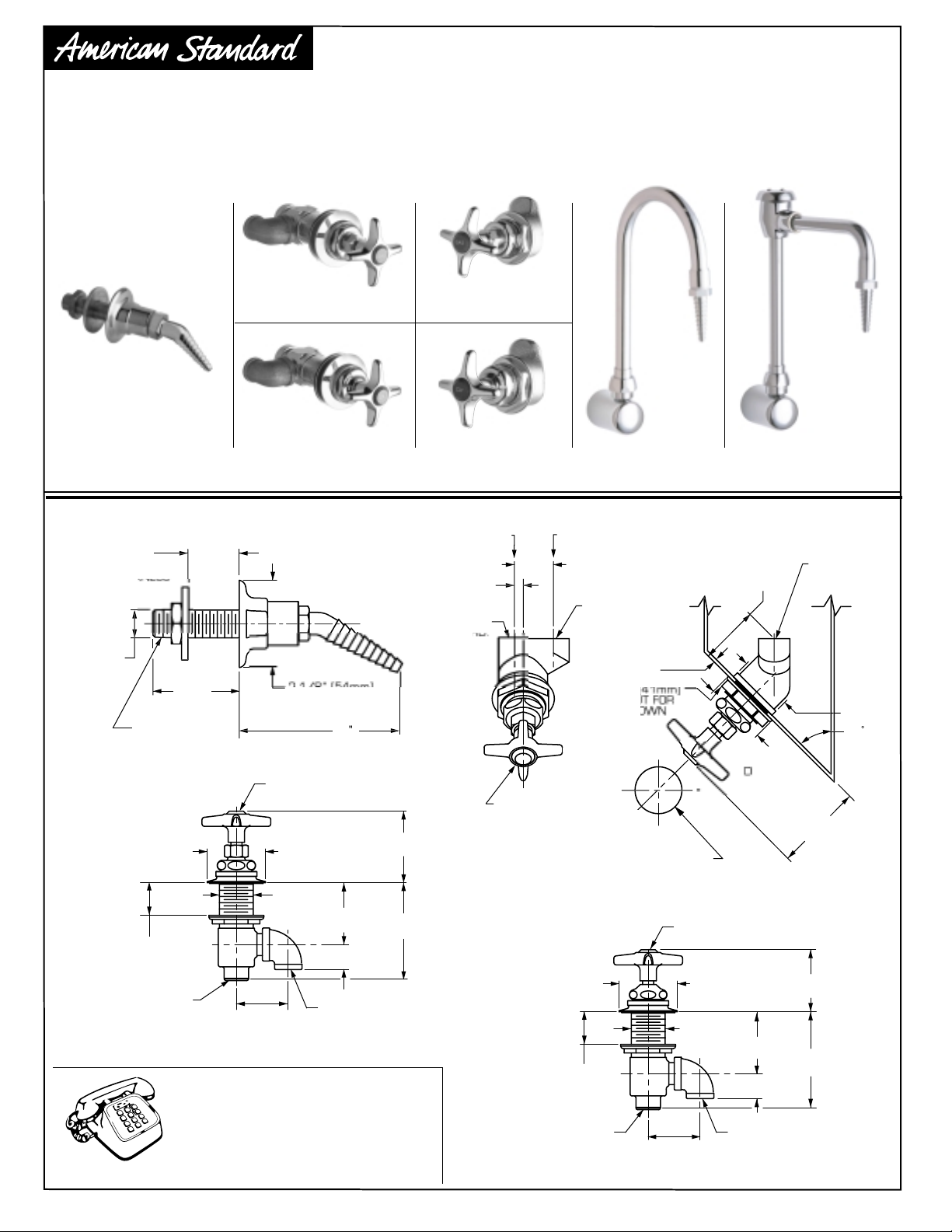
LABORATORY FUME HOOD FITTINGS
Thank you for selecting American-Standard...the benchmark of fine quality for over 100 years.
To ensure that your installation proceeds smoothly--please read these instructions carefully
before you begin.
7271.5217271.571
7271.400
ROUGHING-IN DIMENSIONS
1/16"
1-1/4
2mm-32mm
11/16
17mm
54mm
" NPT MALE
INDEX A
7271.571
1/16"-
1-1/4"
[2mm-32mm]
WARE THICKNESS
3/8" NPT
THREAD INLET
FEMALE
For toll-free information and answers to your questions, call:
1-800-387-0369 (TORONTO 1-905-306-1093)
Product names listed herein are trademarks of American Standard Inc.
(AIR, GAS, OR VAC
1-1/4"
[32mm]
1-3/4"
[45mm]
HOTLINE FOR HELP
1 (800) 442-1902
8:00 to 7:00 p.m. Eastern Time
7271.071
7271.400
DIA. FLAN
102mm
REQUIRE
2-5/8"
DIA.
2-1/8"
[54mm]
DIA.
2-1/4"
[57mm]
15/16"
[24mm]
3/8" NPT FEMALE
THREAD OUTLET
Weekdays
CANADA
©American Standard Inc. 2004
[67mm]
3-1/2"
[89mm]
7271.021
9/32
7mm
3/8" NPT FEM
1-1/4
32mm
3/8" NPT FEM
INDEX AS REQUIRE
AIR, GAS, VAC
PROVIDE 1-1/2" [38mm] DIA
PENING IN PANEL TO ACCEP
1-7/16" [37mm] DIA. BOD
7271.071
1/16"-
1-1/4"
[2mm-32mm]
WARE THICKNESS
3/8" NPT FEMALE
THREAD INLET
TLET THRD
PANEL THICKNE
NOT TO EXCEE
3mm
1/8
HEX. N
LOCK D
1-3/4"
[45mm]
271.021
271.52
INDEX 'CW'
2-1/8"
[54mm]
1-1/4"
[32mm]
7271.3017271.300
1-3/4
44mm
51mm
A. FLAN
[76mm
DIA.
DIA.
2-1/4"
[57mm]
15/16"
[24mm]
3/8" NPT FEMALE
THREAD OUTLET
2-1/4"
[57mm]
3-1/2"
[89mm]
M968484
NOTE
NLET ALWAY
N BOTT
1-3/4
44mm
4
Page 2
R
OUG
OOLS
D
]
"
]
"
]
]
]
]
"
]
"
]
"
]
"
]
]
"
]
]
]
"
]
S
)
E
S
)
OOD
GS
E
G
r
.
E
G
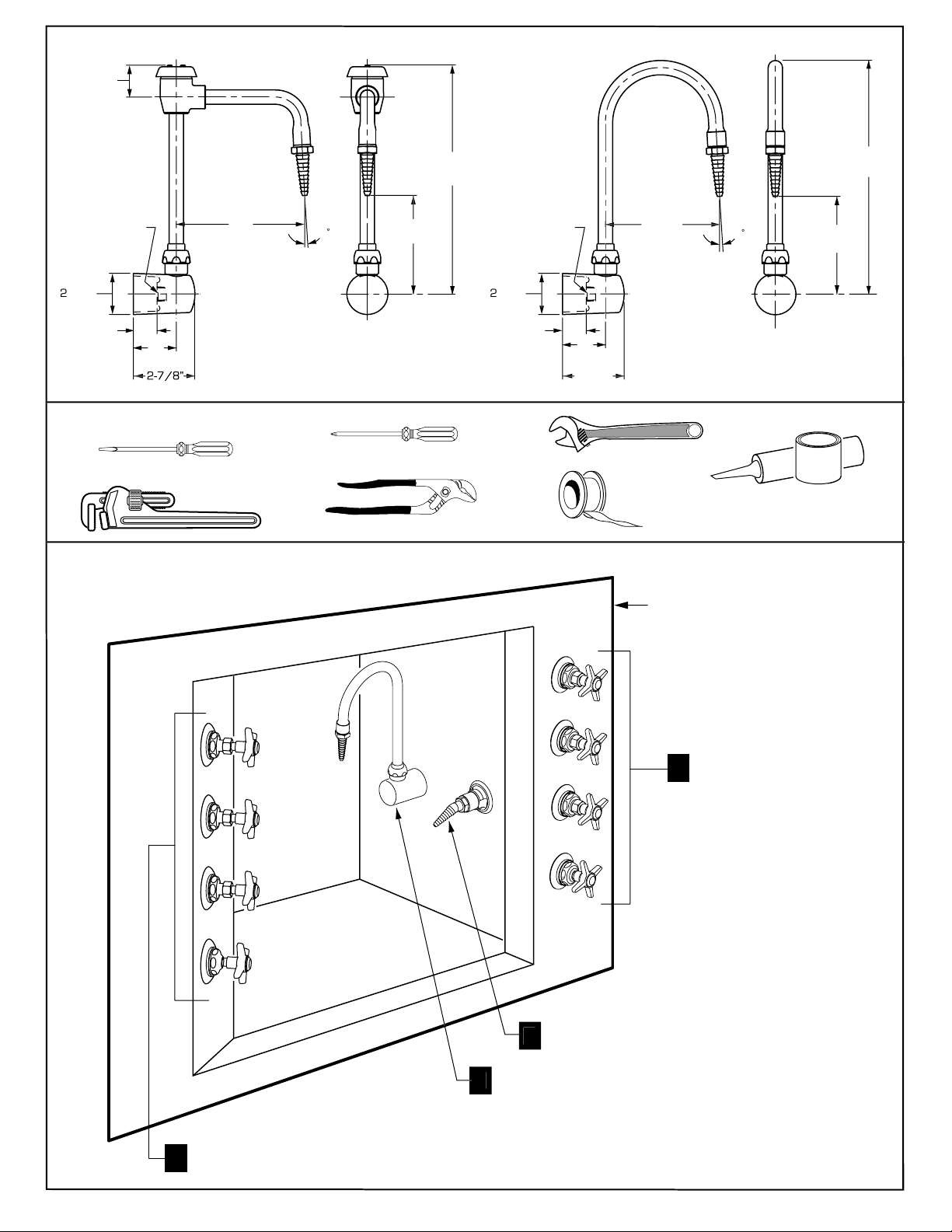
HING-IN DIMENSIONS
1-1/2
38mm
3/8" NPT FEMALE
152mm
51mm
1-1/8
T
[29mm
2
51mm
73mm
AND SUPPLIES REQUIRE
Flat Blade Screwdriver
7271.301 7271.300
Pipe Wrench
FUME HOOD FITTIN
For installation of products refe
o steps one to four
10-3/4
4-1/2
114mm
Phillips Screwdriver
Channel Locks
273mm
3/8" NPT FEMALE
51mm
1-1/8
[29mm
51mm
2-7/8
73mm
137mm
Adjustable Wrench
Teflon Tape
TYPICAL FUME H
Plumbers' Putty or
Caulking
[279mm
4-1/2
[114mm
FRONT-LOADED VALVE FOR ANGLED PANEL
1
AIR, GAS, VACUUM, WATER
WALL MOUNTED REMOT
NTROL OUTLET FITTIN
WALL MOUNTED REMOT
NTROL OUTLET FITTIN
FRONT-LOADED VALV
FOR STRAIGHT PANEL
2
AIR, GAS, VACUUM OR WATER
M968484
Page 3
968484
Y
R
UT
W
:
e
e
y
t
e
.
s
5
angled fume hood equipped with 1-1/2" (38.1mm) diameter
l
.
s
h
e
h
o
stalled such that the
bottom.
D
OOD
UT
GE
E
OSS
E
UT
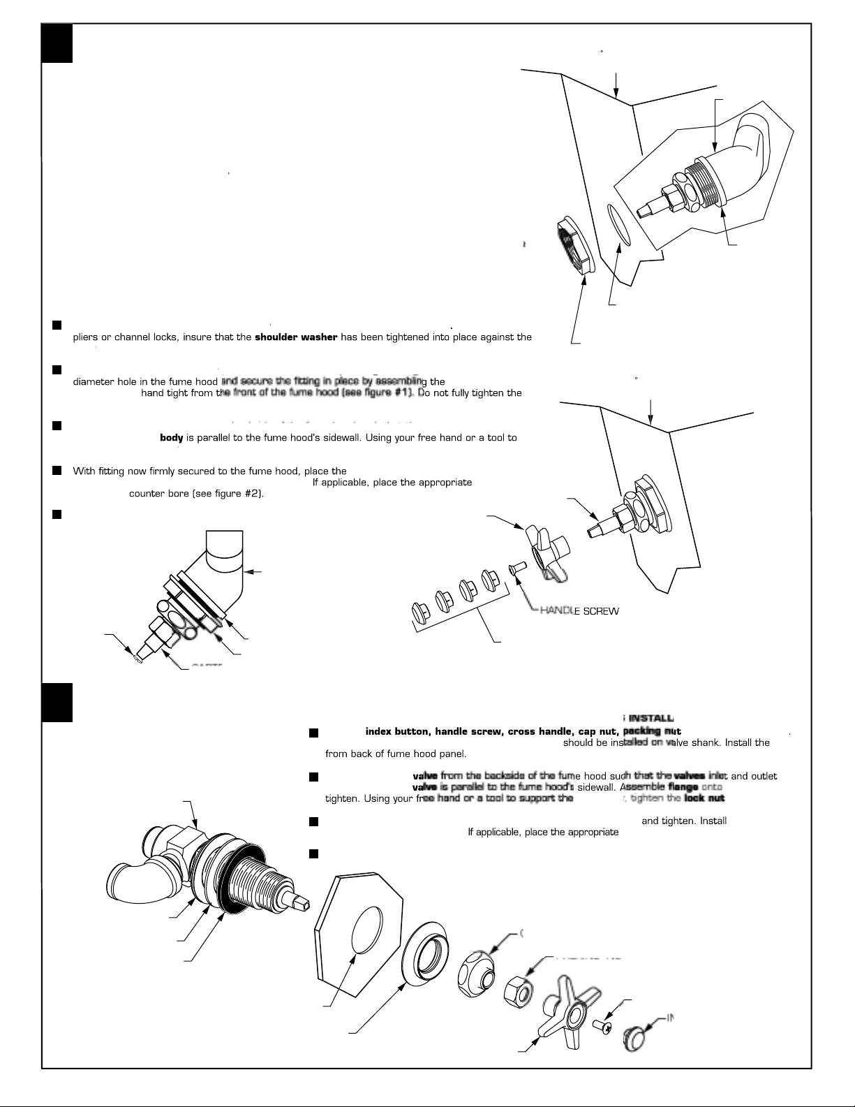
INSTALL FRONT-LOADED ANGLE CONTROL VALVE, 7271.021/52
1
)
)
W
ON
R
R
Y
1
R
R
)
E
UT
e
e
ut
e
e
d
y
y.
t
e
secure
.
button
counter bore.
s.
S
)
M
2
D
OOD
.
e
and the
f
such that the threads on the two components lock together.
ace the
y
(end which contains the operating cartridge) through the 1-1/2"
ut
y
e.
outlet
e
y
from the backside, tighten the
y.
t
.
button
e
s.
1
AIR, GAS, VACUUM, WATER
Important service note
he Faucet Panel mounted fume hood fitting has been designed such that future servicing of th
itting's cartridge can be done from the (user's) side of the fume hood. To do this, insure that th
main supply valve to the fitting has been completely turned off and then purged by completel
pening the fitting and releasing trapped material into the fume hood atmosphere. Then, suppor
he entire fitting by holding the hold-down nut in place with a wrench, before loosening th
artridge's cap nut
his Panel mounted fume hood valve has been shipped as shown below to ease installation. It i
esigned to be installed in a 4
mounting holes. Before proceeding with the installation, identify and familiarize yourself with al
f the components
Important Note: The front load fume hood fittings described in these installation instruction
re available in both right hand and left hand models. Right hand models are marked on bot
sides of the body with an "R" and left hand models are similar marked with an "L". Due to th
se of these fittings in both right and left hand fume hoods, the bodies are marked on bot
sides with directional flow arrows. Regardless of the model used, the fittings are designed t
in
inlet is on the
45ANGLE
FUME H
FIGURE
BOD
HOULDE
WASHE
IMPORTANT: FLUSH ALL SUPPLY LINES PRIOR TO FITTING INSTALLATION
Remove thehold-down nut from th
Pl
hold-down nut at this tim
support the valve bod
into place with the
intohandl
Complete the inlet and outlet piping to the fitting and check for leak
RE
front end of thebod
nto thebod
re in line and th
crew removed from thetem
BOD
HOULDER WASHE
HOLD DOWN N
handle screwfrom thetem With a pair o
hold-down n
body's inlet and
hold-down nut securel
handle onto thetem and tighten i
index
INSTALL FRONT-LOADED VALVE FOR STRAIGHT PANELS, 7271.071/571
2
AIR, GAS, VACUUM, WATER
Remov
Rubber seal washer, steel washer andlock n
1-1/2" (38.1mm
MOUNTING HOL
HOLD DOWN N
45ANGLE
FUME H
FIGURE
TE
INDEX BUTTON
AIR, GAS, VACUUM, WATER
andflange from valv
valv
LOCK N
TEEL WASHE
RUBBER WASHE
HOOD MOUNTING HOL
Align the mounted
re in line and th
With valve now firmly secured to the fume hood install the cap nu
nd
Complete the inlet and outlet piping to the valve and check for leak
FLAN
with handle screw
R
AP N
HANDL
valve bod
index
HANDLE SCRE
valve an
securel
cross handl
intohandle
DEX BUTT
M
Page 4
301
300
UT
Y
H
H
0A
0A
Y
WALL MOUNTED REMOTE CONTRO
L
WALL MOUNTED REMOTE CONTROL OUTLET
1
S
UT
R
E
)
g.
g
l
ut.
t
n
.
s.
m
.
counter cloc
oosen and remove
.
pe
.
ead
onto
t
.
ead
onto
and tighten.
L
OOD
CUU
R
0A
OUT
0A
S
0A
0A
G
T
T
dex
0A
00
962315-00
d
0
962313-007
007
GE
0A
330-0070A
GE
336-0070A
I
336-007
:
R
3
Removelock nut andteel washer from fittin
Align and mountfitting from the front side of the fume hood. Usin
washer andlock n
h fitting now firmly secured to the fume hood complete the i
Wi
piping to the fitting. (See rough-in for piping requirements)
Turn supply to fitting on and check for leak
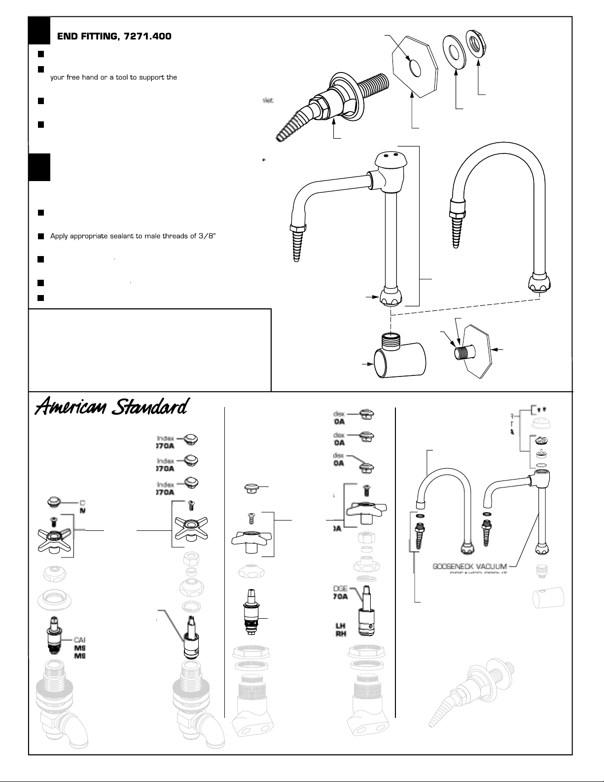
FITTING (GOOSE NECK SPOUTS), 7271.300/30
4
Note: See roughing-in to determine pipe nipple length fro
ide wall
Turn spout nut
spout assemblyfrom
nipple (See rough-in for piping requirements)
Thr
assemblyis vertical
Thr
Turn supply tofitting on and check for leaks.
tighten the lock nut securely.
k-wise to l
itting base
ipe nipple and align so thatspou
fitting body and install
i
HOOD MOUNTING HOL
1-1/4" DIA. (32mm
tee
LOCK N
TEEL WASHE
FUME HOOD WAL
FITTIN
POUT ASSEMBL
POUT N
ARE INSTRUCTIONS
DO: SIMPLY RINSE THE PRODUCT CLEAN WITH CLEA
WATER. DRY WITH A SOFT COTTON FLANNEL CLOTH.
DO NOT: CLEAN THE PRODUCT WITH SOAPS, ACID,
POLISH, ABRASIVES, HARSH CLEANERS, OR A CLOTH
WITH A COARSE SURFACE.
AVAILABLE REPAIR PART
M962313-
AIR
VAC
M
2312-007
M962310-002
ARTRID
M962
2329-0070A L
62330-0070A R
M
M962314-
VAC In
M962315-007
W In
2312-007
M962310-002
ARTR
M962
ARTRID
M962329-007
M962
SPOUT BOD
AS In
3/8" NP
M962316-002
ERRATED TIP
M962318-002
271.
APPLY SEALAN
VA
M BREAKE
M962322-007
ENECK SP
M962317-002
FUME H
271.
7271.071
7271.571
7271.021
7271.521
7271.400
M968484
 Loading...