

American Standard 7075.050, 7075.054, 7075.005, 7075.004, 7075.006 Installation Instructions Manual
...
F.W. WEBB COMPANY- O & M
PLUMBING, HEATING, COOLING, AND INDUSTRIAL SUPPLIES
SERVING NEW ENGLAND & NEW YORK SINCE 1866
WARREN MECHANICAL
O&M FIXTURES
HARTLEY BLOCK
06/08/2018
Erica Bryant @ FW
07/29/2016
150 Postal Service Way • South Portland, Maine
Phone: (207) 772-8364 Fax: (207) 773-4571
Webb Co.
INSTALLATION
INSTRUCTIONS
P-2, P-2B - 7075.050
COLONY® PRO
SINGLE CONTROL
CENTERSET
7075.054 / 7075.055 / 7075.056
7075.050 / 7075.004 / 7075.005
7075.006 / 7075.002 / 7075.000
LAVATORY FAUCET
Thank you for selecting American Standard...
the benchmark of fine quality for over 100 years.
To ensure that your installation proceeds smoothly-please read
these instructions carefully before you begin.
RECOMMENDED TOOLS
Screwdriver Adjustable Wrench Tubing CutterChannel Locks
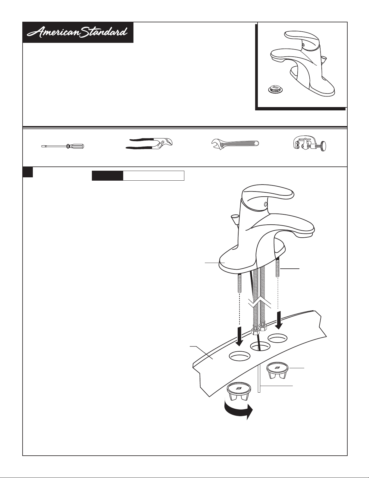
1
INSTALL FAUCET
• Insert FAUCET (1) and POP-UP CABLE (2) through mounting
holes of Sink or Mounting Surface.
• Assemble LOCKNUTS (3) onto SHANKS (4) from under
side of Sink. Hand tight
CAUTION
Turn off hot and cold water
supplies before begining.
Certied to comply with ANSI A112.18.1M
SINK OR
MOUNTING
SURFACE
(HAND TIGHTEN)
1
4
3
2
Product names listed herein are trademarks of AS America, Inc.
© AS America, Inc. 2016
- 1 -
M965766 (8/16)
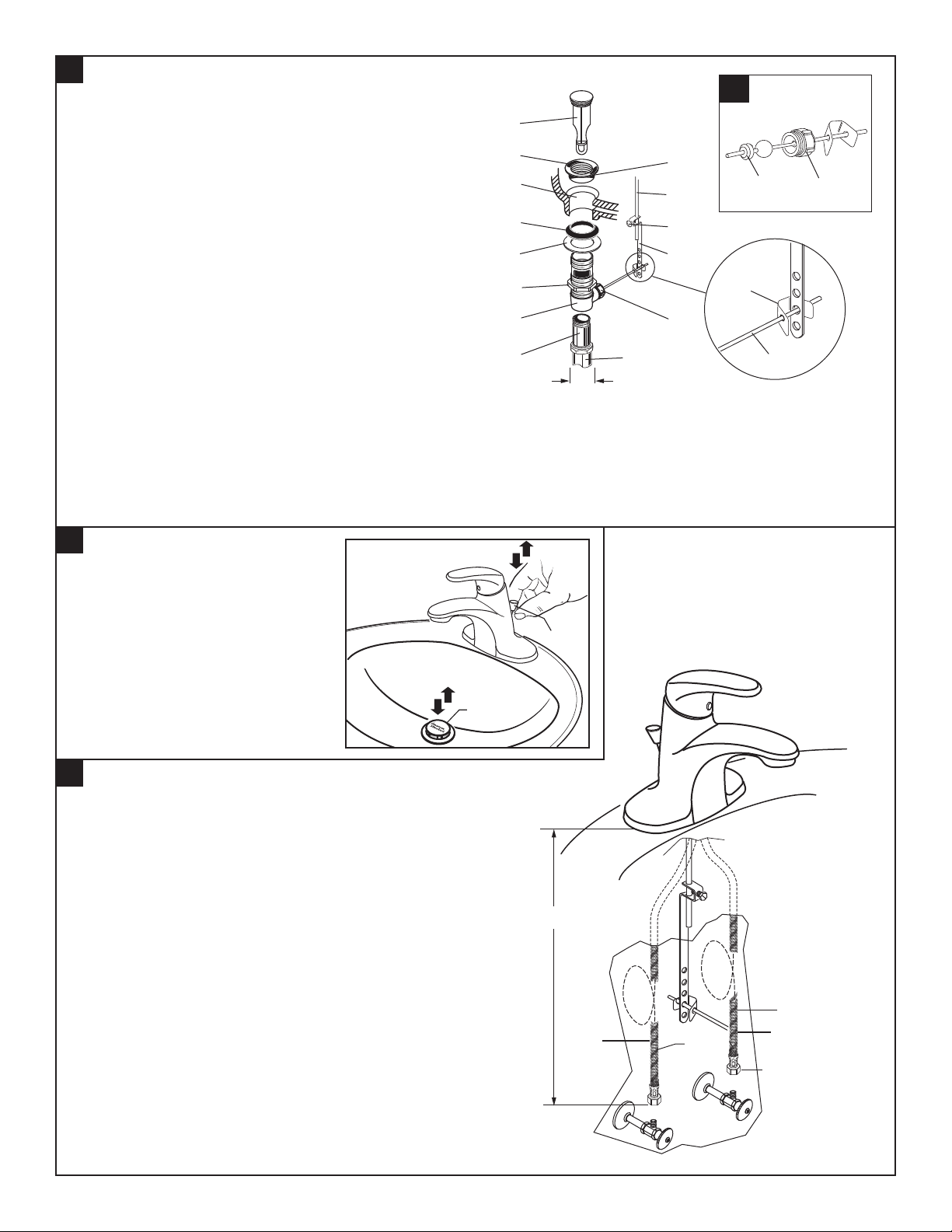
2
INSTALL POP-UP DRAIN
P-2, P-2B - 7075.050
2a
• Push TAIL PIECE (11) down into TRAP (C) (threaded end up).
• Thread LOCKNUT (5), WASHER (4) and GASKET (3)
(Bevel side up) onto DRAIN BODY (10).
• Apply a bead of PUTTY (D) to underside of FLANGE (2).
• Feed DRAIN BODY (10) up through SINK (A) and thread
the FLANGE (2) fully onto DRAIN BODY (10).
• Tighten LOCKNUT (5) rmly, keeping the pivot rod hole pointed
towards the back of the sink.
• Assemble PIVOT ROD (9) as shown in Figure-2a.
Notice the position of the CONCAVE WASHER (G).
• Insert PIVOT ROD (9) into DRAIN BODY (10) and tighten
PIVOT NUT (F).
• Pull TAIL PIECE (11) up and thread tightly into
DRAIN BODY (10).
• Position EXTENSION ROD (7) onto POP-UP ROD (E) and tighten
THUMBSCREW (6).
• Remove one end of CLIP (8) from PIVOT ROD (9) by squeezing ENDS TOGETHER WHILE SLIDING.
• Insert PIVOT ROD (9) into second or third hole in EXTENSION ROD (7) and reassemble CLIP (8).
• DROP STOPPER (1) into DRAIN BODY (10).
• Adjust stopper height by repositioning EXTENSION ROD (7) and tightening THUMBSCREW (6).
3
CHECK OPERATION OF POP-UP
A
4
10
11
1
2
3
5
C
1-1/4"
D
E
G
F
6
7
8
F
9
• Operate LIFT KNOB (1) to verify that
STOPPER (2) opens and closes.
4
MAKE WATER SUPPLY AND WASTE CONNECTIONS
• Connect FLEXIBLE SUPPLIES (1, 2) directly to wall supplies.
Connection on tting supplies are 3/8" compression.
Connect left SUPPLY (1) to Hot (Marked with a Red Band)
and right supply to COLD (2) wall supply.
• Faucet supplies are 20" long from faucet base.
Note: If additional supply length is required, installer must
purchase additional parts separately.
Important: If SUPPLY HOSES (1, 2) are to long, loop as
illustrated to avoid kinking.
• Connect 1-1/4” O.D. tailpiece on POP-UP DRAIN to
waste outlet.
2
1
APPROX. 20"
2
1
RED
BAND
BLUE
BAND
3/8" COMPRESSION
- 2 -
HOT
COLD
M965766 (8/16)
5
TEST INSTALLED FITTING
• With HANDLE (1) in OFF position, turn on WATER
SUPPLIES (2) and check all connections for leaks.
Remove AERATOR (3).
•
Operate HANDLE (1) to ush water lines thoroughly.
•
Replace AERATOR (3).
•
CHECK DRAIN CONNECTIONS
• Operate POP-UP KNOB (4) and ll lavatory with water.
Check that DRAIN STOPPER (5) makes a good seal
and retains water in Sink.
Release POP-UP KNOB (4) down and check all drain
•
connections and “P” trap for leaks. Tighten
if necessary.
WASTE
OUTLET
P-2, P-2B - 7075.050
ON
OFF
COLD
1
HOT
3
4
2
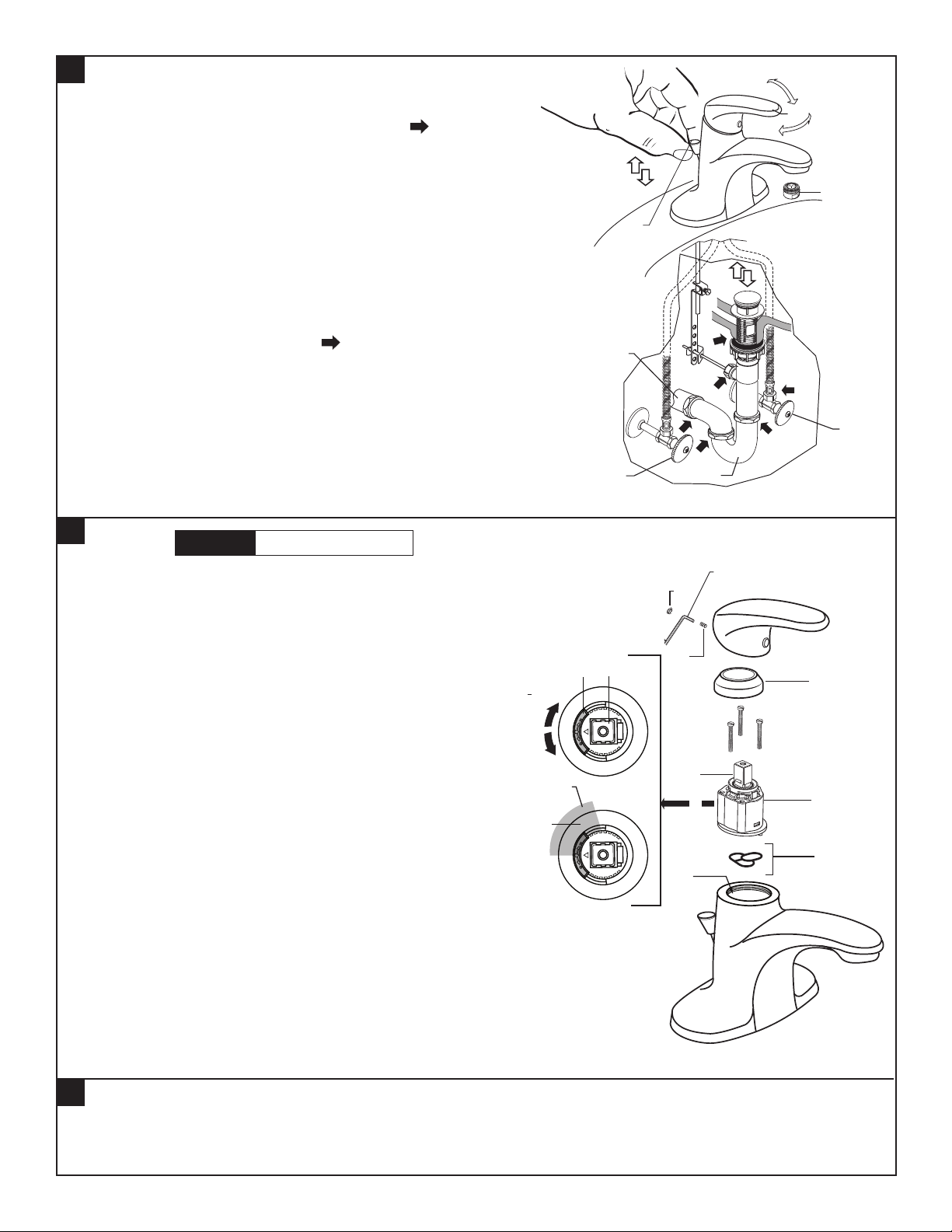
6
SERVICE
CAUTION
Turn off hot and cold water
supplies before beginning.
• To remove or replace cartridge:
– Turn valve to OFF position.
– Pull out PLUG BUTTON (1) and remove HANDLE SCREW (2).
– Pull off HANDLE (3) and CAP (4).
– Pull out CARTRIDGE (5).
– Inspect CARTRIDGE (5) and O-RINGS (6) for debris and
clean if necessary.
– Clean MANIFOLD (7) and rinse clean.
– Reinstall CARTRIDGE (5) and O-RINGS (6) onto
MANIFOLD (7).
– Reinstall CAP (4) and HANDLE ASSEMBLY (3).
If spout drips, operate handle several times from OFF to ON
•
and HOT to COLD position. Do not force - handle turns only 90˚.
ADJUST HOT LIMIT SAFETY STOP
By restricting HANDLE rotation and limiting the amount of
hot water allowed to mix with the cold, the HOT LIMIT SAFETY
STOP (8) reduces risk of accidental scalding. To lower the
maximum hot water temperature of your faucet, all you need to
do is adjust the setting on the HOT LIMIT SAFETY STOP (8).
Note: The HOT LIMIT SAFETY STOP (98 is set at the neutral
setting from the factory. Fig. A.
To adjust HOT LIMIT SAFETY STOP:
•
– Remove HANDLE ASSEMBLY (3), CAP (4)
– Set the CARTRIDGE STEM (9) to the OFF position.
– Lift up the HOT LIMIT SAFETY STOP 8).
– Place the HOT LIMIT SAFETY STOP (8) in the desired GRAY
SHADED AREA (10) to limit the hot water. Fig. B.
– Reinstall CAP (4) and HANDLE ASSEMBLY (3).
COLDER
+HOTTER
SETTING
MARKS
10
2
“P” TRAP
2.5mm HEX KEY
1
2
9
8
4
A
9
B
8
5
6
7
7
CARE INSTRUCTIONS:
DO: SIMPLY RINSE THE PRODUCT CLEAN WITH CLEAR WATER. DRY WITH A SOFT COTTON FLANNEL CLOTH.
DO NOT: DO NOT CLEAN THE PRODUCT WITH SOAPS, ACID, POLISH, ABRASIVES, HARSH CLEANERS, OR A
CLOTH WITH A COARSE SURFACE.
- 3 -
M965766 (8/16)
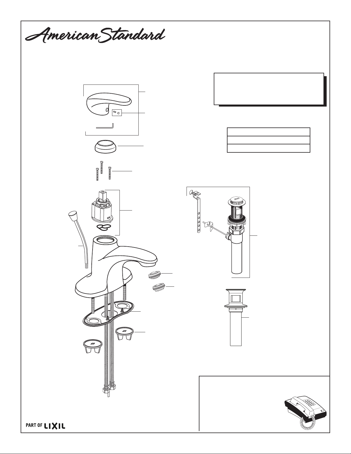
M970184-YYY0A
HANDLE KIT
M970194-YYY0A
SET SCREW & BUTTON
& INDEX BUTTON RED/BLUE
M907315-YYY0A
CARTRIDGE CAP
M918511-0070A
CARTRIDGE SCREWS
P-2, P-2B - 7075.050
COLONY® PRO
SINGLE CONTROL
CENTERSET
LAVATORY FAUCET
MODEL NUMBERS
7075.054 / 7075.055 / 7075.056
7075.050 / 7075.004 / 7075.005
7075.006 / 7075.002 / 7075.000
Replace the “YYY” with
appropriate finish code
POLISHED CHROME 002
LEGACY BRONZE 278
SATIN NICKEL 295
M970185-YYY0A
LIFT ROD
M951483-0070A
CARTRIDGE
M910942-0070A
PUTTY PLATE
044912-0070A
MOUNTING NUT
M953465-YYY0A
PLASTIC DRAIN ASSEMBLY
M953450-YYY0A
METAL DRAIN ASSEMBLY
M964479-0070A
AERATOR (1.2 GPM)
M922917-0070A
AERATOR (0.5 GPM)
M953455-YYY0A
GRID DRAIN
- 4 -
HOT LINE FOR HELP
For toll-free information and answers to your questions, call:
1 (800) 442-1902
Mon. - Fri. 8:00 a.m. to 8:00 p.m. EST
Saturday 10:00 a.m. to 4:00 p.m. EST
IN CANADA 1-800-387-0369
(TORONTO 1-905-306-1093)
Weekdays 8:00 a.m. to 7:00 p.m. EST
IN MEXICO 01-800-839-1200
M965766 (8/16)
P-3 - SYMMONS 9602-XP
Origins
S-9600-P, S-9600TS-P, S-9601-P, S-9602-P
Operation & Maintenance Manual
Model Numbers
S-9600-P
Origins Shower Valve
S-9600TS-P
Origins Tub/Shower Valve
S-9601-P
Origins Shower System
S-9602-P
Origins Tub/Shower System
Modifications
-1.5 1.5 gpm (5.7 L/min) flow restrictor
-2.0 2.0 gpm (7.6 L/min) flow restrictor
-231 Super showerhead in place of Clear-Flo
-295 Institutional showerhead in place of
-SS Slip spout on any tub/shower unit
-X Integral service stops
-CHKS Integral check stops
-IPS 1/2” female IPS connections
-REV Reverse coring for back to back
-B Chrome brass escutcheon
-D Chrome brass dome cover
-VP Vandal proof escutcheon screws
-OP 13” oval plate
-L/HD Less showerhead
-TRM Trim only, valve not included
Clear-Flo
installations
™
Specification
S-9600-P/S-9601-P
Shower system powered by the Temptrol® Pressure
Balancing valve. Features adjustable stop screw to
limit handle turn, integrated volume control, 1 mode
showerhead with easy to clean rubber nozzles and
standard 2.5 gpm (9.5 L/min) ow restrictor. Components
made from metal and nonmetallic materials plated in
standard polished chrome nish.
S-9600TS-P/S-9602-P
Tub/shower system powered by the Temptrol® Pressure
Balancing valve. Features adjustable stop screw to limit
handle turn, integrated diverter, non-diverter tub spout, 1
mode showerhead with easy to clean rubber nozzles and
standard 2.5 gpm (9.5 L/min) ow restrictor. Components
made from metal and nonmetallic materials plated in
standard polished chrome nish.
Compliance
-ASME A112.18.1/CSA B125.1
-WaterSense 1.5 gpm (5.7 L/min)
2.0 gpm (7.6 L/min)
For California Residents
WARNING: This product contains chemicals known to
the State of California to cause cancer, birth defects, or
other reproductive harm.
Warranty
Limited Lifetime - to the original end purchaser in
consumer/residential installations.
5 Years - for industrial/commercial installations.
Refer to www.symmons.com/warranty for complete
warranty information.
Certied by
CSA Group
Note: Append appropriate -sufx to model number.
 Loading...