

American Standard 7038.400 User Manual
Installation
Instructions
TROPIC
Bidet Faucet and Transfer Valve with
EverClean™ Finish & SpeedConnect™ Drain
Congratulations on purchasing your American Standard
faucet with EverClean finish and Speed Connect drain, two
features found only on American Standard faucets.
7038.400
EverClean Finish
• One wipe effortlessly removes spots
• Eliminates the need for cleaners and scrubbing
• Permanent surface protectant remains beautiful
for the life of the faucet
• EverClean™ available on: Polished Chrome, Satin Nickel,
SpeedConnect Drain*
• Fewer parts, installs in less time
• Never needs adjustment
• Guaranteed to seal properly the first time, every time.
Certified to comply with ANSI A112.18.1
M968893
Stainless Steel, Polished Brass (or any combination of these finishes)
*Your new American Standard faucet is designed to work only with the SpeedConnect drain.
To ensure that your installation proceeds smoothly-please read these instructions carefully before you begin.
2
1
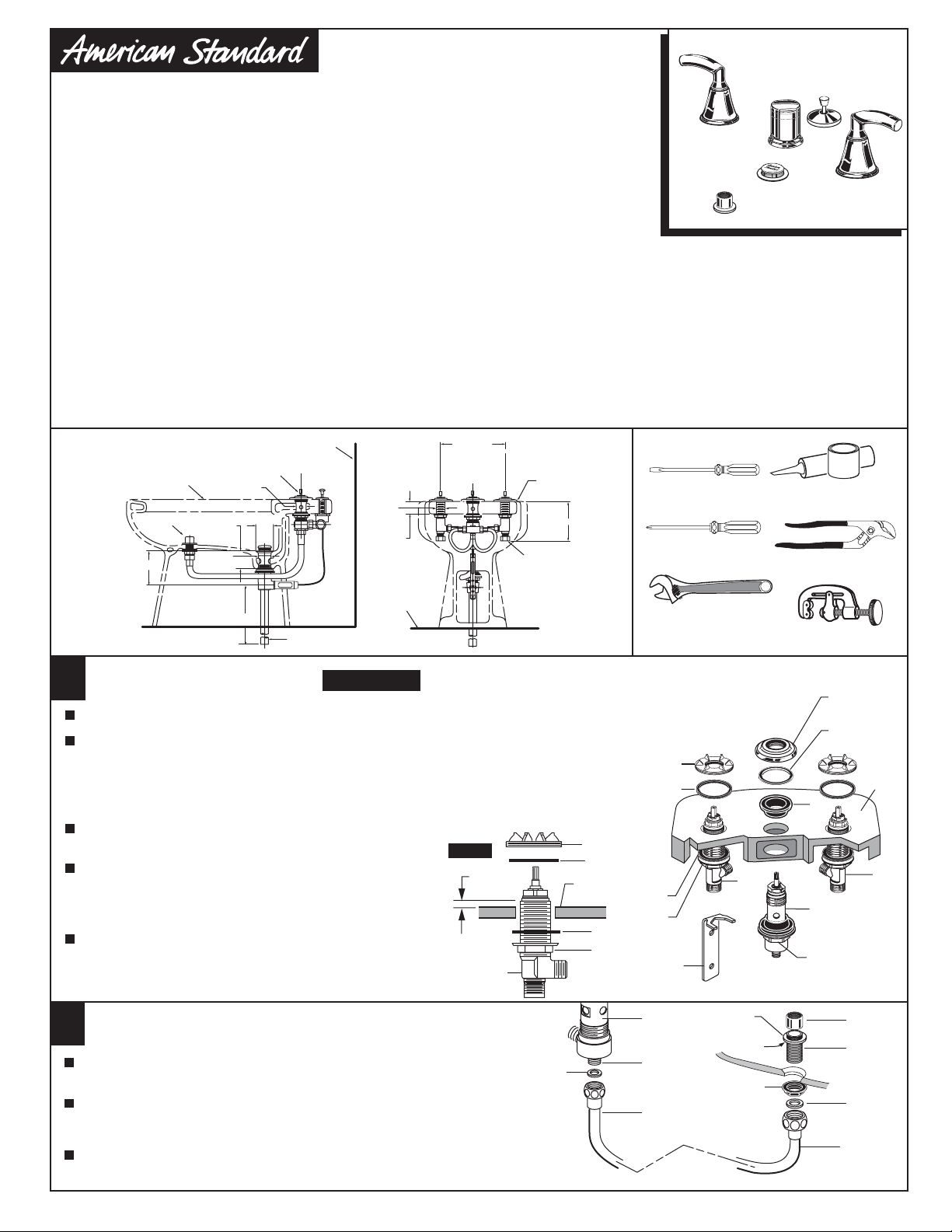
Required tools
Screwdriver
Phillips Screwdriver
Adjustable Wrench
4
10
2
HOT
1
5
3
Plumbers' Putty or
Caulking
Channel Locks
Tubing Cutter
6
7
8
COLD
9
11
Roughing-in
Dimensions
BIDET OUTLINE
IS SYMBOLIC
DOUCHE
SPRAY
3-7/8
BIDET FAUCET INSTALLATION
1
TRANSFER VALVE
(FOR FLUSHING
RIM OR SPRAY)
7/8 DIA.
ADJ. 1-1/4
TO 2-1/4
1-3/8
DIA.
5-1/2
FINISHED
WALL
2-1/8
DIA.
1-1/4 O.D. TAILPIECE
1-3/16
DIA.
1-1/4
MAX.
FINISHED
FLOOR
CAUTION
8 TO 12
(C)
Turn off hot and cold water
supplies before beginning.
(H)
2-1/4
DIA.
4-1/4
FOR GROUND JOINT
CONNECTION OR 1/2 "
O.D. SLIP (INLETS)
REAR VIEW WITH
WALL REMOVED
Place RUBBER RING (10) into DECK ADAPTER (4).
Install LOCKNUT (1) and RUBBER WASHER (2) onto VALVE BODIES (3, 3a). From
under side of mounting surface, install VALVE BODY (3, 3a) through valve mounting
holes. Threads of VALVE BODY (3, 3a) should extent at least 5/16 of a inch above
mounting surface top. Fig. A. Thread DECK ADAPTER (4) onto VALVE BODIES (3, 3a)
until snug against internal stop. If necessary, adjust LOCKNUT (1).
Tighten LOCKNUTS (1) with WRENCH (5) (supplied)
to secure VALVE BODIES (3, 3a).
Remove ESCUTCHEON (6), WASHER (7) and
UPPER GASKET (8) from TRANSFER VALVE (9).
Insert TRANSFER VALVE (9) into the center forward
Fig. A.
5/16''
MIN.
MOUNTING
SURFACE
hole of BIDET.
Replace UPPER GASKET (8) and WASHER (7) and
ESCUTCHEON (6) until it locks against internal stop.
Position the side threaded outlet rearward and
secure MOUNTING NUT (11).
3, 3a
4
10
BIDET
LEDGE
3a
SPRAY INSTALLATION
2
Assemble SPRAY BODY (1) to BIDET. Using putty, seal underside
of SPRAY BODY FLANGE (2) and secure with NUT (3).
Thread SPRAY HOSE (4) with SEAL WASHER (5) to SPRAY BODY (1).
Connect other end of HOSE (4) with SEAL WASHER (6) to side outlet
NIPPLE (7) of the TRANSFER VALVE (8).
Thread SPRAY CAP (9) onto SPRAY BODY (1).
1
8
6
7
2
PUTTY
9
1
3
4
5
4
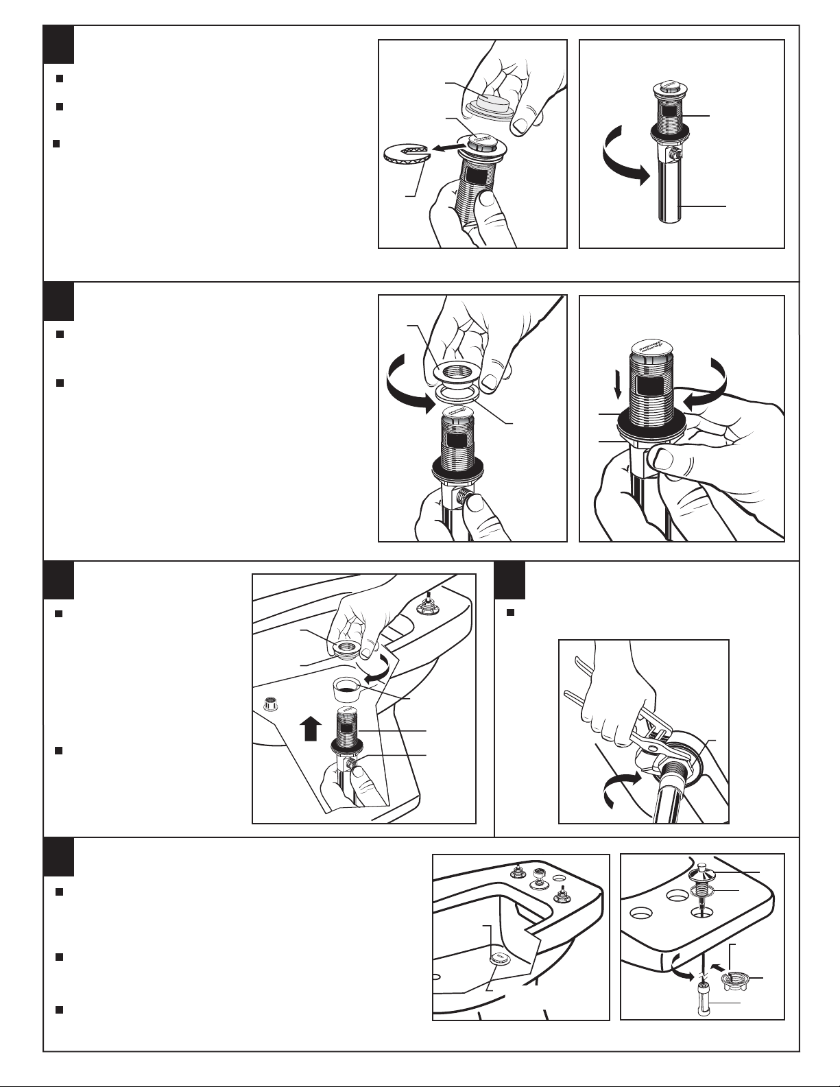
POP-UP DRAIN
3
Fig. A. Fig. B.
Remove CLEAR PLASTIC COVER (1).
Remove CARDBOARD SPACER (2) from under
DRAIN POP-UP (3).
Tighten TAILPIECE (4) on DRAIN BODY before
installing DRAIN BODY.
REMOVE FLANGE
4
Thread FLANGE (1) counter-clockwise and remove
FLANGE (1) and FOAM GASKET (2) from drain
body.
Fig. A.
Thread LOCKNUT (3) clock-wise to bottom of
drain body. Push GASKET (4) down against
LOCKNUT (3).
Fig. B.
Fig. B.
1
3
2
Fig. A. Fig. B.
1
2
4
3
DRAIN
BODY
4
INSTALL DRAIN FROM
5
BELOW FIXTURE
From under side of BIDET
install DRAIN BODY (1) up
through drain outlet.
Note: No plumber’s putty
or caulk is required.
The CABLE ATTACHMENT
POINT (2) must face towards
the rear of the BIDET.
Install FOAM GASKET (3) and
FLANGE (4) onto drain body
from above BIDET and tighten
FLANGE (4) firmly.
FLANGE GASKET
7
Check DRAIN FLANGE in BIDET to ensure that WHITE
FOAM GASKET (1) is fully compressed and not visible.
Fig. A.
POP-UP ROD ASSEMBLY
Insert LIFT ROD GUIDE (1) and CABLE CONNECTOR (2)
through rear hole, making sure SEAL WASHER (3) is
properly seated. Fig. B.
From below slip slot in MOUNTING NUT (4) over CABLE (5).
Thread NUT (4) onto lift rod guide shank to secure ROD
GUIDE (1) to bidet. Hand tighten only. Fig. B.
4
3
DRAIN
OUTLET
1
2
Fig. A.
DRAIN
FLANGE
2
TIGHTEN LOCKNUT
6
Tighten LOCKNUT (1) firmly with Adjustable
Wrench or Channel Locks.
Fig. B.
WHITE FOAM
1
GASKET
NOT VISIBLE
ILLUSTRATION
SHOWN LESS
VALVES
1
3
SLOTTED
MOUNTING
NUT
2
M968893
1
4
ATTACH CABLE
8
CONNECTOR
Fig. A.
Fig. B.
Fig. C.
POP-UP KNOB (1) must be fully
down. Fig. A.
Thread CABLE CONNECTOR (1)
clockwise onto DRAIN BODY
CONNECTION (2) and hand
tighten. Fig. B.
Your new POP-UP DRAIN
installation is now complete.
Fig. C.
Note: Tailpeice on pop-up drain
is 1-1/4” O.D. Fig. C.
CHECK OPERATION OF POP-UP
9
Operate LIFT KNOB (1) to verify that STOPPER (2)
opens and closes.
Note: If STOPPER (2) does not open and close properly
then refer to the “troubleshooting section” of these
instructions.
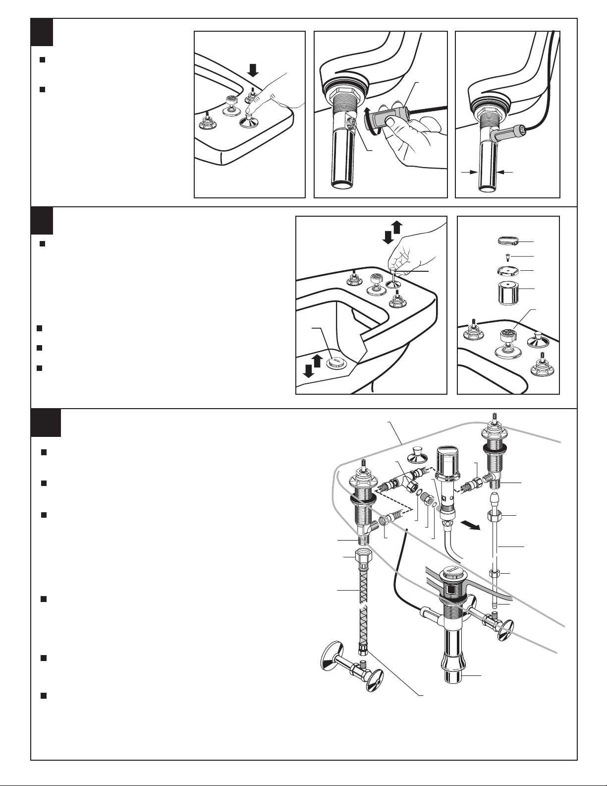
INSTALL DIVERTER KNOB
Push DIVERTER KNOB (1) onto HANDLE ADAPTER (2).
DOWN
1
2
1-1/4” O.D.
5
4
1
2
3
1
2
Push on RING (3) and tighten with SCREW (4).
Press on KNOB CAP (5).
Note: Screwdriver gap is for disassembling and should
point downwards.
10
TEE AND HOSE CONNECTION
Insert SEAL (1) into ADAPTER (2) and tighten ADAPTER (2) to
side of TRANSFER VALVE (3).
Install SEAL (4) into coupling nut of TEE (5) and tighten
connection to ADAPTER (2).
Connect HOSE COUPLING NUTS (6) to Hot and Cold valve
bodies and securely tighten.
WATER SUPPLY CONNECTION
NOTE: FLEXIBLE SUPPLIES OR BULL-NOSE RISERS NOT
INCLUDED AND MUST BE PURCHASED SEPARATELY.
Connect water supply to VALVE BODIES (7,7a) with
1/2" IPS FLEXIBLE SUPPLIES (8) or 3/8" O.D. BULL-NOSE
RISERS (9). Use adjustable wrench to tighten connections.
Do not over tighten. Be careful not to kink copper supply when
bending. Use tubing cutter to cut to proper length.
Connect HOT water supply to inlet of left SHANK and COLD
water supply to right SHANK using sealant, appropriate
connectors, and COUPLING NUTS.
Connect 1-1/4” O.D. tailpiece on POP-UP DRAIN to
waste outlet.
OUTLINE OF BIDET
7
1/2" PIPE
THREAD
2
FLEXIBLE
SUPPLIES
HOT
5
3
4
2
6
1
3/8 COMPRESSION
CONNECTION
6
Front
COLD
CONNECT TO
WASTE OUTLET
7a
COUPLING
NUT
9
3/8 O.D.
BULL-NOSE
RISERS
COMPRESSION
NUT
FERRULE
M968893
3
11
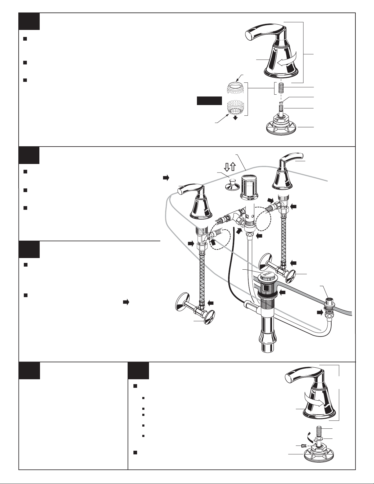
INSTALL HANDLES
Push ADAPTER (1) on VALVE STEM (2), so that the hole of the
ADAPTER (1) without a spline is facing up. Fig. A. Tighten
STEM SCREW (3) to secure ADAPTER (1).
Find correct position of LEVER HANDLE ASSEMBLY (4) by adjusting
male teeth on ADAPTER (1) to female teeth in HANDLE (4).
Thread LEVER HANDLE ASSEMBLY (4) onto DECK ADAPTER (5)
until snug against mounting surface.
Fig. A.
TOP
THREAD ON
4
TO DECK
ADAPTER
1
3
2
12
13
TEST INSTALLED FITTING
With HANDLES (1) in OFF position, turn on WATER
SUPPLIES (2) and check all connections for leaks.
Operate both HANDLES (1) to flush water
lines thoroughly.
Rotate TRANSFER VALVE (5) from rim wash to
spray several times to check operation.
CHECK DRAIN CONNECTIONS
Pull up POP-UP KNOB (3) and fill Bidet with water. Check
that DRAIN STOPPER (4) makes a good seal and retains
water in Bidet. If STOPPER (4) does not seal properly,
please refer to “Troubleshooting Guide” in these instructions.
Push POP-UP KNOB (3) down and check all drain
connections and "P" trap for leaks. Tighten
if necessary.
SPLINE END DOWN
OUTLINE OF BIDET
1
5
1
3
4
2
SPRAY
14
Care Instructions
American Standard’s EverClean
finish will wipe clean with a soft,
dry cloth.
A soft cloth with clean water
may also be used, if desired.
No additional cleaning products
are required.
DO NOT USE: Soaps, acid,
polish, abrasives, harsh
cleaners, or a cloth with a
coarse surface.
EverClean™ Finish
2
15
SERVICE
To change direction of handle rotation,
proceed as follows:
Turn valve to OFF position. Unthread HANDLE
BASE (1) from DECK ADAPTER (2).
Pull HANDLE ASSEMBLY off VALVE STEM (3).
Remove SPRING CLIP (4). Lift STOP WASHER (5),
turn 90˚ and replace. Replace SPRING CLIP (4).
Find correct position of HANDLE ASSEMBLY by adjusting
male teeth on VALVE STEM (3) to female teeth in HANDLE.
Thread HANDLE ASSEMBLY onto DECK ADAPTER (2)
until snug against mounting surface.
If spout drips, operate handles several times from
OFF to ON position. Do not force - handles turn
only 90˚.
4
UNTHREAD
1
4
2
90˚
HANDLE
ASSEMBLY
3
5
M968893
 Loading...