

American Standard 7025.1, 7025.2, 702B.2, 7025.3, 702B.1 Installation Instructions Manual
...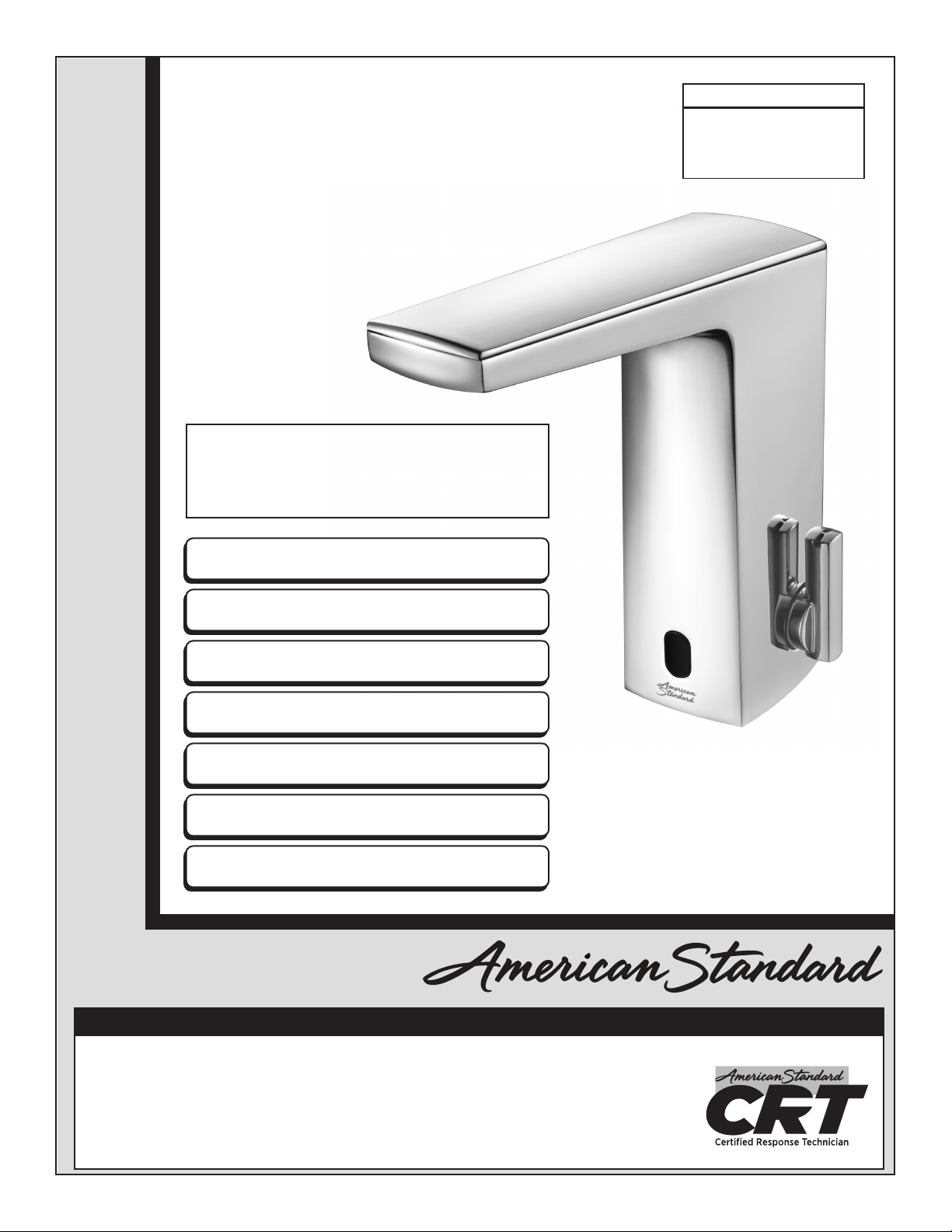
Paradigm™ Selectronic® Integrated
Faucet with Optional Above-Deck Mixing
& SmarTherm
CAUTION: Use only American Standard supplied
transformers and cable sets. Using non-AS supplied
cables, or cutting, splicing or modifying any components
will void the warranty.
®
MODEL NUMBERS
7025.1xx 702B.1xx
7025.2xx 702B.2xx
7025.3xx 702B.3xx
Product No’.s & Options 2
Specications 3
Faucet Installation 3
Electrical Installation 4-5
Start-up / Maintenance 6-8
FAQ’s / Troubleshooting 9
Parts 10
Installation Instructions
Certied to comply with ASME A112.18.1
© 2018 AS America, Inc.
NOTE TO INSTALLER: Please give this manual to the customer after installation.
To learn more about American Standard Selectronic® Products visit our website at: www.americanstandard-us.com
or e-mail us at: CRTTEAM@lixilamericas.com
For Parts, Service, Warranty or other Assistance,
please call (844) CRT-TEAM / (844) 278-8326 (In Canada: 1-800-387-0369)
(In Toronto Area only: 1-905-306-1093)
© 2018 AS America Inc.
1
M965985 (11/18)
Thank you for selecting American-Standard...the benchmark of ne quality for over 100 years. To ensure that your
installation proceeds smoothly--please read these instructions carefully before you begin.
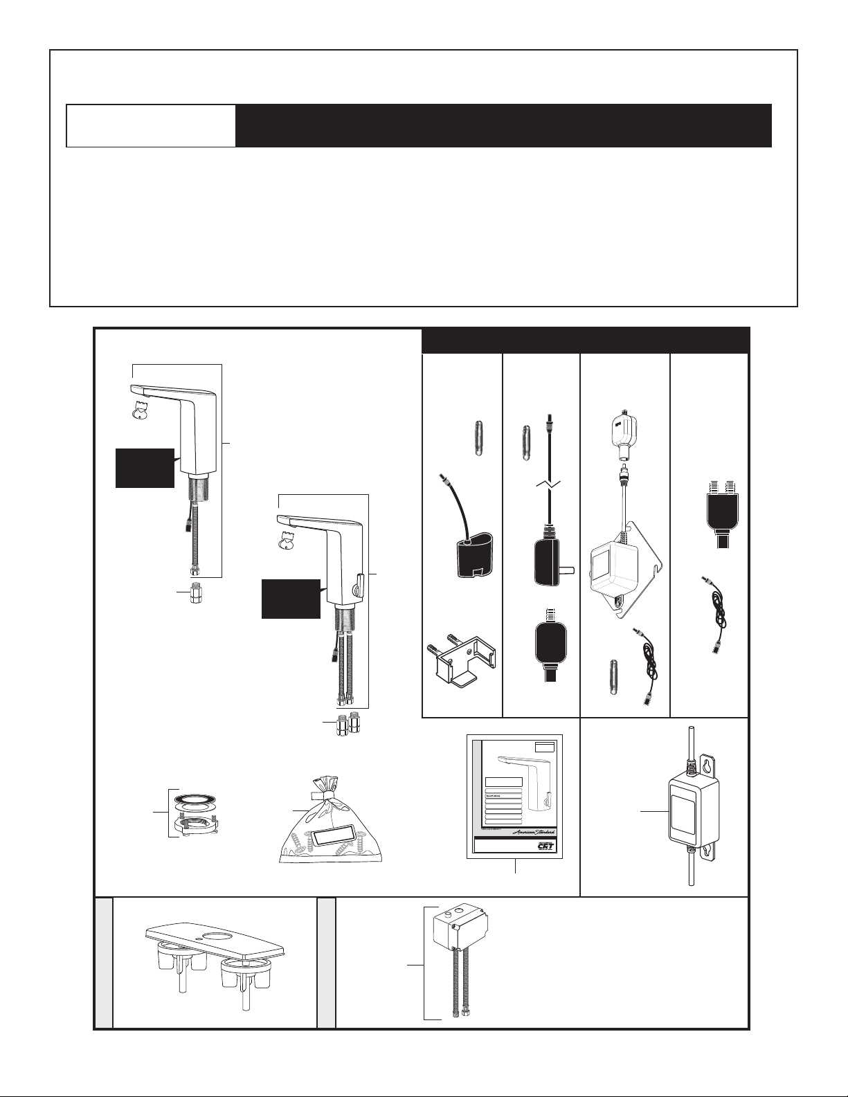
UNPACKING
Remove the tting and loose items from the carton. The illustration below shows all the ttings and loose items after they
have been removed from the carton. Some items may be packaged partially assembled to other items.
1. Installation Instructions
2. Paradigm Spout Assembly (less mixing)
2a. Paradigm Spout Assembly (mixing)
3. Mounting Kit
DO NOT REMOVE
PROTECTIVE
FILM FROM
SENSOR EYE UNTIL
INSTALLATION IS
COMPLETE.
Some Residual Water May Remain In The Valve During Shipping.
4. Thermostatic Mixing Valve (optional, must be ordered separately)
5. Inline Filter/Check Valve Assembly
6. Assembly Parts
7. Battery Back-Up Unit (optional, must be ordered separately)
POWER KITS SOLD SEPARATELY
PWRX
Power Kit
Plug-In AC
Power Kit
PK00. PA CPK00.WRK
2
Hard-Wired AC
Power Kit
PK00.HAC PK00.MAC
Multi-AC
Power Kit
All American Standard Products Are Water Tested At Our Factory.
DO NOT REMOVE
5
PROTECTIVE
FILM FROM
SENSOR EYE UNTIL
INSTALLATION IS
COMPLETE.
5
3
Deck Plate
6
Mixing Valve
2a
605XTMV1070
®
3
(In Toronto Area only: 1-905-306-1093)
MODEL NUMBERS
7025.1xx 702B.1xx
7025.2xx 702B.2xx
7025.3xx 702B.3xx
1
Paradigm Integrated Faucet
with Optional Above-Deck
Mixing & SmarTherm
CAUTION: Use only American Standard supplied
transformers and cable sets. Using non-AS supplied
cables, or cutting, splicing or modifying any components
will void the warranty.
Product No’.s & Options 2
Faucet Installation 3
Electrical Installation 4-5
Start-up / Maintenance 6-8
FAQ’s / Troubleshooting 9
Parts 10
Inst all ati on Instr uctions
© 2018 AS America, Inc.
NOTE TO INSTALLER: Please give this manual to the customer after installation.
To learn more about American Standard Selectronic® Products visit our website at: www.americanstandard-us.com
or e-mail us at: CRTTEAM@americanstandard.com
For Parts, Service, Warranty or other Assistance,
please call (844) CRT-TEAM / (844) 278-8326 (In Canada: 1-800-387-0369)
© 2018 AS America Inc.
1
Battery
Back-Up
Kit
7
M965985 (11/18)
PK00.BBU
4
702P.400
Paradigm 4"
2
M965985 (11/18)
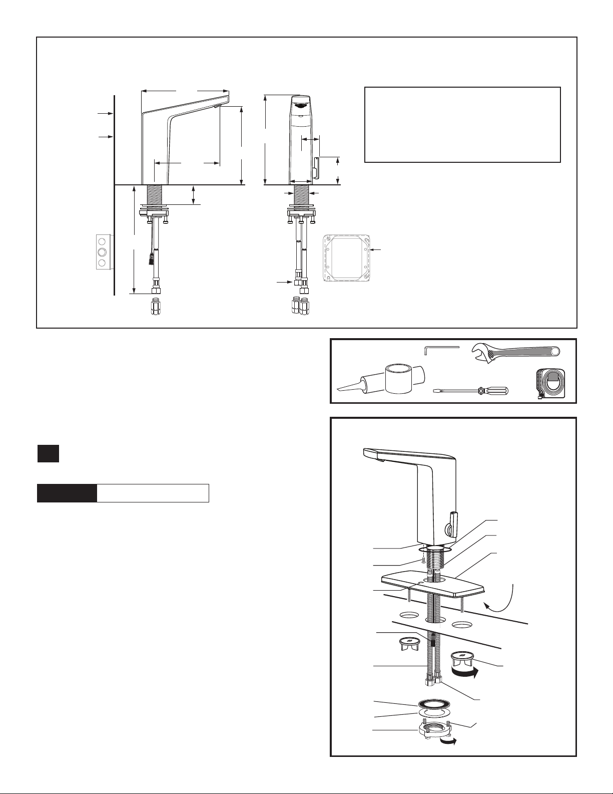
Paradigm
Roughing-in Dimensions
189 mm
(7-1/2")
FINISHED WALL
OR BACKSPLASH
CLEARANCE
25 mm (min)
(1" min)
140 mm
(5-1/2")
38 mm
(1-1/2")
597 mm
(23-1/2")
192 mm
(7-1/2")
169 mm
(6-5/8")
3/8" COMPRESSION
CONNECTORS
51 mm
(2")
39 mm
(1-1/2")
59 mm
(2-3/8")
28 mm
(Ø1-1/8")
Note: All plumbing and electrical wiring must be installed in
accordance with applicable codes, regulations and standards.
CAUTION: Use only American Standard
supplied transformers and cable sets.
Using non-AS supplied cables, or cutting,
splicing or modifying any components
will void the warranty.
RECOMENDED CONTROL BOX OR
EQUIVALENT BY OTHERS
4" (102mm) SQ. X 2-1/2" (64mm) DEEP 2-GANG ELECTRICAL
BOX Appleton #4SD1 OR EQUAL (BY OTHERS).
(Used with Hard-Wired AC Transformer)
RECOMMENDED TOOLS
1. 2.5 mm Hex Wrench (Included)
2. Adjustable Wrench
3. Plumbers’ Putty or Caulking
4. Flat Blade Screwdriver
5. Tape Measure
SPOUT ASSEMBLY INSTALLATION;
1
Fig. 1
CAUTION
1. Make sure O-RING (1) is installed in spout base.
IMPORTANT: Do not use putty when installing faucet
without escutcheon.
2. If installing DECK PLATE (2) (optional): Apply a bead
of putty to bottom edge of PUTTY PLATE (2). Install
SCREW (11) into the MOUNTING BASE OF THE
FAUCET (13) and allign SCREW (11) with HOLE (12).
3. Insert SUPPLY HOSES (3), SHANK (4) and SENSOR
CABLE (5) (only included in base model) through hole
in DECK PLATE with PUTTY PLATE (2) and mounting
surface.
Turn off hot and cold water
supplies before beginning
Fig. 2
3
Fig. 1
13
11
12
1
2
4
I
MPORTANT: Do not
use putty when installing
faucet without escutcheon.
5
10'
1
4
(OPTIONAL)
2
PUTTY
(If required)
5
MOUNTING
SURFACE
4. Assemble RUBBER WASHER (7), BRASS WASHER (8)
and THREADED LOCKNUT (9) onto SHANK (4) from
underside of sink or mounting surface. Hand tighten
LOCKNUT (9).
5. Use a screwdriver to tighten SCREWS (10) on
LOCKNUT (9). Work your way around LOCKNUT (9),
tightening the screws slightly each time until all are
snug to ensure even pressure.
3
3
7
8
TIGHTEN
SPIN NUTS
MPORTANT: Do not
I
use sealent on threads
10
9
M965985 (11/18)
 Loading...