

Page 1
INSTALLATION INSTRUCTIONS
CARE AND MAINTENANCE
0641 BOULEVARD
0403 TROPIC PETITE
0404 TROPIC GRANDE
Thank you for selecting American Standard - the benchmark of fine quality for over 100 years. To ensure this
product is installed properly, please read these instructions carefully before you begin. (Certain installations may
require professional help.) Also be sure your installation conforms to local codes.
CAUTION: PRODUCT IS FRAGILE. TO AVOID BREAKAGE AND POSSIBLE INJURY HANDLE WITH CARE!
!
NOTE: Pictures may not exactly define contour of china and components.
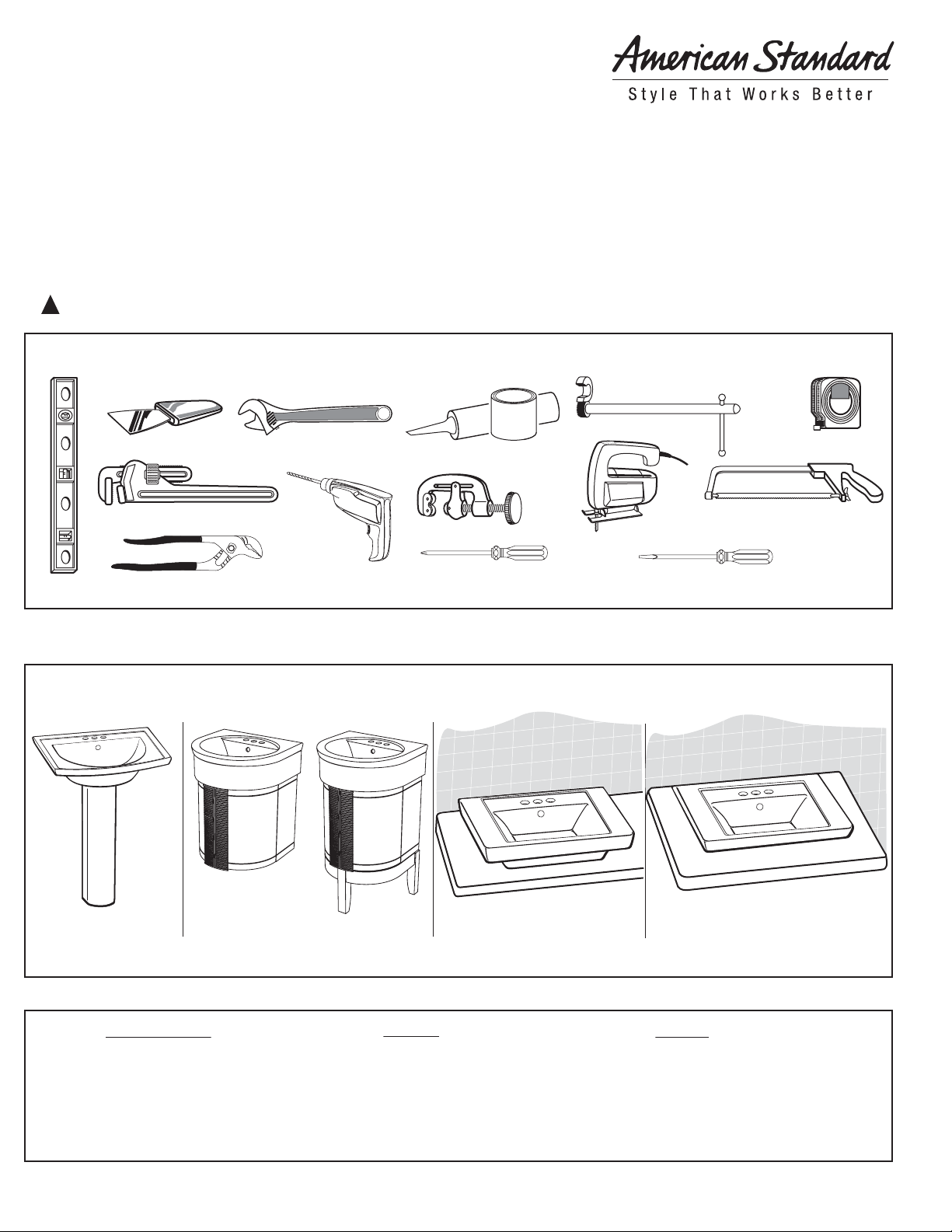
Recommended Tools & Materials
Level
Putty Knife
Pipe Wrench
Channel Lock Pliers
Adjustable Wrench
Drill
Plumbers' Putty or
Caulking
Tubing Cutter
Phillips Screwdriver
Basin Wrench
Saber Saw
Regular Screwdriver
Tape
Measure
Hacksaw
OBSERVE LOCAL PLUMBING AND BUILDING CODES
This lavatory can be installed 4 different ways. Please follow the instructions for your installation method.
SAVE FOR FUTURE USE
1. PEDESTAL 2. WALL-HUNG ON FURNITURE
In the United States:
American Standard Brands
P.O. Box 6820
Piscataway, New Jersey 08855
Attention: Director of Consumer Affairs
For residents of the United States, warranty
information may also be obtained by calling
the following toll free number: (800) 442-1902
www.americanstandard-us.com
Product names listed herein are trademarks of AS America, Inc.
© AS America, Inc. 2009
2480 Stanfield Rd.
Mississauga, Ontario
Canada L4Y 1S2
Toll Free: (800) 387-0369
www.americanstandard.ca
In Canada:
AS Canada ULC
3. ABOVE COUNTER 4. DROP-IN
not recommended for 0404
*
Customer Service Manager
AS Maquila, S.A. de C.V.
Ecatepec 55540 Edo. Mexico
www.americanstandard.com/mx
not recommended for 0404
*
In Mexico:
Via Morelos #330
Col. Santa Clara
7301354-100 Rev. B
Page 2
1. Pedestal installation
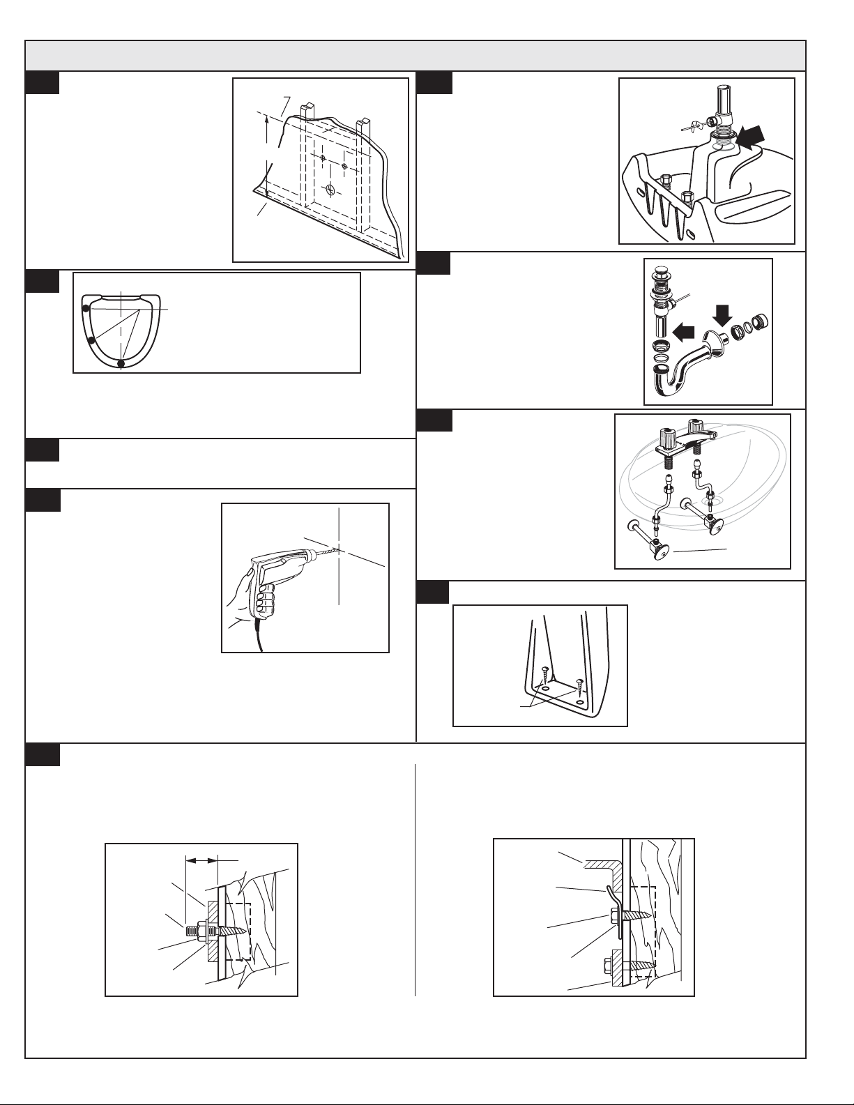
1-A
Provide suitable reinforcement
behind finished wall for lavatory
mounting screws.
C/L of 2X6
Support
*
Determine horizontal center line
*
location of support from fixture.
NOTE: If replacing an existing sink
be certain to shut off water supply
before removing old sink.
1-B
Place lavatory and pedestal into installed position. Level and
square the lavatory and pedestal assembly. Use one or more
bumper cushions to level and cushion lavatory slab to pedestal.
1-C
Top of Pedestal
Approx. Bumper locations to
raise the lavatory slab left side.
For example only
Mark lavatory and pedestal screw locations through
the mounting holes.
Finished
Floor
1-D
Remove lavatory and
pedestal from installed
position. Drill pilot holes for
lavatory and pedestal
anchor screws or lag bolts.
1-F
Following manufacturer's
instructions, install faucet and
drain assembly (not included). Be
certain to apply a bead of sealing
putty on the underside of the drain
(area "A") in order to ensure a
watertight seal between the
lavatory and drain. Remove
excess putty after installing
drain on lavatory.
1-G
Return the fitted lavatory to the
installed position. Connect trap to
drain assembly hand tight to check
alignment. It may be necessary to
cut off part of the tailpiece (area
"B") or part of the horizontal leg of
the trap (area "C").
1-H
Secure lavatory to wall as
shown in 1E. Install washers
and hand tighten nuts or lag
bolts. Level and square the
unit. Connect hot and cold
supply lines to the shut-off
valves. Tighten trap joints for
watertight assembly.
1-I
Rear
View
A
C
B
Shut-Off
Valves
Install pedestal screws.
Securely tighten lavatory
anchor nuts or lag bolts.
Note: Some models are supplied with lag bolts, anchor screws,
or steel hangers for lavatory installations only. Other models and
all pedestals are not provided with mounting hardware. Various
pedestal screw sizes and types are available to the installer at
local hardware outlets.
1-E
ANCHOR SCREW INSTALLATION
Install lavatory anchor screws
leaving 1-7/8" threaded end
exposed as illustrated.
1-7/8"
Lavatory
Anchor
Screw
Nut
Washer
IMPORTANT: Final assembly of nut and washer or lag bolt method shown for reference only.
Pedestal
Screws
LAG BOLT INSTALLATION
Use lag bolts to secure
lavatory as illustrated.
Lavatory
Steel
Hanger
Lag
Bolt
Washer
Lavatory
Note: Space constraints
may dictate method of
fastening pedestal to floor.
2
7301354-100 Rev. B
Page 3
2. Wall-hung on furniture
2-A
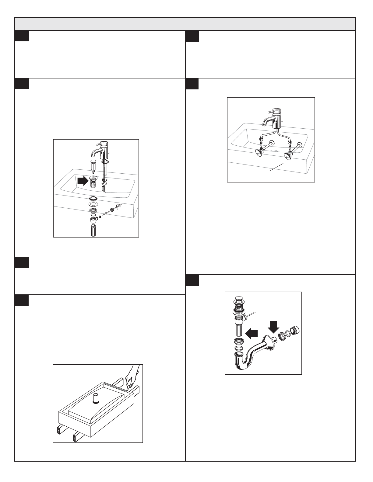
Mounting on Furniture:
Assemble vanity as per instructions.
2-B
Mount the faucet and drain assembly (not included) on
the sink following the manufacturer’s instructions. Be
certain to apply a bead of sealing putty on the
underside of the drain (Part “A”) in order to ensure a
watertight seal between the sink and drain. Remove
excess putty after installing drain on sink.
A
2-E
Use the mounting holes on the rear of the lavatory
to secure the sink to the wall.
2-F
Shut-Off Valves
Connect supply line to faucet (finger tight) and
carefully bend tubes to engage with the
supply shut-off valves. Tighten connections at
faucet and shut-off valves for secure seal.
2-C
Vanity Installation:
• Place the sink temporarily on the vanity to
check for alignment and clearance
2-D
After checking fit and alignment, turn sink upside down
and apply a generous portion of silicone adhesive
around the under side of the rim near the edge. Place
sink in position. Wipe off excess adhesive.
2-G
C
B
Connect trap to drain assembly hand tight to
check alignment. It may be necessary to cut
off part of the tailpiece (area “B”) or part of the
horizontal leg of the trap (area “C”). Secure
joints for watertight assembly.
3
7301354-100 Rev. B
Page 4
3. Above Counter OR
4. Drop-in
** BACK OF LAVATORY IS UNGLAZED **
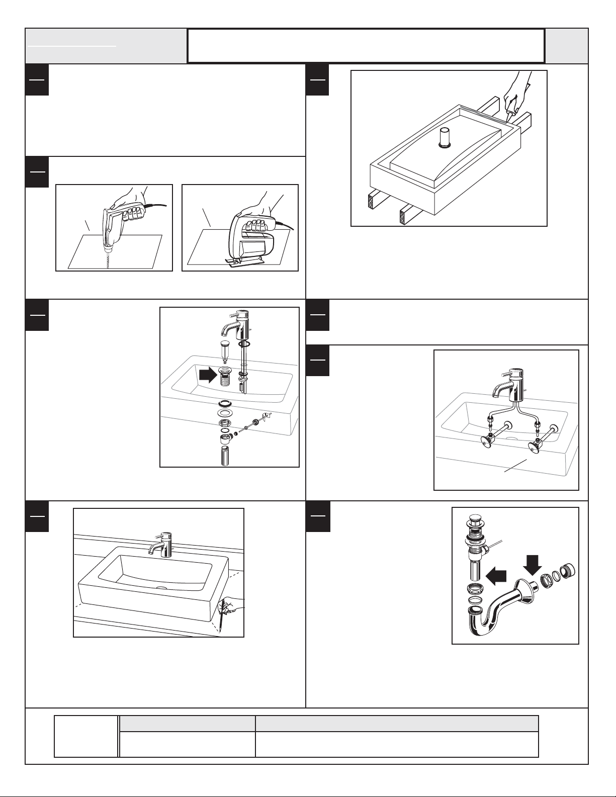
The lavatory must be installed flush with wall.
3-A
Countertop Installation:
4-A
Using the template provided, locate the position of the sink
on the countertop. Provide proper clearance under the
countertop for the faucet supply lines, drain assembly and
the structural parts of the cabinet.
NOTE: If replacing an existing sink be certain to shut off
water supply before removing old sink.
Drill a clearance hole inside the perimeter line of the
3-B
template for countertop installation.
4-B
Perimeter
of
template
Cut opening around the perimeter of the template.
3-C
Mount the faucet and
drain assembly (not
4-C
included) on the sink
following the
manufacturer’s
instructions. Be certain
to apply a bead of
sealing putty on the
underside of the drain
(Part “A”) in order to
ensure a watertight seal
between the sink and
drain. Remove excess
putty after installing
drain on sink.
Perimeter of
template
A
3-E
4-E
After checking fit and alignment, turn sink upside down and
apply a generous portion of silicone adhesive around the
under side of the rim near the edge. Place sink in position.
Wipe off excess adhesive.
3-F
4-F
Use the mounting holes on the rear of the lavatory to
secure the sink to the wall.
3-G
4-G
Connect supply line to faucet
(finger tight) and carefully
bend tubes to engage with
the supply shut-off valves.
Tighten connections at faucet
and shut-off valves for
secure seal.
3-D
4-D
Countertop Installation:
• Place the sink temporarily into the template
• Check for alignment and clearance
• Mark the sink and countertop in several
places as a guide for the installation location.
REPAIR
PARTS
LIST
Part #
047523-0070A Wall mounting kit
3-H
4-H
Connect trap to drain assembly
hand tight to check alignment. It
may be necessary to cut off part
of the tailpiece (area “B”) or part
of the horizontal leg of the trap
(area “C”). Secure joints for
watertight assembly.
Description
Shut-Off Valves
C
B
4
7301354-100 Rev. B
 Loading...