

Installation
Instructions
8AHJE
5F=
Designer Shower
Massage System
Thank you for selecting American-Standard...the benchmark of
fine quality for over 100 years.
To ensure that your installation proceeds smoothly--please
read these instructions carefully before you begin.
™
6035
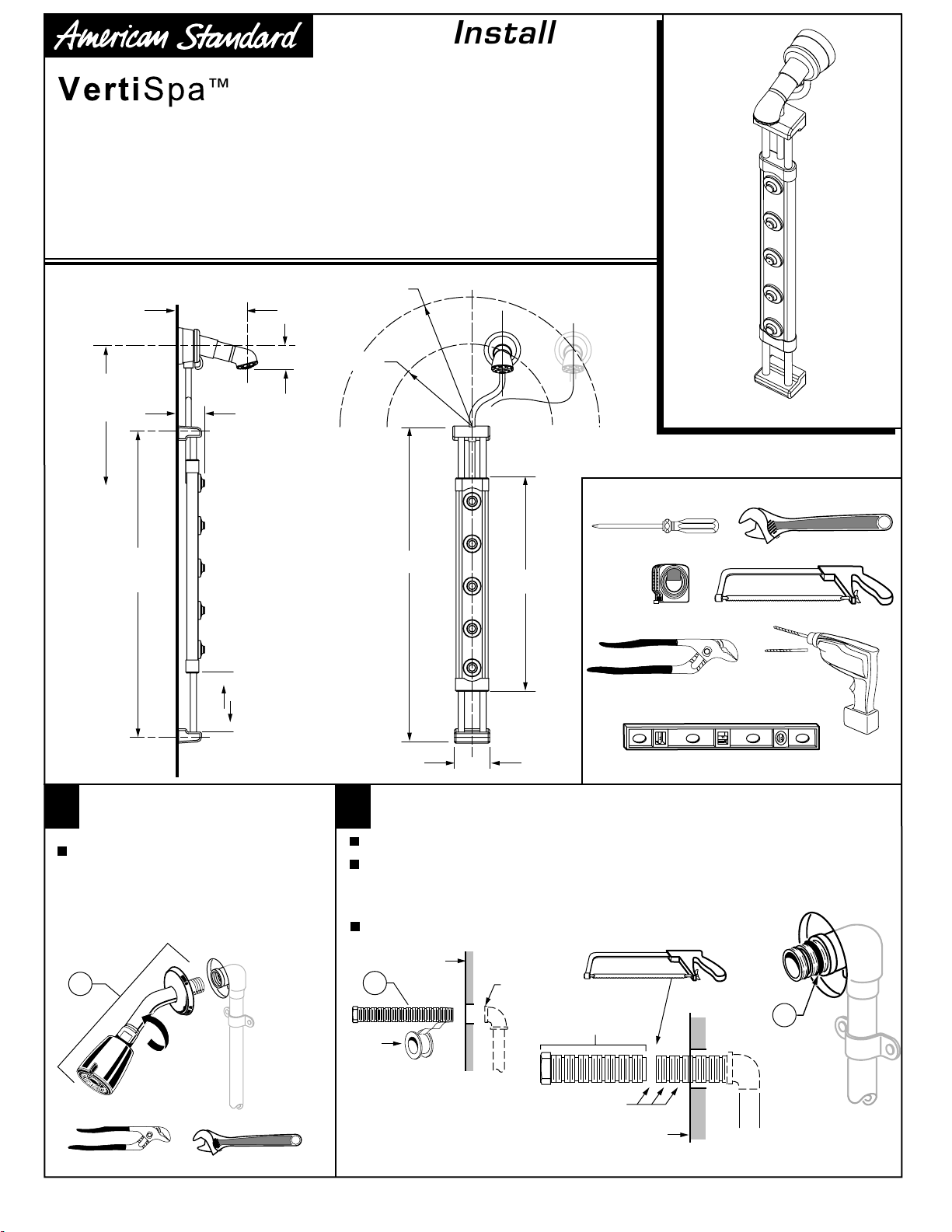
ROUGHING-IN DIMENSIONS
8-5/8"
65" TO 78"
TO FINISHED FLOOR
(OPTIONAL)
37-5/16"
MTG. HOLE
REFERENCE
3"
3-5/8"
9-3/4"
UP AND DOWN
ADJUSTMENT
11-3/4 MAX."
6-1/4 MIN."
38-1/8"
25-7/8"
Certified to comply with ANSI A112.18.1M
M968416 REV 1.1
Tools required for installation:
Phillips Screwdriver
Tape
Measure
Channel Locks
10'
Adjustable Wrench
Hacksaw
5/16"
Drill Bit
Drill
REMOVE EXISTING
1
SHOWER HEAD
Using an adjustable wrench or channel
locks, remove the existing Shower Head,
Arm and Flange (1) by turning
counter-clockwise.
1
Channel Locks
Adjustable Wrench
4-3/8"
INSTALL PIPE NIPPLE
2
Figure 1.
Figure 2.
and tighten. Then, using a hacksaw, cut off excess PIPE NIPPLE (1) at the 3rd
groove from the finished wall. Discard the excess pipe and remove any burrs and
debris from the nipple.
Figure 3
O-RING (2) is provided in parts bag.
FINISHED WALL
1
Teflon
Tape
Figure 1
Apply Teflon tape (provided) to the end of the PIPE NIPPLE (1).
Thread PIPE NIPPLE (1) into elbow fitting, using adjustable wrench
. Install O-RING (2) into groove next to finished wall. One extra
1/2" NPT
Figure 2
EXCESS PIPE
MAKE CUT AT 3rd
GROOVE FROM
FINISHED WALL
NIPPLE
Hacksaw
FINISHED
WALL
123
Level
2
Figure 3
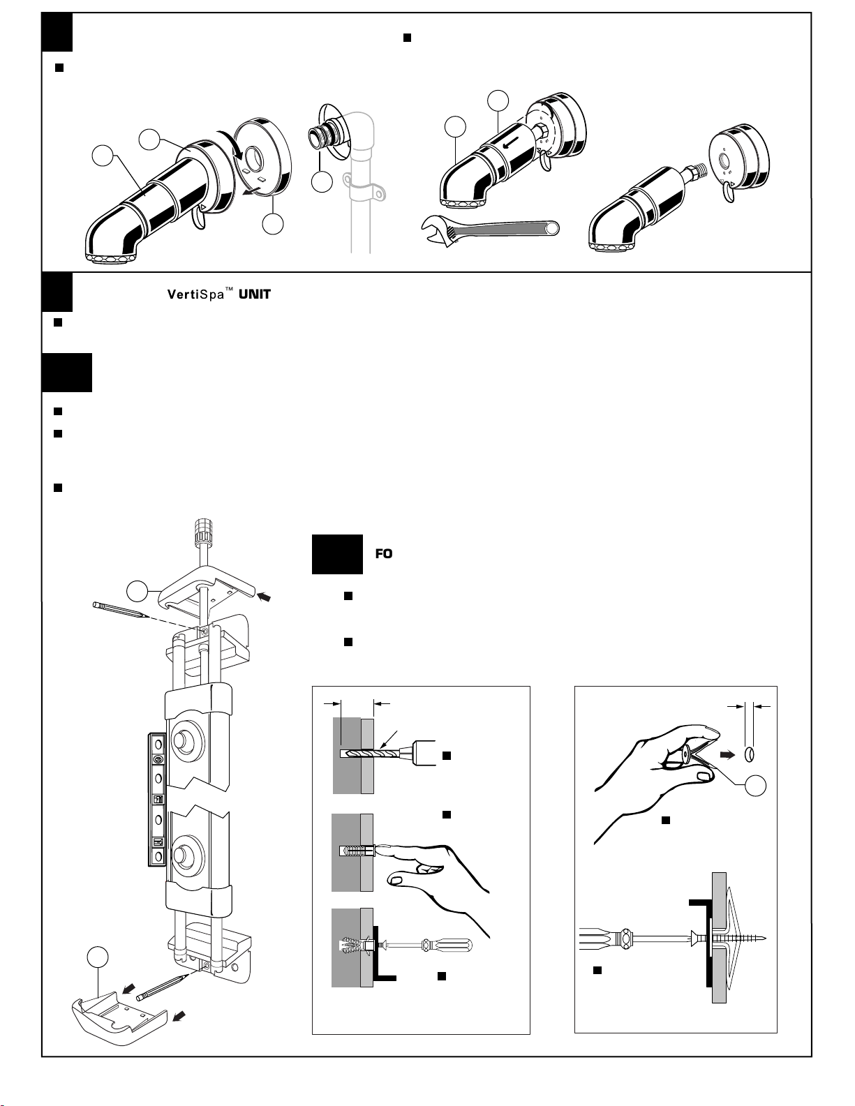
INSTALL DIVERTER WITH SHOWER HEAD
3
Ensure ESCUTCHEON (1) is assembled onto DIVERTER (2).
Hold DIVERTER BODY (2) and thread the DIVERTER (2)
with SHOWER HEAD (3) onto NIPPLE (4) until snug against
the finished wall and in position as shown.
(NOTE: If customer desires to use alternate shower head, then pull
back Escutcheon (1) on SHOWER HEAD (2) and turn counter-clockwise
with an adjustable wrench. Replace with customer shower head,
arm and flange.)
1
2
2
3
4
1
Adjustable Wrench
INSTALL the
4
Remove END CAPS (1) from the two ends by sliding forward over the detents as arrows show in illustration. Locate the unit vertically on
the shower wall in the desired position. (Do not mount the unit closer than 6-1/4" (160mm) or further than 11-3/4" (300mm) from
the DIVERTER.
4a
FOR TILE, CORIAN® OR MARBLE/GRANITE WALL INSTALLATIONS
Note: For granite (Marble) wall Installations use of a hammer drill is suggested.
Figure 1
Mark location of the upper mounting hole. Using a 3/16" carbide drill bit (provided), drill the mounting hole into the shower wall and
install hardware, (See Figure 2). (Caution: Take care when drilling between the Diverter and the valves as water pipes maybe located here).
Mount the unit with screw provided and set the unit vertical using a level. Now mark the lower mounting hole. Remove or swing aside the
unit, drill lower mounting hole and install hardware into mounting hole.
Use mounting screw provided to secure lower section of unit. Slide END CAPS (1) back into position.
. Hold Vertispa unit in desired location. Refer to roughing-in dimensions.
8AHJE
5F=™ UNIT
SHOWER HEAD
REMOVED
Figure 1
1
4b
1
FOR THIN WALL INSTALLATIONS
Figure 3
holes as detailed above. (Caution: Take care when drilling between the Diverter
and the Valves as water pipes may be located here.)
Insert two TOGGLE ANCHORS (1) and secure unit using the two screws provided.
. Use 5/16" standard drill bit (not provided) and drill two mounting
1-1/4" DEEP
3/16" CARBIDE DRILL
DRILL
MOUNTING
HOLE
5/16"
1
Figure 2
PUSH RIBBED
ANCHORS IN
MOUNTING
HOLE
MOUNT UNIT
WITH SCREWS
PROVIDED
MOUNT UNIT
WITH SCREWS
PROVIDED
SQUEEZE ENDS
TOGETHER AND
INSTALL INTO
MOUNTING HOLES.
Figure 3
M968416 REV 1.1

CONNECT FLEXIBLE HOSE TO DIVERTER
5
6
OPERATION
Thread the HOSE COUPLING (1) onto DIVERTER
NIPPLE (2) and hand tighten clockwise. Note: Moulded
end of HOSE COUPLING (1) creates watertight seal with
with thread of DIVERTER NIPPLE (2), so seal washer is
not required.
Make sure HOSE (3) is not kinked or twisted.
2
1
3
SPRAY UNIT (1) can be adjusted up
and down by sliding unit along the
rails. (See Maintenance section for
steps to adjust the tension of SPRAY
UNIT (1) on the rails.)
Shower function can be diverted by
rotating DIVERTER ARM (2) clockwise
for flow out of SPRAYS (3) and counterclockwise for flow out of
SHOWER HEAD (4).
SHOWER HEAD SPRAY (5) can be
adjusted by rotating outer ring on
the faceplate.
2
5
4
9-3/4"
UP AND DOWN
TRAVEL OF UNIT
31
MAINTENANCE
7
Removing spray for cleaning or changing spray location
Figure 1.
by twisting 1/8th of a turn counter-clockwise.
Remove the O-RING (4) and NOZZLE (3).
Nozzle (3) can be cleaned using soft bristled brush.
Replace O-RING (4) and NOZZLE (3) and lock the TRIM (2) into place by
twisting it clockwise until it clicks.
COUNTER-CLOCKWISE
TO REMOVE
Unscrew the TRIM RING (2) on the outside of the SPRAY HEADS (1)
2
4 3
Figure 1
1
CLOCKWISE
TO INSTALL
6
Adjusting tension of SPRAY UNIT on vertical rails.
Shower system comes with two FRICTION CLIPS (5)
installed.
Move SPRAY UNIT (6) up and down along vertical
rails. FRICTION CLIP (5) holds the SPRAY UNIT (6)
at desired location.
(Figure 2)
vertical rails, then remove one FRICTION CLIP (5) or
reposition the CLIPS (5) closer to the center of the
unit. (Note: Tension on vertical rails will reduce when
shower system is moistened from shower application.)
(Figure 3)
groove of FRICTION CLIP (5) onto inside edge of
SPRAY UNIT (6). Rotate other end down and press
until the FRICTION CLIP (5) snaps into position onto
tab of SPRAY BODY (7).
If SPRAY UNIT (6) has too much tension on
5
To replace FRICTION CLIP (5), insert
Figure 2
Figure 3
7
CARE INSTRUCTIONS:
8
5
DO: SIMPLY RINSE THE PRODUCT
CLEAN WITH CLEAR WATER. DRY
WITH A SOFT COTTON FLANNEL
CLOTH.
DO NOT: CLEAN THE PRODUCT WITH
SOAPS, ACID, POLISH, ABRASIVES,
HARSH CLEANERS, OR A CLOTH
WITH A COARSE SURFACE.
Product names listed herein are trademarks of American Standard Inc.
©American Standard Inc. 2004
GROOVE
5
6
TAB
VERTICAL RAILS
For toll-free information and answers to your questions, call:
Weekdays 8:00 a.m. to 7:00 p.m. Eastern Time
IN CANADA 1-800-387-0369 (TORONTO 1-905-306-1093)
HOT LINE FOR HELP
1 (800) 442-1902
M968416 REV 1.1

8AHJE
5F=
™
Designer Shower
Massage System
M950130-YYY0A
SHOWER HEAD
Replace the "YYY" with
appropriate finish code
CHROME 002
M907526-YYY0A
ESCUTCHEON
M950120-YYY0A
DIVERTER UNIT
MODEL NUMBER
6035
M912119-0070A
O-RING
M923107-0070A
PIPE NIPPLE
M962290-YYY0A
SPRAY TRIM KIT
M962291-0070A
SPRAY NOZZLES KIT
M923112-YYY0A
END CAP
M962292-0070A
MOUNTING KIT
- SCREWS (2)
- ANCHOR (2)
- TOGGLE ANCHOR (2)
- DRILL BIT (1)
- TEFLON TAPE (1)
M923106-0070A
FRICTION CLIP
M968416 REV 1.1
 Loading...