

American Standard 50A50-405, 50A50-406, 50A50-471, 50A50-472, 50A50-473 Operation Manual
...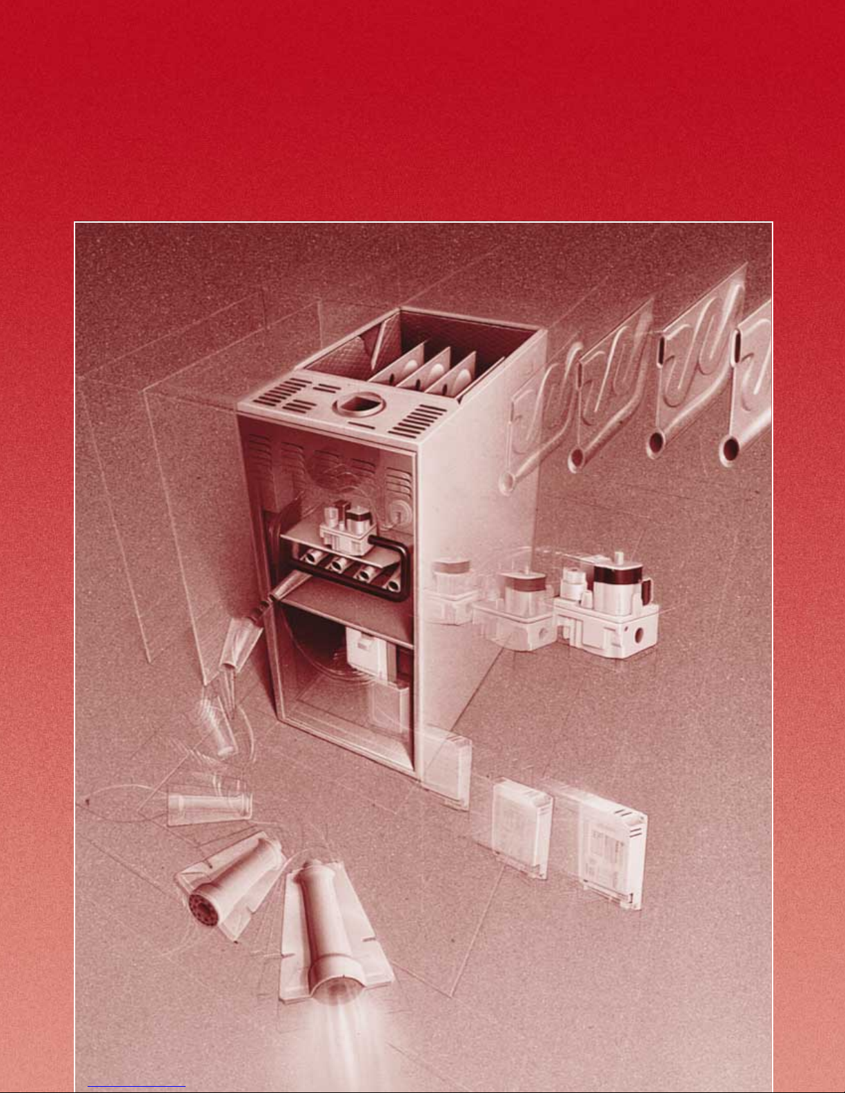
40” Residential Gas
40” Residential Gas
Furnace Operation
Furnace Operation
© American Standard Inc. 1999
© American Standard Inc. 1999
• Model Evolution/Nomenclature
• Model Evolution/Nomenclature
• Heating Sequence of Operation
• Heating Sequence of Operation
• Schematics
• Schematics
• Ignition Systems
• Ignition Systems
• Service/Troubleshooting
• Service/Troubleshooting
1

Preface
Air Conditioning and heating service technicians
must have a working knowledge of basic electrical and
refrigeration service procedures. In order to service
gas furnaces, a thorough understanding of the units
sequence of operation is essential. This publication is
based on White-Rogers controls and provides the
narrative and schematic drawingsnecessary to
provide this understanding for thesefurnaces. Also
included is a description of operating principles of
different ignition systems.
Contents
Model Evolution .......................................................................................................................................................... 3
Model Nomenclature .................................................................................................................................................. 4
Component Identification – ✽UD/✽DD-R Models ...................................................................................................... 5
Component Identification – ✽UY/✽DY-R Models ....................................................................................................... 6
Integrated Furnace Controls (I.F.C.) ............................................................................................................................ 7
Self Diagnostic Features 50A50 and 50A51 ............................................................................................................... 9
Integrated Furnace Control Timing ............................................................................................................................ 10
Abnormal Furnace Operation – 50A50 and 50A51 .................................................................................................... 11
Single Stage 50A50 Sequence of Operation.............................................................................................................. 14
Wiring Schematic – Single Stage 50A50 Integrated Furnace Control ...................................................................... 15
Two Stage 50A51-405 Sequence of Operation .......................................................................................................... 16
Wiring Schematic – Two Stage Heat 50A51-405 Integrated Furnace Control ......................................................... 17
Two Stage Variable Speed Sequence Of Operation .................................................................................................. 18
Wiring Schematic – Two Stage Variable Speed 50A51-505/50A51-506 Integrated Furnace Control ..................... 19
Integrated Control Quick Reference ........................................................................................................................... 20
Furnace ECM
TM
ECM
Schematic – Motor Control Board .............................................................................................................................. 24
Flame Rectification Principle – Measurement ........................................................................................................... 25
Flame Current Tester/Simulator ................................................................................................................................. 26
Combustion Air Pressure Switch Check – Measurement ......................................................................................... 27
Furnace Pressure Switch Settings .............................................................................................................................. 28
Gas Valves .................................................................................................................................................................... 29
✽ Models maybe an A or T or F continued
TM
2 Motor Operation ............................................................................................................................. 21
2 Variable Speed Furnace Motor Quick Check ............................................................................................... 22
Note: This publication is general in nature and is intended for
INSTRUCTIONAL PURPOSES ONLY. It is not to be used for
equipment selection, application, installation, or specific service
procedures.
1

Contents
Manifold Pressure Settings ......................................................................................................................................... 31
Direct Vent Manifold Pressure Check ......................................................................................................................... 32
Determining Natural Gas Furnace Input .................................................................................................................... 33
Single Stage Twinning Kit ........................................................................................................................................... 34
Field Wiring Diagrams – Single Stage and Two Stage Thermostats ....................................................................... 35
Two Stage Twinning Kit .............................................................................................................................................. 36
Fields Wiring Diagram – Twinning ✽UD-R Furnaces ................................................................................................. 37
Single Wire Twinning – For Models with Twin Terminals ......................................................................................... 38
Radiant Sense Ignition Controls ................................................................................................................................. 39
Identifying Radiant Sense Controls ............................................................................................................................ 40
Radiant Energy Sensor................................................................................................................................................ 41
50A52-100 Sequence of Operation ............................................................................................................................. 42
Wiring Schematic – Version 1 Radiant Sense Control .............................................................................................. 43
50A52-100 Sequence of Operation ............................................................................................................................. 44
Wiring Schematic – Version 2 Radiant Sense Control .............................................................................................. 45
– continued
50A52-100 Sequence of Operation ............................................................................................................................. 46
Wiring Schematic – Version 3 Radiant Sense Control .............................................................................................. 47
50A52-100/101/102 Sequence of Operation ............................................................................................................... 48
Wiring Schematic – Version 4 Radiant Sense Control .............................................................................................. 49
Troubleshooting Procedures ....................................................................................................................................... 50
• 50A50 Flow Chart 1 ................................................................................................................................................. 51
• 50A50 Flow Chart 2 .................................................................................................................................................. 52
• 50A50 Flow Chart 3 ................................................................................................................................................. 53
• 50A50 Flow Chart 4 ................................................................................................................................................. 54
• 50A50 Flow Chart 5 ................................................................................................................................................. 55
• 50A51 Flow Chart 1 .................................................................................................................................................. 56
• 50A51 Flow Chart 2 .................................................................................................................................................. 57
• 50A51 Flow Chart 3 .................................................................................................................................................. 58
• 50A51 Flow Chart 4 .................................................................................................................................................. 59
• 50A51 Flow Chart 5 .................................................................................................................................................. 60
• 50A52 Flow Chart 1 .................................................................................................................................................. 61
• 50A52 Flow Chart 2 .................................................................................................................................................. 62
• 50A52 Flow Chart 3 .................................................................................................................................................. 63
• 50A52 Flow Chart 4 .................................................................................................................................................. 64
Legends – System Wiring ........................................................................................................................................... 65
✽ Models maybe an A or T or F
2

40" Residential Gas Furnace Evolution
Third Quarter 1991 – ✽UD-R and ✽UD-C 40" induced draft upflow models introduced to replace the TUD-B
linear burner upflow models.
Second Quarter 1992 – ✽DD-R and ✽DD-C 40" induced draft downflow/horizontal models introduced to
replace the TDD-B linear burner downflow models and the THP, THS and THD series
horizontal models.
Second Quarter 1993 – ✽UE 40" single stage radiant sense ignition model introduced.
Third Quarter 1993 – ✽UC-C and ✽DC-C 40" condensing models introduced to replace the TUC-B and TDC-B
linear burner condensing models. (✽UC-C models convert to horizontal left, ✽DD-C
models convert to horizontal right.)
Fourth Quarter 1993 – ✽DE 40" single stage radiant sense ignition models introduced.
Second Quarter 1994 – ✽UX-C and ✽DX-C 40" direct vent condensing models introduced to replace the
✽UX-B and ✽DX-B linear burner direct vent models.
Third Quarter 1994 – TUJ-A 40" radiant sense ignition model introduced. Model converts to horizontal left
or horizontal right and is shipped without bottom panel and filter. Model discontinued
third quarter 1995.
Fourth Quarter 1994 – ✽UY-R-V 40" two-stage, direct vent variable speed condensing models introduced to
replace the TUC/TDC-B-V variable-speed models.
Second Quarter 1995 – ✽DD-C-C Downflow/Horizontal and ✽UD-C-H Upflow/Horizontal models introduced.
Previous upflow models were for upflow applications only. The ✽UD-C-H and TUE-A-H
models are also approved for horizontal installation. The ✽DD-C-C and ✽UD-C-H
models are equiped with the “enhanced” integrated furnace control with 120 VAC
humidifier output, adaptive hot surface ignitor timing and improved fault tolerances.
First Quarter 1996 – TUE/TDE-A-K up graded to 80% AFUE. These models have remote flame rectification
ignition control systems.
Fourth Quarter 1997 – Introduced the Silicon Nitride Ignitor and appropriate controls.
For all models equipped with the Silicon Nitride
Hot Surface Ignitor, see Pub. No. 34-3405.
✽ Models maybe an A or T or F
3

Model Nomenclature
Furnace Configuration
U = Upflow
U = Upflow/Horizontal
D = Downflow/Horizontal
Type
C = Condensing – 90% AFUE
D = Induced Draft – 80% AFUE
E = 78%/80% AFUE
X = Direct Vent Condensing
Y = Direct Vent Condensing Variable-Speed
A =
J =
Heating Input MBTUH
Example: 040 = 40,000 MBTUH
Major Design Change
C = Single Stage
R = Two Stage
78%/80% AFUE Cumberland
}
✽ UC040C924A
1
Power Supply and Fuel
115 Volt
Natural Gas
Airflow Capacity for Cooling
18 = 1 1/2 Tons 42 = 3 1/2 Tons
24 = 2 Tons 48 = 4 Tons
30 = 2 1/2 Tons 60 = 5 Tons
36 = 3 Tons
Example: 24 MBTUH = 2 Tons
400 CFM per Ton
2 Tons x 400 CFM/Ton = 800 CFM
V3 = 2 1/2 – 3 1/2 Tons, Variable Speed Motor
V4 = 3 – 4 Tons, Variable Speed Motor
V5 = 3 – 5 Tons, Variable Speed Motor
Minor Design Change
H = Horizontal (Upflow/Horizontal Models Only)
Product Service Change
Part I.D.
✽ First letter may be A or T or F
4
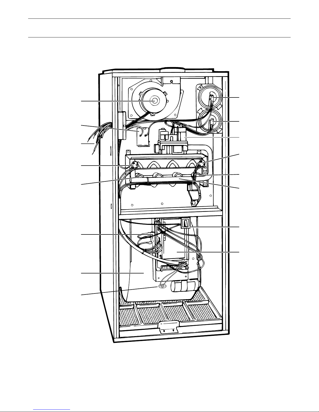
Component Identification – ✽UD/✽DD-R Models
INDUCED DRAFT
BLOWER (2 SPEED)
HIGH TEMPERATURE
LIMIT (TCO)
HIGH VOLTAGE
AND ACCESSORY
HOOK-UP
FLAME ROLL-OUT
MAY BE A FUSE LINK
OR A BIMETAL SWITCH
FLAME SENSOR
TRANSFORMER
1ST STAGE
PRESSURE SWITCH
2ND STAGE
PRESSURE SWITCH
GAS VALVE
(2 STAGE)
FLAME ROLL-OUT
MAY BE A FUSE LINK
OR A BIMETAL SWITCH
HOT SURFACE
IGNITOR
INSHOT BURNER
DOOR SWITCH
DIRECT DRIVE
BLOWER
REVERSE FLOW
SWITCH TCO-B
✽ Models maybe an A or T
INTEGRATED
FURNACE CONTROL
5

Component Identification – ✽UY/✽DY-R Models
HIGH TEMPERATURE
LIMIT SWITCH
BURNER
SIGHT GLASS
ELECTRICAL
JUNCTION BOX
2ND STAGE
PRESSURE SWITCH
1ST STAGE
PRESSURE SWITCH
LINE CHOKE
(NOT ON ALL MODELS)
TRANSFORMER
FLAME ROLL-OUT
SWITCH
(MANUAL RESET)
2 STAGE
GAS VALVE
INDUCED DRAFT
BLOWER
(2 SPEED)
TCO (LIMIT)
DOOR SWITCH
TM
MOTOR
ECM
CONDENSATE
TRAP
✽ Models maybe an A or T
IGNITION
CONTROL
TM
INTERFACE
ECM
BOARD
(MOTOR ONLY)
6

White-Rodgers Integrated Furnace Controls –
50A50 & 50A51 Series
The White-Rodgers Integrated Furnace Control (I.F.C.)
is an automatic ignition control module that uses
microcomputer based circuitry to continuously monitor,
analyze and control the proper operation of the gas
burner, induced draft motor and indoor blower. The
microcomputer provides continuous surveil-lance of
the thermostat, flame sensor and safety devices to
initiate automatic gas burner ignition and shutoff
sequences during normal, or fault condition operation.
There are currently several versions of the White-Rodgers
50A50/50A51 Integrated Furnace Controls:
1. 50A50 Series -405 Single-Stage controls are used in
✽UD/✽DD-C-A, B and FCA/FUA-A-A.
2. 50A50 Series -406 Single-Stage controls are used in
✽UC/✽DC-A & B and ✽UX/✽DX-C-A.
3. 50A50-471 and 473 Single-Stage used in ✽UD-C-H
and ✽DD-C-C.
4. 50A50-472 and 474 Single-Stage used in ✽UC/
✽DC-C-C.
5. 50A50-571 Single-Stage used in ✽UE/✽DE-A-K,
FUA- and FCA-E and is part of the up-grade
control system for Radiant Sense Controls,
Part No. KIT 3793.
6. 50A51 Series -405 or -495 Two-Stage used in
✽UD/✽DD-R.
7. 50A51-506 Two-Stage Variable-Speed used in
✽UD/✽DD-R9V. 50A51-505 superseded by 50A51-506
after October 1995.
8. 50A51-506 Two-Stage Variable-Speed used in
✽UY/✽DY-R9V.
9. 50A51-507 Two-Stage Variable-Speed used on all
Variable-Speed models after September 1996.
✽ First letter may be A or T or F
Note: Control models 50A50-406/472 and 474 and
50A51-405/-495/-505/-506/-507 provide on-board
relay switching of 120V AC system power for the
optional humidifier and electronic air cleaner accessories.
Control models 50A50-471/473 provides on-board
relay switch-ing of system power for the optional
humidifier accessory only.
During heating cycles, the Control provides on-board relay
switching of 120V AC system power for the
induced draft motor, hot surface ignitor and 24V AC power
for the gas valve. During heating and cooling cycles, the
Control provides on-board relay switching of system power
for the indoor blower motor.
Fan On
When the thermostat fan switch is in the ON position,
24V AC is applied from the thermostat “G” terminal
to the I.F.C. Control “G” terminal.
The “G” call to the I.F.C. control will cause it to energize
an internal relay coil. This relay’s switch will close,
energizing the indoor blower.
On single stage controls, the blower will run on
Heating Speed. On Two-Stage I.F.C. controls, the
blower will run on the low Heating Speed. On
Variable-Speed models, the “G” call to the blower
motor will signal it to run at 50% of the programmed
cooling CFM speed.
Cooling Air Flow
When the thermostat system switch is in the COOL
position and the thermostat calls for cooling, 24V AC
is applied from the thermostat “Y” terminal to the
I.F.C. Control “Y” terminal.
The “Y” call to the I.F.C. Control will cause it to
energize an internal relay coil. This relay switch will close
energizing the indoor blower on the cooling speed tap.
The I.F.C. control’s fan speed relays are inter-locked to
prevent power from being applied to two blower motor
speed taps at the same time. On Variable-Speed models,
the “Y” call to the blower motor will signal it to run at
80% of the programmed cooling CFM Speed. Note:
Y and BK must be jumper or humidistat connected to
BK to get 100%.
If the “Y” connection is not made to the Control,
the indoor blower will run on heating speed during a
cooling cycle.
Cooling Blower Delay to Off
The Control provides an optional indoor blower off
delay of 80 seconds in cooling cycles. The off delay is
field selectable by adjusting Dip-Switch 1 to OFF
except 50A50-571 Control. A jumper wire must be cut.
Dip-Switch 1 must be in the ON position always on
variable speed furnace models using 50A51-505/-506/-507
Controls. See Furnace ECM
TM
2 Motor Operation.
7
2
A
White-Rodgers Integrated Furnace Controls –
50A50 & 50A51 Series
Heating Blower On and Off Delay
These controls provide a fixed 45 second indoor “blower
on” delay after the flame is sensed during heating
cycles. After this time delay, the indoor blower
motor will be energized to run on heating speed. The
Control also provides an indoor “blower off” delay.
The 50A50-571 I.F.C. delay to off is not adjustable,
all other 50A50 and 50A51 controls have field
adjustable delays to off. The off delay time is field
selectable by adjusting Dip-Switches 2 and 3 on
the Control.
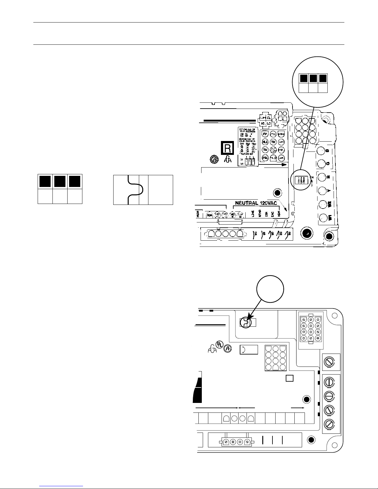
Dip-Switch Settings or Jumper Wire
123
ON
OFF
Cooling Fan Off Delay (seconds)
Switch 1/Jumper ON = 0 (Factory Setting)
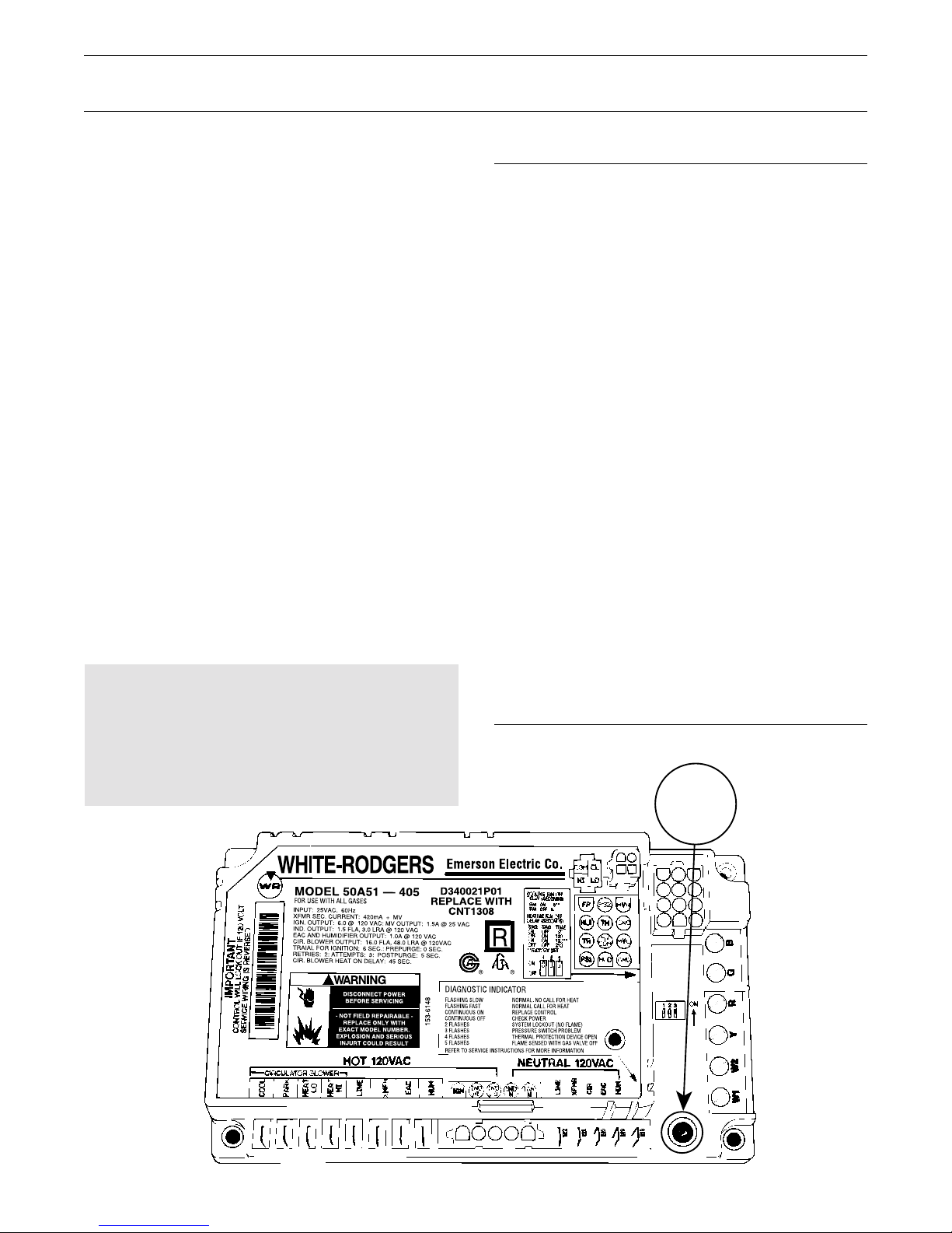
50A51-405 Control
Emerson Electric Co.
S
D340021P01
REPLACE WITH
CNT1308
T
: 1
.5A
@
25
V
A
0 V
@
E
: 0 S
: 5
C
A
C
1
20
V
A
C
E
C
.
S
E
C
.
®®
DIAGNOSTIC INDICATOR
FLASHING SLOW
FLASHING FAST
CONTINU
OU
CO
NTINUOU
153-6148
2 FLASHES
3 FLASHES
4 FLASHES
5 FLASHES
REFER TO SERVICE INSTRUCTIONS FOR MORE INFORMATION
S O
S OFF
N
O
R
M
AL. NO
N
O
R
M
REPLAC
CH
ECK PO
SYSTEM
PR
ESSU
TH
ER
FLAM
AL CALL FO
E CO
LO
R
M
AL P
E SEN
N
E SW
CA
LL FO
R
N
TR
O
W
ER
C
KO
U
T (N
ITCH
R
O
TECTIO
S
ED
W
ITH
123
ON
OFF
R
H
EA
T
H
EAT
L
O
FLAM
E)
P
RO
B
LEM
N
D
EVIC
E O
P
EN
G
AS VA
LVE O
FF
Switch 1 OFF/Jumper cut = 80
Heating Fan Off Delay (seconds)
Switch 2 Switch 3 Time Time1
50A50-571 Control
ON OFF 90 60
OFF ON 120 140
ON ON 1502 1002
Clip
Wire
OFF OFF 210 180
1 I.F.C. Control 50A50-473-474 and 50A51-495/507 use these
harmonized delay times, 50A50-571 heating time delay is
100 seconds.
2 Factory setting.
WHITE–RODGERS
Model 50A50-571
FOR USE WITH ALL GASES
INPUT: 25VAC. 60HZ.
XFMR SEC. CURRENT: 350mA + MV
IGN. OUTPUT: 6.0A @ 120VAC; MV OUTPUT 1.5A @ 24VAC
IND. OUTPUT: 1.5 FLA, 3.0 LRA @ 120VAC
CIR. BLOWER OUTPUT: 14.5 FLA, 25.0 LRA @ 120VAC
TRIAL FOR IGNITION: 4 SEC.; PREPURGE: 0 SEC.
RETRIES: 2; ATTEMPTS: 3; POSTPURGE: 5 SEC.
CIR. BLOWER ON DELAY: HEAT 45 SECONDS.
DISCONNECT POWER
BEFORE SERVICING
-NOT FIELD REPAIRABLEREPLACE ONLY WITH
EXACT MODEL NUMBER.
EXPLOSION AND SERIOUS
INJURY COULD RESULT
CIRCULATOR BLOWER
COOL
HEAT
PARK
PARK
Emerson Electric Co.
D330927P01
REPLACE WITH
CNT 2181
®®
HEATING OFF DELAY (SEC.)
100 SEC.**
COOLING OFF DELAY (SEC.)
0 SEC.**
**FACTORY SETTING
DIAGNOSTIC INDICATOR
FLASHING SLOW
FLASHING FAST
CONTINUOUS ON
CONTINUOUS OFF
156-2822A
2 FLASHES
3 FLASHES
4 FLASHES
5 FLASHES
HOT 120VAC NEUTRAL 120VAC
LINE
XFMR
REFER TO SERVICE INSTRUCTIONS FOR MORE INFORMATION
TP
CUT JUMPER FOR
80 SEC. COOL OFF
DELAY.
NORMAL. NO CALL FOR HEAT
NORMAL. CALL FOR HEAT
INTERNAL CONTROL FAILURE (REPLACE)
NO POWER OR CONTROL FAILURE
SYSTEM LOCKOUT (NO FLAME) CHECK LINE POLARITY
PRESSURE SWITCH PROBLEM
THERMAL PROTECTION DEVICE OPEN
FLAME SENSED WITH GAS VALVE OFF
INDNIGN
IGN
IND
TH FP HLO
TR
MV GND HLI
MV PS
CIR
N
LINE
XFMR
CGRWY
E
8
White-Rodgers Self Diagnostic Features – 50A50/50A51 Series
The integrated furnace control incorporates system
fault analysis for quick gas flow shutoff, coupled with
automatic ignition retry upon sensing a fault correction.
The integrated furnace control tests for internal
and external faults before allowing a heating
sequence to begin. The external check includes all
safety devices and pressure switches, making
certain that they are in their proper normally open
or normally closed position. If a fault is detected
by the control, it will immediately enter into a
fault mode and flash the LED light according to
the fault detected, see LED Flash Rate table at right.
The control will remain in the fault mode until the
problem is corrected. Once the fault is cleared, the
control will start the heating sequence as long as the
call for heat still exists.
The control has an expanded diagnostic feature that
monitors system performance. If a fault is detected
during operation, the control will de-energize the gas
valve and flash the diagnostic LED according to the
fault detected (see LED flash rate Table 3).
The control will automatically reset a lock-out due
to loss of flame. See I.F.C. Timing Table for reset time,
see page 10.
Important:
The control is mounted in the blower section.
Do not remove blower door before checking
flash rate of LED. Sight glass is provided on
upflow models in the blower door panel to prevent
resetting control and loss of diagnostics.
LED Flash Rate
Normal Operation
• The LED will flash for 1 second at power-up
• the LED will flash “FAST”, 1/4 second “ON” and
1/4 second “OFF”, during a call for heat
• The LED will flash “SLOW”, 1/4 second “ON” and
3/4 seconds “OFF” with system in stand-by
(power on).
Note: The LED will flash “ON” for approximately
1/4 second, then “OFF” for approximately 1/4 second.
The pause between groups of flashes is approximately
2 seconds.
Fault Diagnostic
Continuous ON – Internal Fault, or grounded
sensor (Lockout)
2 Flashes – System Lockout – No Flame1
3 Flashes – Pressure Switch Error
4 Flashes – Thermal Protection
Device Open
5 Flashes – Flame Sensing With Gas Valve
De-Energized
(Stuck Open)
1 This fault will be caused if the hot leg and neutral leg of
the 120 volt A.C. power legs are reversed.
Diagnostic
LED
(Red)
!
9
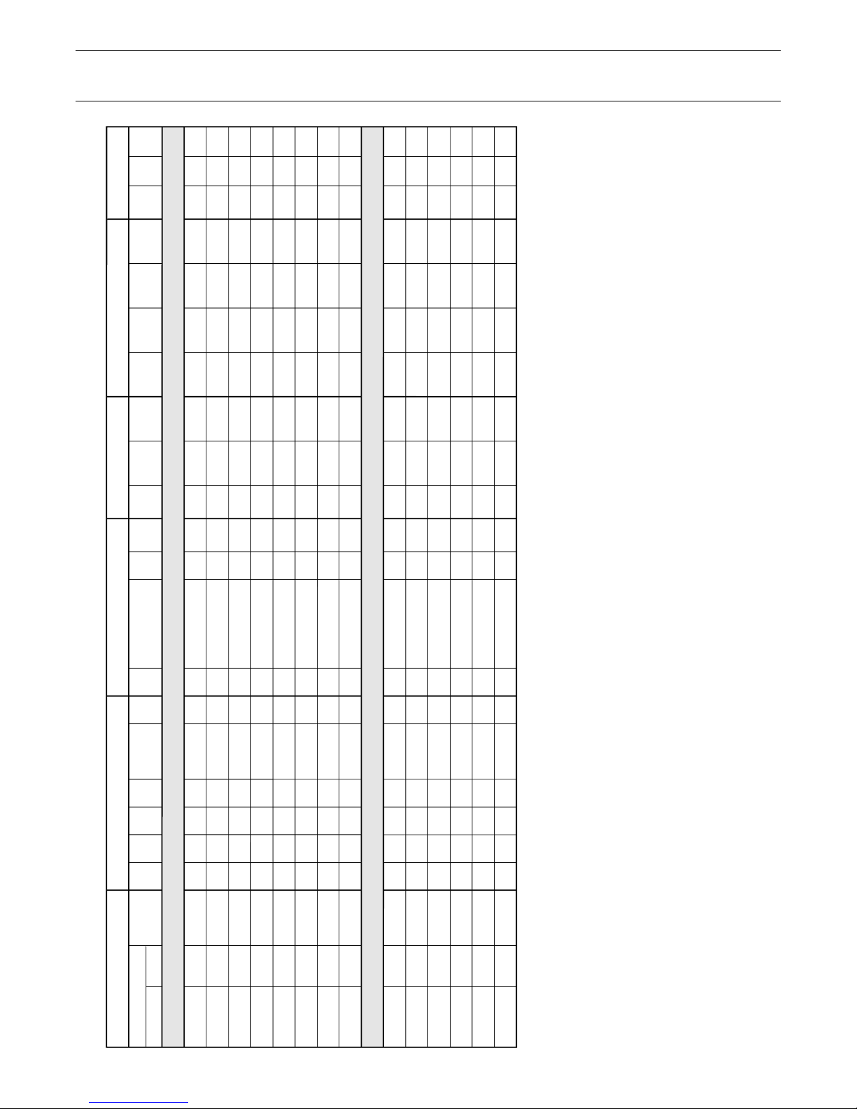
White-Rodgers Integrated Furnace Control Timing
90, 120, 150, 180
90, 120, 150, 180
90, 120, 150, 180
90, 120, 150, 180
60, 100, 140, 180
60, 100, 140, 180
100
100
90, 120, 150, 180
60, 100, 140, 180
90, 120, 150, 180
90, 120, 150, 180
60, 100, 140, 180
60, 100, 140, 180
IFC Timings
50A50-405
50A50-406
50A50-471
50A50-472
50A50-473
50A50-474
50A50-5712
50A55-5710
50A51-405
50A51-495
50A51-505
50A51-506
50A51-507
50A61-625
1 Stage IFC’s
2 Stage IFC’s
E93 – E6
E93 – E6
E90 – E2
E90 – E2
E3
E3
E1 – E2
E91
E93 – E3
E3
E90
E90 & 91
E90
E94
CNT1309
CNT1616
CNT1848
CNT1849
CNT2182
CNT2183
CNT2181
CNT2789
CNT1308
CNT2184
CNT1523
CNT1819
CNT2223
CNT2536
0
0
0
0
0
0
0
0
0
0
0
0
0
0
60
60
60
60
60
60
60
60
120
60
30
30
60
60
5
5
5
5
5
5
5
5
5
5
5
5
5
5
3
3
1
1
1
1
1
1
3
1
3
3
1
1
6
6
4
4
4
4
4
4
6
4
6
6
4
4
NA
8
30
30
30
30
30
30
NA
NA
0
30
30
30
45
45
45
45
45
45
45
45
45
45
45
45
45
45
0
0
0
0
2
2
2
0
0
2
0
0
0
0
0/80
0/80
0/80
0/80
0/80
0/80
0/80
0/80
0/80
0/80
7
7
7
7
2
2
2
2
2
2
2
2
2
2
2
2
2
2
4
4
4
4
10
10
10
10
4
10
4
4
10
10
120
120
120
120
60
60
60
60
120
60
120
120
60
60
17
17
17
17
17
17
17
17
17
17
17
17
17
20
27
27
1
1
1
1
1
1
27
1
27
27
1
9
17
17
11
11
11
11
11
11
17
11
17
17
11
11
27
27
21
21
21
21
21
21
27
21
27
27
21
21
5
5
5
6
5
5
5
5
5
5
5
X
X
X
X
X
X
X
X
X
X
X
Part I.D. Safety Times (Seconds)
White-Rodgers
Model Revs.
Part
Number
Circulator Delays (Seconds)
Pre
Purge
Inter
Purge
Post
Purge
IAP
3
Trial for
Ignition
IND
Off
4
Heat
On
Heat Off
(Factory Set)
Auto Reset
Cool
On
Cool
Off
No. of
Retries
No. of
Recycles
Reset
Time (min.)
Ignitor Warm-Up (Seconds)
Accessories
Initial
Warm-Up
Retry
Warm-Up
Minimum
Warm-Up
Maximum
Warm-Up HUM EAC
Twin
Plug
Notes:
The ignitor starts with a 17 second heat-up timing. After 64 successful cycles, the timing will be shortened each cycle by 1 se
cond until 11 seconds is reached.
If a cycle fails to prove flame, the time will increase by 2 seconds to 13 seconds, then to 15 and so on, up to 21 seconds. 11
min. and 21 max. If a lockout or power loss occurs, the count starts over.
50A50-571 IFC uses a jumper that must be cut to obtain Cool Off Delay. Factory shipped with Jumper not cut = No Cool Off Delay.
IAP = Ignition After Proving. (The amount of time that the ignitor remains energized after the Main Burner Flame is sensed).
IND Off = Time that the Inducer is deenergized after a fault (LED 3 Flash) to allow condensate water (if any) in the Housing to
drain.
Humidifier is energized when the Inducer and the Heat Speed are energized. (“ON” after Heat On Delay – “OFF” after Post Purge).
Humidifier is energized with the Inducer Only. (“ON” with call for heat – “OFF” after Post Purge.)
Time delay to OFF is controlled by the ICM-2 motor control board, DIP switches number 5 and 6.
Prior to E-4 – N/A, E4 and later is 30 seconds.
Ignition warm up – 20 seconds, retry 20 seconds. (Varies voltage on ignitor by 2% reduction on successful cycles)
If cycle fails, then retry, 6% increase. If lockout or power loss, the count starts over.
1
2
3
4
5
6
7
8
9
0
7 Flashes –
8 Flashes –
Slow Flash –
Fast Flash –
Continuous On –
Gas Valve Circuit Error.
Low Flame Sense Signal.
Normal, No Call For Heat Present.
Normal, Call For Heat Present.
Internal Control Failure.
Diagnostic Indicator Flash Codes:
2 Flashes – System Lockout (Retries or Recycles Exceeded).
3 Flashes – Pressure Switch Stuck Open or Closed.
4 Flashes – Open High Temperature Limit Switch.
5 Flashes – Flame Sensed Without Gas Valve.
6 Flashes – 115 Volt AC Power Reversed.
10

White-Rodgers
50A50/50A51 Fault Diagnostics
System Lockout (Loss Of Flame)
When the Control fails to detect a flame current
signal during the trial for ignition period,1 the gas
valve and ignitor will be de-energized and the retry
sequence initiated. During the retry sequence, the
induced draft motor will be energized for an interpurge period.1 The ignition sequence will be restarted
with an additional period1 of ignitor warm-up time
following the interpurge period. The Control will
retry the ignition sequence 2 consecutive times
(3 total) before system lockout.
IMPORTANT
IGNITION CONTROL IS POLARITY SENSITIVE.
HOT LEG OF 120 VOLT POWER SUPPLY
MUST BE CONNECTED TO THE BLACK LINE
POWER LEAD AS INDICATED ON WIRING
DIAGRAM OR IGNITION LOCKOUT WILL OCCUR.
The initial ignition sequence will be recycled, or
repeated, if the flame is sensed and then lost after
10 seconds. The Control retry counter will be reset
if the flame is sustained for longer than 10 seconds
during an ignition recycle attempt. The system will
lockout if the flame is not sustained after the 4th or 10th1
ignition recycle attempt.
A momentary loss of gas supply, flame blowout, or a
shorted or open flame sensor will be sensed
within 0.7 seconds during a normal heating cycle.
The Control will then de-energize the gas valve and
recycle the ignition sequence. As long as the call
for heat still exists, a normal heating operation
will resume if the gas supply returns or the fault
condition is corrected before the 4th or 10th1 ignition
recycle. Otherwise, the Control will go into system lockout.
When a system lockout occurs, the Control de-energizes
the gas valve, energizes the induced draft motor (low
speed on 50A51 Controls) and energizes the indoor blower
on heat speed. The diagnostic LED will begin flashing 2
times to indicate a system lockout due to loss of flame.
If a momentary (50 milliseconds, or longer) loss
of system power occurs during a normal heating
cycle, the gas valve will be de-energized. When the
power is restored, the gas valve will remain de-energized
and the ignition sequence restarted as long as the call
for heat still exists.
When the Control has gone into system lockout
due to loss of flame, the Control must reset before
the system will restart the heating operation. The
Control may be manually reset by setting the
thermostat system switch to OFF and then ON
again within 1 to 21 seconds or by interrupting
system power to the Control for longer than 1 second.
The 50A50 and 50A51 Series Controls automatically
reset a system lockout condition after one or two
hours.1
Pressure Switch Problem
Single-Stage Systems
When a call for heat is received and the pressure
switch contacts are sensed closed before the induced
draft motor is energized, the Control will delay energizing
the induced draft motor, stop the ignition sequence
and begin flashing the diagnostic LED 3 times to indicate
a pressure switch problem. When the pressure switch
contacts open, a normal ignition sequence will begin after
the contacts close again and the 3 flash fault will return
to steady fast flash to indicate a normal call for heat.
When a call for heat is received and the pressure
switch contacts are sensed open after the induced
draft motor is energized, the Control will not allow the
gas valve to open. The ignition sequence will be
stopped and the diagnostic LED begins flashing
3 times to indicate a pressure switch problem. If this
occurs, the problem may be induced draft motor
failure or excessive pressure against the blower outlet
and not allowing the pressure switch contacts to
close. When the pressure switch contacts close, a normal
ignition sequence will begin and the 3 flash fault will
return to a steady fast flash to indicate a normal call
for heat.
If the control senses the pressure switch contacts are
open during a normal heating cycle, the gas valve will
be de-energized to remove the flame and the system
shutdown sequence initiated, induced draft motor will
continue to run. This problem may also be due to
induced draft motor failure or high wind. The Control
will begin flashing the diagnostic LED 3 times to
indicate a pressure switch problem. When the
pressure switch contacts close, a normal ignition
sequence will begin and the 3 flash fault will return to
a steady fast flash to indicate a normal call for heat.
1 See Integrated Furnace Control Label or Timing Chart.
11

White-Rodgers
50A50/50A51 Fault Diagnostics
50A50-405/406 Prior To Revision E4
If the condensate drain is blocked on condensing
(90%) furnace models, either by debris, improper
draining, or by freezing condensate, the pressure
switch contacts will open. When the Control senses
the pressure switch contacts are open, the gas valve
will be de-energized to remove the flame and the
system shutdown sequence initiated. The Control will
begin flashing the diagnostic LED 3 times to indicate
a pressure switch problem. The system will remain
shutdown until the condensate drain has been cleared
and the condensate flows freely. When the pressure
switch contacts close, a normal ignition sequence will
begin and the 3 flash fault will return to a steady fast
flash to indicate a normal call for heat.
During a normal heating cycle, if the 50A50-405/406
Rev. E4-E6/471/472/473/474/571 Control senses the
pressure switch contacts are closed and then open the
gas valve will be de-energized to remove the flame, if
the pressure switch does not reclose in 60 seconds the
induced draft motor will be de-energized for 30 seconds.
After the 30 second delay, a normal ignition sequence
will begin. On condensing (90%) models, the delay
allows any condensate, that may be blocking the
pressure switch sensing tube, time to drain. On 80%
models, the delay provides another attempt for the
induced draft motor to reach maximum speed and
close the pressure switch contacts.
Pressure Switch Problem
50A51-405 Two Stage and 50A51-505 Two Stage
Variable-Speed Systems
On systems using 50A51-405 two-stage and 50A51-505
two-stage variable-speed Controls, the first stage
pressure switch fault diagnostic operation is the same
as the 50A50-405/-406 Controls. (Prior to Revision E4.)
During a normal 1st stage heating cycle, when the
thermostat calls for 2nd stage heat, there will be a
30 second delay between 1st and 2nd stage heat. If
the thermostat calls for 1st and 2nd stage heat at the
same time, there will be a 10 minute delay between
1st and 2nd stage heat.
If the 1st stage pressure switch closes and then opens
during the ignitor warm-up period, the Control will
begin flashing the diagnostic LED 3 times to indicate
a pressure switch problem and wait 10 seconds for
the pressure switch contacts to close. If the 1st stage
pressure switch contacts close, a normal ignition
sequence will resume and the 3 flash fault will return
to a steady fast flash to indicate a normal call for heat.
If the 1st stage pressure switch contacts do not close in
10 seconds, the induced draft motor is energized to high
speed in an attempt to close the contacts. When the
contacts close, a normal ignition sequence will
resume and the induced draft motor will remain
energized on high speed until the flame is sensed for
a minimum of 10 seconds. The induced draft motor
will then be energized to low speed and the 3 flash
fault will return to steady fast flash to indicate a normal
call for heat. If the 1st stage pressure switch contacts
do not remain closed and the ignition sequence has
been recycled for the 4th time, the Control will go into
system lockout and begin flashing the diagnostic
LED 2 times to indicate a system lockout due to loss
of flame.
During a 2nd stage call for heat, if the 2nd stage
pressure switch contacts do not close within the
30 second delay between stages, the Control will
de-energize the gas valve to remove the flame and
begin flashing the diagnostic LED 3 times to indicate
a pressure switch problem. After the Control senses
the loss of flame, a 3 minute error timer will be
started and the shutdown sequence initiated as if
the call for heat were removed. The induced draft
motor will remain energized on high speed for a
5 second postpurge and the (selected) indoor blower
“off” delay timer will begin.
After the 3 minute error time delay, the Control will
restart the heating cycle if the thermostat is still
calling for 1st and 2nd stage heat. If the 2nd stage
pressure switch contacts still have not closed after the
10 minute delay between stages, the Control will
repeat the above shutdown sequence as long as the
thermostat calls for 2nd stage heat.
During the 1st stage ignition sequence, the induced
draft motor will always be energized to high speed. When
the Control senses the 1st stage pressure switch closed,
the induced draft motor is energized to low speed.
1 See Integrated Furnace Control Label or Timing Chart.
12
White-Rodgers
50A50/50A51 Fault Diagnostics
Pressure Switch Problem
50A51-495/-506/-507 Two Stage Variable-Speed Systems
The induced draft motor will always be energized to
high speed. The induced draft motor will be energized
to low speed when the Control senses the 1st stage
pressure switch contacts have closed.
If the 1st stage pressure switch contacts open during
a normal 1st stage heating cycle, the gas valve will
be de-energized to remove the flame and the induced
draft motor will be energized to high speed for
10 minutes. If the 1st stage pressure switch contacts
close during the 10 minute high speed purge, the
Control will restart the ignition sequence. If the
1st stage pressure switch contacts remain closed after
10 minutes, the induced draft motor will be energized
to low speed and a normal heating operation will
continue. If the pressure switch contacts do not close
after 10 minutes, the induced draft motor will be
energized again to high speed for 10 minutes and the
diagnostic LED will begin flashing 3 times to indicate
a pressure switch problem. Recycling the induced
draft motor will continue as long as a 1st stage call
for heat exists and the Control will not go into lockout.
The 2nd stage pressure switch fault diagnostic
operation is the same as 50A51-405/-505 Controls.
Thermal Protection Devices
At any time during a call for heat, if the Control senses
the high temperature limit (and/or aux. limit) or flame
roll out switch(es) are open, the gas valve is de-energized,
the induced draft motor is energized (low speed on
50A51 Controls), and the indoor blower is energized
to run on heat speed.
On models utilizing fusible link devices, the fusible
link is a single use device and must be replaced
if it has opened. However, if the temperature
the fusible link senses is approaching the trip
temperature but does not exceed it, the contacts may
open and close intermittently. The Control will initiate
another ignition sequence upon the closure of the
intermittent fusible link.
Flame Sensed With Gas Valve Off
At any time the Control senses a flame current signal
without a call for heat or when the gas valve is
de-energized, the induced draft motor is energized
(low speed on 50A51 Controls), and the indoor blower
is energized to run on heat speed.1 The Control will
go into system lockout and will not reset until this
fault is corrected. The diagnostic LED will begin
flashing 5 times to indicate the flame sensed with the
gas valve de-energized.
1 See Integrated Furnace Control Label or Timing Chart.
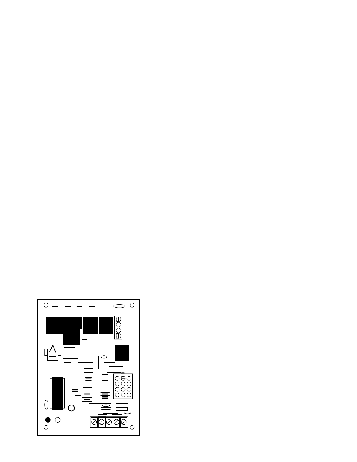
White-Rodgers
PARK LINE-HPARKCOOL-H
E17
E28 E27 E13
HEAT-H XFMR-H
E16 E18 E14
C4
CNT2789
K1
E4
YWR G C
1
1
2
3
4
DS2
ONOFF
DS1
50A55-571/-474 Self Diagnostic Features
Slow Flash – Normal, No Call For Heat Present.
LINE-N
E4
K5K3K2
XFMR-N
CIR-N
E7
E8
E9
E10
E11
Diagnostic Indicator Flash Codes:
2 Flashes – System Lockout (Retries or Recycles Exceeded).
3 Flashes – Pressure Switch Stuck Open or Closed.
K6
E1
4 Flashes – Open High Temperature Limit Switch.
5 Flashes – Flame Sensed Without Gas Valve.
6 Flashes – 115 Volt AC Power Reversed.
7 Flashes – Gas Valve Circuit Error.
FUSE
1
8 Flashes – Low Flame Sense Signal.
See Pages 14 and 15 for Sequence of Operation and
Wire Schematic.
1 Fuse only on 474 Model and Dip Switches replace jumpers.
Fast Flash – Normal, Call For Heat Present.
Continuous On – Internal Control Failure.
13

Single Stage 50A50 and 50A55 Sequence of Operation
White-Rodgers Integrated Furnace
Controls 50A50-405/-406/-471/-472/
-473/-474/-571 and 50A55-571/-474
Models
When the disconnect 1 is in the “ON” position, power
is applied through the blower door interlock switch 6
to the control line voltage input terminal 8 and out of
the control to the primary side of the control transformer
“XFMR” 9. The low voltage side of the transformer
supplies 24 volts to the control through terminals
“TH” o and “TR” i. Control terminal “R” ; supplies 24
volts to the “R” terminal of the room thermostat.
Once power is applied, the control flashes the LED
“ON” for 1 second and performs a self check routine.
Following the normal system check, the control
flashes the LED light once per second continuously
(slow flash) while in stand-by.
On a call for heat, 24 volts is applied from the thermostat
terminal “W” to the “W” terminal ; on the control. The
control checks and confirms normally closed contacts at
the temperature cut out “TCO” f, the auxillary limit
(downflow and some upflow/horizontal models), the
flame roll-out fuse link (two fuse links are used on
downflow and upflow/horizontal models) f and j
and normally open contacts of the safety pressure
switch “PS” f. With all safety and control switches
in their proper position, the control will energize the
induced draft motor y and flash the LED light two times
per second continuously (fast flash) during a call for heat.
When the safety pressure switch “PS” f closes, the
control begins the ignition sequence. The hot surface
ignitor y is energized for several seconds (see note)
allowing the thermal element to heat up. The control
then switches on 24 volts to the gas valve “MV” termi-
nals #1 a. The redundant and main solenoids are
energized allowing gas flow and main burner ignition.
When flame current is detected by the control through
its terminal “FP” k, the 45 second indoor blower motor
delay on timing begins. Flame failure response time
is set for 2 seconds. After flame has been established
for ten seconds, the flame failure response time is
reset for 0.7 seconds. If flame current is not sensed by the
control k within the trial for ignition period (see note),
the redundant and main gas valve solenoids a are
de-energized. The control will begin a interpurge
cycle and adds additional seconds to the hot surface
ignitor warm-up timing (see note). The control
energizes the gas valve a for the second attempt to
establish main burner ignition. If flame current is not
sensed by the control on the 2nd retry within the trial
for ignition period (see note), the control will repeat the
previous cycle one additional time before locking out.
At the end of the indoor blower delay on time, line voltage
is applied at the controls terminal “HEAT” 5 energizing
the indoor blower motor at heating fan speed, supplying
warm air to the space.
When the thermostat is satisfied, the gas valve’s redundant
and main solenoids a are de-energized, extinguishing
main burner flame. Once the control senses loss of
flame current (0.7 sec.) k, the induced draft motor t is
de-energized after a five second post purge cycle. The
indoor blower motor delay off timing begins. At the
completion of the fan delay off timing, the indoor
blower motor 5 is de-energized and the cycle
is complete.
Note: See Timing Chart for details or Integrated Furnace
Control Label.
14
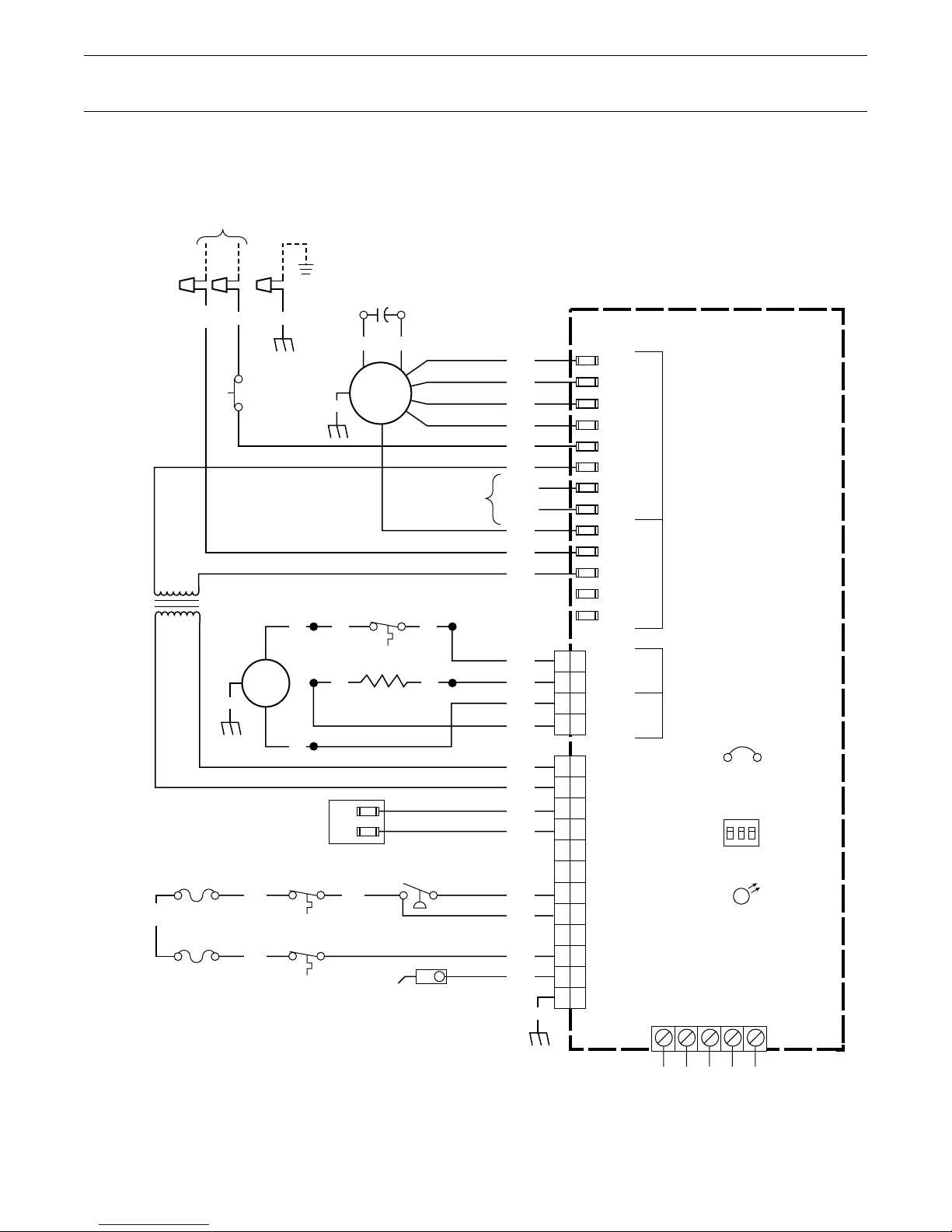
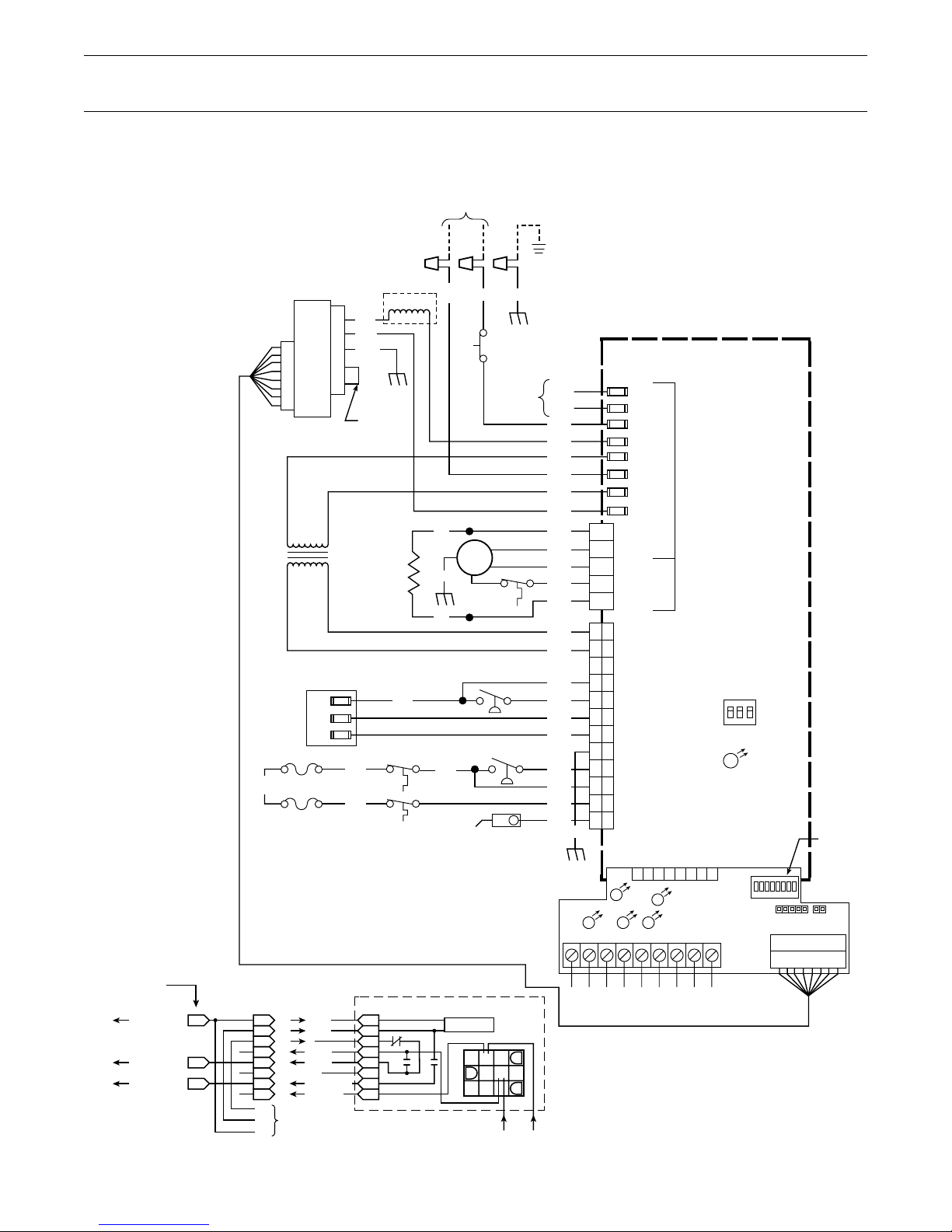
Wiring Schematic
Single Stage (White-Rodger’s 50A50 and 50A55 Series Integrated Furnace Controls)
120 VOLT, 60 HZ., 1 PH.
POWER SUPPLY
1
PER LOCAL CODES
2
3
4
5
6
7
8
9
0
q
w
e
r
t
y
u
i
o
p
a
s
d
f
g
h
j
k
l
;
z
N H
BK
WH/1
DOOR
SWITCH
120V
TNS
24V
IND.
MTR.
GR
GND
GAS VALVE
FUSE LINK4
YL/4
FUSE LINK
2 3 4
1 USED ON 90% FURNACE MODELS ONLY.
2 DIRECT VENT MODELS HAVE ONE MANUAL
RESET FLAME ROLL OUT SWITCH INSTEAD
OF TWO, SINGLE-USE FUSIBLE LINKS.
3 USED ON DOWNFLOW/HORIZONTAL AND
UPFLOW/HORIZONTAL MODELS. TCO-B IS
REVERSE FLOW SWITCH.
4 MAY BE A FUSE LINK OR BIMETAL SWITCH.
YL/2
YL/3
GND
GR
GND
GND
BK
WH WH
WH
TCO
TCO-B
3
GR
BK BK
2
1, 3
YL/1
CF
BR
I.D.
BLOWER
MTR.
1
TCO-B
IGNITOR
C
M
PRESSURE
BR
SWITCH
FLAME
SENSOR
OPTIONAL
BK
“A”
“B”
“C”
BK/1
BK/4
BK/3
BK/2
WH
WH/1
WH/4
BK/6
BK/5
WH/6
WH/5
RD
BL/1
RD/1
OR
YL/5
WH
GND
INTEGRATED FURNACE CONTROL
COOL
HEAT
PARK
PARK
LINE
XFMR
EAC
HUM
CIR N
LINE N
XFMR N
EAC N
HUM N
1
IND
2
IGN
3
IND N
4
IGN N
6
BL
YL
GR
TR
3
TH
9
MV
12
MV
4
5
10
PS
7
HLI
11
1
HLO
2
FP
8
GND
50A50-ALL
HOT 120VAC
NEUTRAL 120VAC
HOT
120VAC
NEUTRAL
JUMPER
50A50-571
DIP
SWITCH
ON
OFF
123
DIAGNOSTIC
LED
YWGRC
TO THERMOSTAT
Note: See Integrated Furnace Control on Timing Chart for Control Details.
15

Two Stage 50A51 Sequence of Operation
White-Rodgers Integrated Furnace
Control 50A51-405/-495 Models
When the service disconnect 1 is in the “ON” position,
power is applied through the blower door interlock
switch 6 to the controls line voltage input terminals 8
and out of the control to the primary side of the
control transformer “XFMR” u. The secondary side
of the control transformer supplies 24 volts to the
control through terminal “TH” and “TR” po. Control
terminal “R” ; supplies 24 volts to the “R” terminal
of the room thermostat.
Once power is applied, the control flashes the LED
light “ON” for one second and performs a self check
routine. Following the normal system check, the
control flashes the LED one time per second (slow flash)
continuously while in stand-by.
On a call for heat, 24 volts is applied from the room
thermostats “W1” terminal to the “W1” terminal z
on the control. The control checks and confirms
normally closed contacts at the temperature cut out
“TCO” j, auxillary limit (downflow and some
upflow/horizontal models), the flame roll-out fuse link
(two fuse links are used on downflow and upflow/
horizontal models) l and normally open contacts at
the safety pressure switch #1 j. With all safety and
control switches in their proper position, the control
will energize the induced draft motor on high speed w
and flashes the LED two times per second continuously
(fast flash) during a call for heat.
When safety pressure switch “#1” j closes, the
control switches the induced draft motor to low speed w
and begins the ignition sequence. The hot surface
|ignitor w is energized for several seconds (see note)
allowing the thermal element to heat up. The control
then switches 24 volts to its “MVL” and “MV COM” g
terminals to terminals #1 g and #2 f on the gas
valve. The redundant and main solenoids are energized
allowing gas flow and main burner ignition. When
flame current is sensed by the control through its
“FP” ; terminal, the 45 second indoor blower motor
time delay “ON” begins. Flame failure response time
is set for 2 seconds. After flame has been established
for 10 seconds, the flame failure response time is
reset for 0.7 seconds. If flamed current is not sensed by
the control within the trial for ignition period (see note),
the main valve low and redundant gas valve
solenoids g, a are de-energized. The control will
begin a interpurge cycle and adds additional seconds
to the hot surface ignitor warm-up timing (see note).
The control energizes the gas valve for the second
attempt to establish main burner ignition. If again
flame current is not sensed by the control within the
trial for ignition period (see note), the control will repeat
the previous cycle before locking out. At the end of
the indoor blower motor delay “ON” timing, line
voltage is applied at control terminal “HEAT LO” 6
energizing the indoor blower motor at low heat fan
speed, supplying warm air to the space.
If the temperature in the space continues to fall, the
thermostat second stage contacts “W2” close.
24 volts is switched from thermostat terminal “W2” to
the “W2” terminal z on the control. A 30 second,
2nd stage recognition time delay begins. At the end of
the 30 second delay, the induced draft motor is
switched to high speed w causing pressure switch #2 d
to close. When pressure switch #2 closes, 24 volts is
switched from control terminal “MVH” d to the gas
valve terminal #3 d energizing the second stage
solenoid allowing increased gas flow to the burners.
At the same time, the indoor blower motor is
switched to high heat fan speed 7.
When second stage thermostat contacts “W2” satisfy,
the induced draft motor is switched back to low speed w
causing pressure switch #2 d to open breaking the
circuit to the second stage gas valve solenoid d. Gas
flow is reduced to the burners. The indoor blower
motor will switch back to low heat fan speed after a
30 second delay 6.
When first stage thermostat contacts “W1” satisfy,
the main valve low and the redundant gas valve
solenoids g are de-energized extinguishing main
burner flame. Once the control senses the loss of
flame current (0.7 sec.) ;, the induced draft motor w
is de-energized after a five second post-purge cycle.
The indoor blower motor “OFF” timing begins. At the
end of the indoor blower motor “OFF” timing, the
indoor blower motor is de-energized and the cycle
is complete.
Note: See Timing Chart for details or Integrated Furnace
Control Label.
16
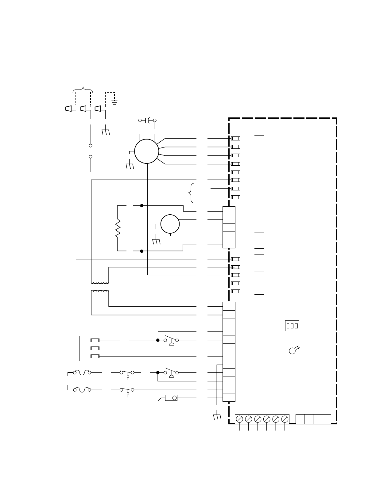
Wiring Schematic
Two Stage Heat (White-Rodgers 50A51 Series Integrated Furnace Control)
120 VOLT, 60 HZ., 1 PH.
POWER SUPPLY
1
PER LOCAL CODES
2
3
4
5
6
7
8
9
0
q
w
e
r
t
y
u
i
o
p
a
s
d
f
g
h
j
k
l
;
z
N H
WH/1
TNS
GAS VALVE
FUSE LINK 2
YL/4
FUSE LINK
1 2
3
2
1
BK
DOOR
SWITCH
IGNITOR
120V
24V
HI
B/C
LO
YL/2
YL/3
GR
GND
GND
1 TCO-B
GND
BR/1
TCO
WH
WH
GR
CF
BR
I.D.
BLOWER
MTR.
YL/1
BR
OPTIONAL
IND.
MTR.
GR
GND
PRESSURE SWITCH
2ND STAGE
PRESSURE SWITCH
1ST STAGE
FLAME
SENSOR
BK
“A”
“B”
“C”
BK/1
BK/4
BK/2
BK/3
BK/5
BK/6
RD/6
WH/6
WH/5
WH/1
WH/4
WH
BL
RD
BR
OR/1
BL/1
RD/1
OR
YL
YL/5
WH
GND
INTEGRATED FURNACE CONTROL
COOL
PARK
HEAT LO
HEAT HI
LINE
XFMR
EAC
HUM
1
IGN
2
IND HI
3
IND LO
4
IND N
5
IGN N
LINE N
XFMR N
CIR N
EAC N
HUM N
9
TR
5
TH
10
GND
2
PS2
1
MVH
8
MVCOM
7
MVL
4
GND
12
PSI
6
HLI
11
HLO
3
FP
GR
W1 W2 Y
50A51-405
HOT 120VAC
NEUTRAL
120VAC
HOT
120VAC
NEUTRAL
GB
R
DIP
SWITCH
123
DIAGNOSTIC
LED
ON
OFF
COMCLHI
LO
1 USED ON DOWNFLOW/HORIZONTAL AND
UPFLOW/HORIZONTAL MODELS. TCO-B IS
REVERSE FLOW SWITCH.
2 MAY BE A FUSE LINK OR BIMETAL SWITCH.
Note: See Integrated Furnace Control on Timing Chart for Control Details.
17
TO THERMOSTAT
FURNACE
TWINNING
CONNECTOR

Two Stage Variable Speed Sequence of Operation
White-Rodgers Integrated Furnace
Controls 50A51-505/-506/-507 and
50A61-605 Models
When the service disconnect 1 is in the “ON” position,
power is applied through the blower door interlock
switch 3 to the controls line voltage input terminals 6
and out of the control to the primary side of the
control transformer 9, and from the “ CIRC” 7
terminal to the ECM
side of the control transformer supplies 24 volts to the
control through terminal “TH” and “TR” w, e. Control
terminal “R” g supplies 24 volts to the “R” terminal
of the room thermostat.
Once power is applied, the control flashes the LED
light “ ON” for one second and performs a self
check routine. Following the normal system check, t
he control flashes the LED one time per second (slow flash)
continuously while in stand-by.
On a call for heat, 24 volts is applied from the room
thermostats “W1” terminal to the “W1” terminal g
on the control. The control checks and confirms
normally closed contacts at the temperature cut
out “TCO” a, auxillary limit (downflow and some
upflow/horizontal models), the flame roll-out fuse link
(two fuse links are used on downflow and some
upflow/horizontal models) a and normally open
contacts at the safety pressure switch #1 p. With all
safety and control switches in their proper position,
the control will energize the induced draft motor on
high speed 9 and flashes the LED two times per
second continuously (fast flash) during a call for heat.
When safety pressure switch “#1” p closes, the
control switches the induced draft motor to low
speed 0 and begins the ignition sequence. The hot
surface ignitor 9 is energized for several seconds
allowing the thermal element to heat up. The control
then switches 24 volts to its “MVL” i and “MV
COM” u terminals to terminals #1 i and #2 u on
the gas valve. The redundant and main solenoids are
energized allowing gas flow and main burner ignition.
When flame current is sensed by the control through
its “FP” f terminal, the 45 second indoor blower
motor time delay “ON” begins. Flame failure response
time is set for 2 seconds. After flame has been
established for 10 seconds, the flame failure response
time is reset for 0.7 seconds. If flamed current is not
sensed by the control f within the trial for ignition
period, the main valve low and redundant gas valve
solenoids i are de-energized. The control will begin
a 30 second interpurge cycle and adds additional
TM
Fan Motor 3. The secondary
seconds (see note) to the hot surface ignitor warm-up
timing. The control energizes the gas valve for the
second attempt to establish main burner ignition.
If again flame current is not sensed by the control
within the trial for ignition period (see note), the
control will repeat the previous cycle before locking
out. At the end of the indoor blower motor delay
“ON” timing, the microprocessor will close the
normally open K3 relay contacts j completing a
24 volt signal circuit to pin #15 of the ECM
TM
motor,
signaling it to turn on and run at the low heat blower
speed, supplying warm air to the space. 24 volts
W1 g terminal from the thermostat is also applied
to the ECM
the ECM
TM
motor harness pin #12h, which signals
TM
motor to run at the low heat speed setting.
If the temperature in the space continues to fall, the
thermostat second stage contacts “W2” close.
24 volts is switched from thermostat terminal “W2” to
the “W2” terminal g on the control. A 30 second,
2nd stage recognition time delay begins. At the end
of the 30 second delay, the induced draft motor is
switched to high speed 9 causing pressure switch
#2 o to close. When pressure switch #2 closes,
24 volts is switched from control terminal “MVH” o to
the gas valve terminal #3 o energizing the second
stage solenoid allowing increased gas flow to the
burners. At the same time, the microprocessor
closes the normally open K1 relay contacts j
completing a 24 volt signal circuit to pin #13 k of the
TM
ECM
2 motor signaling the indoor blower motor to
run at the high heat blower speed.
When second stage thermostat contacts “W2” satisfy,
the induced draft motor is switched back to low
speed 0 causing pressure switch #2 y to open
breaking the circuit to the second stage gas
valve solenoid y. Gas flow is reduced to the burners.
The indoor ECM
TM
blower motor 4 will be switched
back to the low heat fan speed after a 30 second delay.
When first stage thermostat contacts “W1” satisfy,
the main valve low and the redundant gas valve
solenoids i are de-energized extinguishing main
burner flame. Once the control senses the loss of
flame current (0.7 sec.)f, the induced draft motor 9
is de-energized after a five second post-purge cycle.
The indoor blower motor “OFF” timing begins. At the
end of the indoor blower motor “OFF” timing, the indoor
blower motor is de-energized and the cycle is complete.
Note: See Timing Chart for details or Integrated Furnace
Control Label.
18
Wiring Schematic
Two Stage Variable Speed
Furnace Controls)
1
2
3
4
5
6
7
8
9
0
q
w
e
r
t
y
u
i
o
p
a
s
f
g
TNS
FUSE LINK5
YL/4
FUSE LINK
ECMTM2
BLOWER
MOTOR
120V
24V
GAS VALVE
3
2
1
2 3 5
(White-Rodgers 50A51 and 50A61 Series Integrated
120 VOLT, 60 HZ., 1 PH.
POWER SUPPLY
PER LOCAL CODES
N H
1
LC
5
BK/8
WH/7
4
3
GR/BK
2
1
JUMPER
YL/BK
GND
WH
WH/1
BK
DOOR
SWITCH
OPTIONAL
IND.
MTR.
GR
GND
WH
PRESSURE SWITCH
2ND STAGE
PRESSURE SWITCH
1ST STAGE
YL/1
TCO-C4
FLAME
SENSOR
YL/2
YL/3
IGNITOR
HI
B/C
LO
BR/1
TCO
2 TCO-B
GND
GR
GND
50A51-505/-506
INTEGRATED FURNACE CONTROL
BK/2
BK/3
BK/1
BK/7
BK/4
WH/1
WH/4
WH/7
BK/5
BK/6
RD/6
WH/6
WH/5
BL
RD
BR
OR/1
BL/1
RD/1
OR
YL
YL/5
WH
GR
GND
1
2
3
4
5
9
5
10
2
1
8
7
4
12
6
11
3
CFM
IGN
IND HI
IND LO
IND N
IGN N
TR
TH
GND
PS2
MVH
MVCOM
MVL
GND
PS1
HLI
HLO
FP
P2
EAC
HUM
LINE
CIRC
XFMR
LINE N
XFMR N
CIR N
W1 IN
W2 IN
G IN
R OUT
1234567
FAN
HOT 120VAC
NEUTRAL
120VAC
DIAGNOSTIC
G OUT
N/C
W2 OUT
B OUT
8
DIP
SWITCH
1
23
LED
ON
OFF
ON
OFF
ECMTM FAN CONTROL
R
BK O Y YLOGW1W2B
P1
LVTB
DIP SWITCH
h
j
k
16 WIRE
HARNESS
W1
CFM
G
FAN
ON/OFF
W2
CFM
INTERFACE CONTROL BOARD
AT INTEGRATED CONTROL
P1
2
P1
15
P1
13
PIN CONNECTIONS
P2
1
P2
2
P2
3
P2
4
P2
5
P2
6
P2
7
P2
8
G
TERMINAL
W2
BOARD
W1
W1 IN
W2 IN
G
R OUT
G OUT
N.C.
W2 CFM OUT
B OUT
INTEGRATED FURNACE CONTROL
TYPICAL CONNECTION
8
K3K2K1
1
COMPUTER
19
TR
TH
R B/C
24 VAC IN
TO THERMOSTAT
16 WIRE HARNESS
1 LINE CHOKE NOT USED ON ALL MODELS.
2 USED ON DOWNFLOW/HORIZONTAL AND UPFLOW/HORIZONTAL
MODELS. TCO-B IS REVERSE FLOW SWITCH.
3 DIRECT VENT MODELS HAVE ONE MANUAL RESET FLAME ROLL
OUT SWITCH INSTEAD OF TWO, SINGLE-USE FUSIBLE LINKS,
OR AUTO-RESET BIMETAL SWITCHES MAY BE USED ON SOME MODELS.
4 USE ON 90% FURNACE MODEL ONLY.
5 MAY BE A FUSE LINK OR A BIMETAL SWITCH.

Integrated Control Quick Reference
Service Tips
To the qualified service man, these controls are
very simple and easy to work on. A list of required
service tools needed to work on any solid state
ignition control today are listed below:
A reliable Volt/OHM Multimeter (preferably a
digital with a microamp scale on it). The Microamp
Meter is used to measure flame current.
A U-Tube Water Manometer (or pressure gauge) to
test inlet and out gas valve pressure.
An Incline Manometer with a 0-2" water column scale
to test pressure switches and ductwork static pressure.
1. When the thermostat fan switch is placed in the
“ON” position, the fan will run at heating fan speed.
Low heat fan on two stage 50A51 series controls.
2. In order to obtain cooling air flow, the thermostat
“Y” terminal must be connected to the “Y” terminal
on the control. If the “Y” is not connected, low
heat speed will be activated during a cooling cycle.
3. If a single stage heat thermostat is used with the
50A51 two stage control, there will be a 10 minute
delay between first and second stage heat if W1 and
W2 are jumpered.
8. If a lockout occurs, the control automatically resets
the trial for ignition sequence every one or two hours
provided a call for heat continues to exist. See Timing
Chart , Reset Time Column, for details.
9. To reset control after lockout:
a. Interrupt line voltage power to the control for
a minimum of 1 second.
b. Turn thermostat system switch off and back on
twice within 30 seconds.
10. Voltage input range:
Line 97-132 VAC 50/60HZ – Nominal 120 volts AC
Control 20-30 VAC 50/60HZ – Nominal 24 volts AC
11. 50A50 controls with date codes prior to 9348
require an isolation relay in the “Y” circuit
when used with Add On Heat Pump Plus One kits,
to prevent cold air complaints during defrost.
The control would not allow a cooling (Y) and
heating (W) output at the same time so the control
would de-energize the “W” circuit and there would
be no supplement heat during defrost cycles.
12. The humidifier accessory lead is energized
whenever there is a heating call and the fan is
operating. See IFC Timing Chart for details, page10.
4. The control requires one microamp DC minimum
flame current in order to maintain a call for heat.
5. The control will add seconds to the igniter
heat-up period on second and third trial for ignition
with interpurge between trials. See Integrated
Furnace Control label or Timing Chart for details.
6. Once flame current has been established by the
control for 10 seconds, the retry counter in the control
is reset to zero.
7. If flame current is interrupted, the control will
break current flow to the gas valve and immediately
begin a recycle for ignition without a purge cycle or
increase in igniter warm-up time. If flame current is
interrupted during 2nd stage operation, the recycle
sequence is initiated and Hi fire or 2nd stage will
resume immediately.
13. The electronic air cleaner accessory lead is
energized whenever there is a 24 volt signal on G or Y
or during a heating call when the indoor fan is
operating.
A detailed troubleshooting chart for each model of
the integrated furnace control is included in this
manual to help the service technician work through
abnormal conditions with these controls.
The troubleshooting section with fault charts for all
White-Rodgers controls are located on pages 48
through 62. See page 48 for procedures and chart
references.
20
 Loading...