

American Standard 2TEE3D49A1000A, 2TEE3D31A1000A, 4TEE3D40A1000A, 4TEE3D31A1000A, 4TEE3D37A1000A Installer's Manual
...
Installer’s Guide
▲
▲
18-GE10D1-5
Convertible Variable Speed – Air Handlers 2 1/2 - 5 Ton
with Integrated Whole House Air Cleaner
2/4TEE3D31A1000A, 2/4TEE3D37A1000A, 2/4TEE3D40A1000A,
2/4TEE3D49A1000A, 2/4TEE3D65A1000A
WARNING:
ALL phases of this installation must comply with NATIONAL, STATE AND LOCAL CODES
IMPORTANT — This Document is customer property and is to remain with this unit. Please return to service information
pack upon completion of work.
A. GENERAL INFORMATION
!
THIS INFORMATION IS FOR USE BY INDIVIDUALS
HAVING ADEQUATE BACKGROUNDS OF ELECTRICAL
AND MECHANICAL EXPERIENCE. ANY ATTEMPT TO
REPAIR A CENTRAL AIR CONDITIONING PRODUCT
MAY RESULT IN PERSONAL INJURY AND/OR PROPERTY DAMAGE. THE MANUFACTURER OR SELLER
CANNOT BE RESPONSIBLE FOR THE INTERPRETATION OF THIS INFORMATION, NOR CAN IT ASSUME
ANY LIABILITY IN CONNECTION WITH ITS USE.
!
To prevent shortening its service life, the air handler
should not be used during the finishing phases of construction. The low return air temperatures can lead to
the formation of condensate. Condensate in the presence of chlorides and fluorides from paint, varnish,
stains, adhesives, cleaning compounds, and cement
creates a corrosive condition which may cause rapid
deterioration of the cabinet and internal components.
HAZARDOUS VOLTAGE - DISCONNECT POWER BEFORE SERVICING
CONTENTS
WARNING
CAUTION
General Information .............................................. 1
Installation Limitations & Recommendations ...................... 1
Two Piece Cabinet Disassembly ........................ 4
Unit Installation ...................................................... 4
Vertical Upflow ....................................................................... 4
Vertical Downflow ................................................................... 5
Horizontal Left ........................................................................ 9
Horizontal Right ................................................................... 10
Duct Connection ................................................... 10
Refrigerant Piping ............................................... 13
Brazing to Evaporator Section ......................... 1 3
Condensate Drain Piping .................................... 13
Electrical - Wiring ................................................. 14
Airflow Adjustment ............................................... 15
Maintenance Check Out Procedure ................ 16
This unit is equipped with an integrated high efficiency
Whole House Air Cleaner. Careful consideration must
be taken in the installation process to avoid personal injury or equipment damage. These instructions do not
cover all variations in systems or provide for every possible contingency. Should further information be desired
or particular problems arise which are not covered sufficiently by this manual, contact your local distributor or
the manufacturer as listed on the air handler nameplate.
These Air Handlers are shipped from the factory in the
upflow or horizontal right configuration and are fully
convertible to downflow or horizontal left. Refer to Section C beginning on page 4 for additional information.
INSPECTION
Check carefully for any shipping damage. This must be
reported to and claims made against the transportation
company immediately. Check to be sure all major components are in the unit. Any missing parts should be reported to your supplier at once, and replaced with authorized parts only.
Cleaning the COLLECTION CELL .................. 1 6
Cleaning the FIELD CHARGER ........................ 17
Hook Up Diagrams ............................................... 18
Outline Drawings ................................................. 20
Checkout Procedures .......................................... 23
INSTALLATION LIMITATIONS & RECOMMENDATIONS
The general location of the air handler is normally selected by the architect, contractor and/or home owner
for the most effective application and satisfaction.
NOTE: Condensation may occur on the surface of the
air handler when installed in an unconditioned location. When units are installed in unconditioned spaces,
verify that all electrical and refrigerant line penetrations
on the air handler are sealed completely.
Installer’s Guide
▲
These air handlers are suitable for installation in a
closet, alcove or utility room with free, non-ducted, air
return, using the area space as a return air plenum.
With ducted supply air, if the minimum clearances to
combustible materials and service access are observed,
the above installations are suitable.
This area may also be used for other purposes, including an electric hot water heater- but in no case shall
a fossil fuel device be installed and/or operated in
the same closet, alcove or utility room.
In addition, these air handlers are suitable for installation in an attic, garage or crawl space with ducted supply and return air.
This equipment has been evaluated in accordance with
the U.S. Department of Housing and Urban Development code. Air handler is Suitable for mobile home/
manufactured housing use. Unit is also approved for
modular homes.
For proper installation the following items must be considered:
1. If adequate power is available and correct according
to nameplate specifications.
2. Prior to unit installation, a heavy gauge steel
plate is attached to the bottom of the unit for
protection during shipping and handling.
Leave this plate in place until the unit is
ready to be connected to ductwork.
3. Insulate all ducts, particularly if unit is located outside of the conditioned space.
4. Pursuant to Florida Building Code 13-610.2.A.2.1,
this unit meets the criteria for a factory sealed
air handler.
5. To ensure maximum efficiency and system performance, the existing supply and return duct system
static pressures must not exceed the total available
static pressure of the air handler. Reference ACCA
Manual D, Manual S and Manual RS along with the
air handler Product Data and Service Facts for additional information.
6. It is recommended that the outline drawing be studied and dimensions properly noted and checked
against selected installation site. By noting in advance which knockouts are to be used, proper clearance allowances can be made for installation and future service.
7. Allow a minimum of 21 inches clearance in front
of the air handler to permit removal of COLLECTION CELL and FIELD CHARGER.
8. Do not install air handler where air cleaner can be
exposed to UV light.
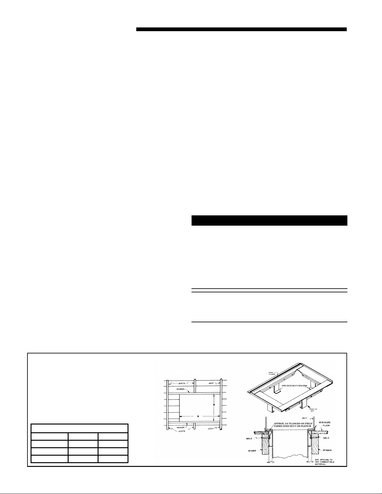
9. When the air handler with supplementary heater is
to be installed in the downflow position on combustible flooring an accessory sub-base (TAYBASE101
for 2/4TEE3D31, TAYBASE100 for 2/4TEE3D37,
TAYBASE102 for 2/4TEE3D40-65) must be used.
See Figure 1.
10. If supplementary heat is to be added, power supply
must be sufficient to carry the load. In addition,
minimum airflow settings, unit and duct clearances
to combustible material must be maintained as
stated on the air handler rating nameplate.
!
CAUTION
For air handlers not equipped with a factory installed
electric heater, a field installed heater is available from
Trane. Only heaters built by Trane are approved for use
in the air handler. These heaters have been designed
and tested in accordance with UL standards to provide
safe and reliable operation. A list of approved heaters
is provided on the air handler rating nameplate. Heaters that are not factory approved could cause damage
and are not covered under equipment warranty.
NOTE: If air handler is used WITHOUT a supplementary electric heater, a sheetmetal plate is required to
cover the open hole in the airflow system. See Figure
3
.
Figure 1
MODEL NO. A B
TAYBASE100 23-3/4 14-13/16
TAYBASE101 21-3/4 14-13/16
TAYBASE102 26-3/4 14-13/16
© 2008 Trane 18-GE10D1-4
AIR HANDLER SUB-BASE
FLOOR OPENING - SIZE
Installer’s Guide
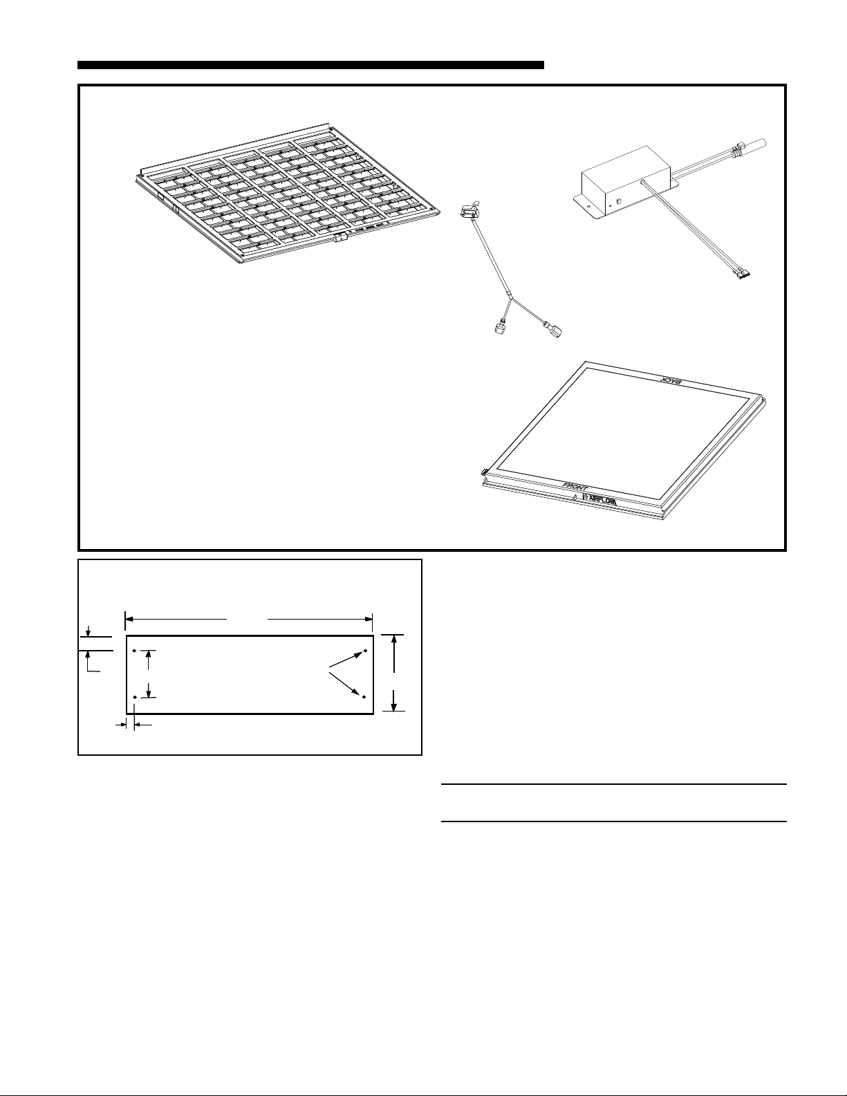
Figure 2
Components of the Integrated Whole House Air Cleaner
1
1) FIELD CHARGER - Charges the contaminants
2) COLLECTION CELL - removes and collects very small
impurities from the air.
3) Power Supply - the solid state power supply converts the
24 Volt AC to the high-voltage, direct current required to
power the FIELD CHARGER and COLLECTION CELL.
4) Safety Switch - cuts off all power to the FIELD CHARGER
and COLLECTION CELL when disengaged.
Check carefully for any shipping damage. This must be
reported to and claims made against the transportation company immediately. Check to be sure all major
components are in the unit. Any missing parts should
be reported to your supplier at once, and replaced with
authorized parts only.
3
4
2
IF AIRHANDLER IS USED
SUPPLEMENTARY HEATER, A PLATE IS REQUIRED TO COVER
THE OPEN HOLE IN THE AIR FLOW SYSTEM
1"
4"
3/8"
WITHOUT
17"
ACCESSORY BAY99X123
Figure 3
A FACTORY FURNISHED
1/4" HOLES (4)
6"
From Dwg. 21B140413
11. If the unit is installed without a return air duct, applicable local codes may limit this air handler to installation only in a single story residence & within
conditioned space.
12. If the outdoor unit is to be installed later, or by others, then installation of the air handler must be
made to allow access for refrigerant lines, or attach
refrigerant lines to air handler when installing.
13. Make sure there are provisions for installing condensate drain lines.
14. If side, front or rear return is required, air handler
must be elevated or placed on a plenum
(TAYPLNM100 or 101). Connecting return duct directly to the side, front or rear of the cabinet is not
approved.
15. Route refrigerant & condensate drain lines away
from air handler so they do not interfere with access panels and COLLECTION CELL removal.
16. When external accessories are used, the additional
height and width requirements must be considered
in the overall space needed.
17. These units are not approved for outdoor installation.
18. These units are approved for draw-through application
only.
19. DO NOT use silicon based sealant. This causes a
coating on the FIELD CHARGER pins that will decrease the efficiency of the air cleaner.
NOTE: No atomizing style humidifier is allowed in the
return plenum with the use of this unit.
20. Flow-through Bypass Humidifiers
Excessive bypass air may cause water blow-off,
which will adversely affect system operation and air
cleaner performance. To verify bypass airflow, follow the Bypass Humidifier Pre-Installation Checkout and Set-Up Procedures available through your
local distributor. Ask for publication number 18CH37D1-1.
18-GE10D1-4 3

Installer’s Guide
▲
Steam and Flow-through Fan Power Ductmounted Humidifiers
Follow the humidifier installation instructions.
These should only be installed on the supply air
side of the system.
Other Duct Mounted Humidifiers are Not recommended for installation with the air
cleaner.
21. Unit installation must include either a return air
duct or grill that prevents accidental access to pins.
For upflow open air intake applications that do not
have a grill or return air duct, installation will require the use of either BAYPLNM120, TASB215,
TASB235, or TASB260 depending on cabinet size.
TASB accessories can be purchaed from:
Miami Tech Inc.
3611 NW 74 Street
Miami, Florida 33147
Phone: 800-339-2290
Fax: 305-693-6152
www.miamitech.com
TASB215 for use with 21.5" cabinets 2/4TEE3D31
TASB235 for use with 23.5" cabinets 2/4TEE3D37
TASB260 for use with 26.0" cabinets 2/4TEE3D40,49,
and 65
22. A PRE-FILTER is not required to be installed with
the air handler containing a Whole House Air
Cleaner. If the use of a PRE-FILTER is desired, it
must be installed at least 6" away from the Whole
House Air Cleaner.
B. TWO PIECE CABINET DISASSEMBLY
(OPTIONAL)
NOTE: For easier installation into tight areas, the 4
and 5 ton air handlers can be disassembled and reas-
sembled after moved to an attic or other space.
Steps for disassembly and reassembly (See Figures 4
and 5)
1. Disconnect wiring.
2. Remove center bracket.
3. Remove blower assembly.
4. Remove coil.
5. Cut foil tape - minimum 3" foil tape.
6. Remove top 8 screws. See Figure 3.
7. Lift upper section.
8. Set air handler in place.
9. Attach screws - insure gaskets are aligned
along flange.
10. Use foil tape to seal - use minimum 3" foil tape.
11. Insert coil.
12. Reinstall blower assembly.
13. Reinstall center bracket.
14. Reconnect wiring.
NOTE: In Downflow, remove coil before blower by
reversing steps 4 and 5.
SCREWS 5-8
LOCATED ON
LEFT SIDE
2
1
3
4
Figure 4 Closeup of Spear Locations
Figure 5
2 Piece Wrapper Spear
C. UNIT INSTALLATION
UPFLOW
!
CAUTION
When unit is installed in non-ducted applications,
BAYPLNM120 must be used.
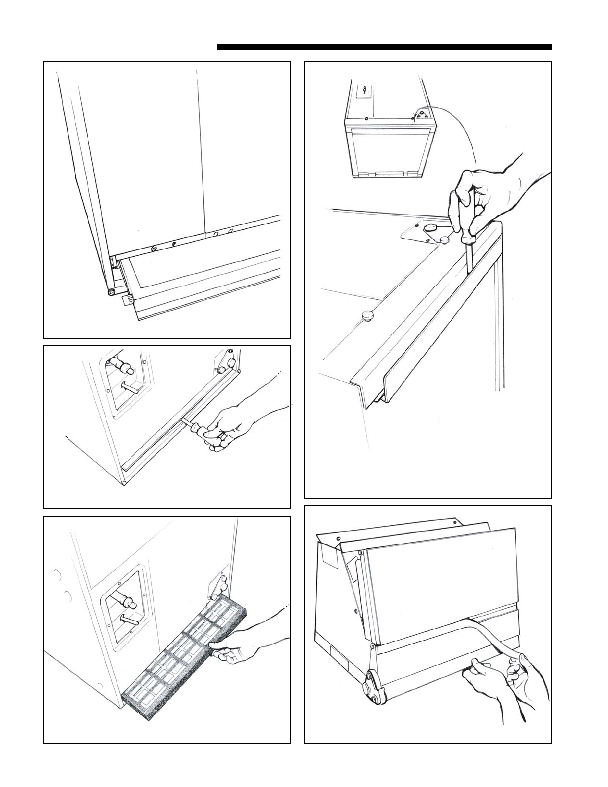
a. Before installing unit, remove thumbscrews to
the filter panel. Carefully remove the COLLECTION CELL by grasping the leading edge of the
frame. See Figure 6. Set aside in a safe place until the unit is set in place and ready to start up.
b. Use a 5/16" nutdriver to remove the screws hold-
ing the FIELD CHARGER retainer and take out
both. Slightly lift the FIELD CHARGER and carefully remove. Set aside in a safe place until the
unit is set in place and ready to start up. See Figures 7 and 8.
c. Position unit to remove the bottom protector
plate by laying the unit on its back. Use a flat
blade screwdriver between the protector plate
and the unit to pry apart. See Figure 9. Gently
pull the plate towards the front of the unit to remove.
4 18-GE10D1-5

Installer’s Guide
▲
▲
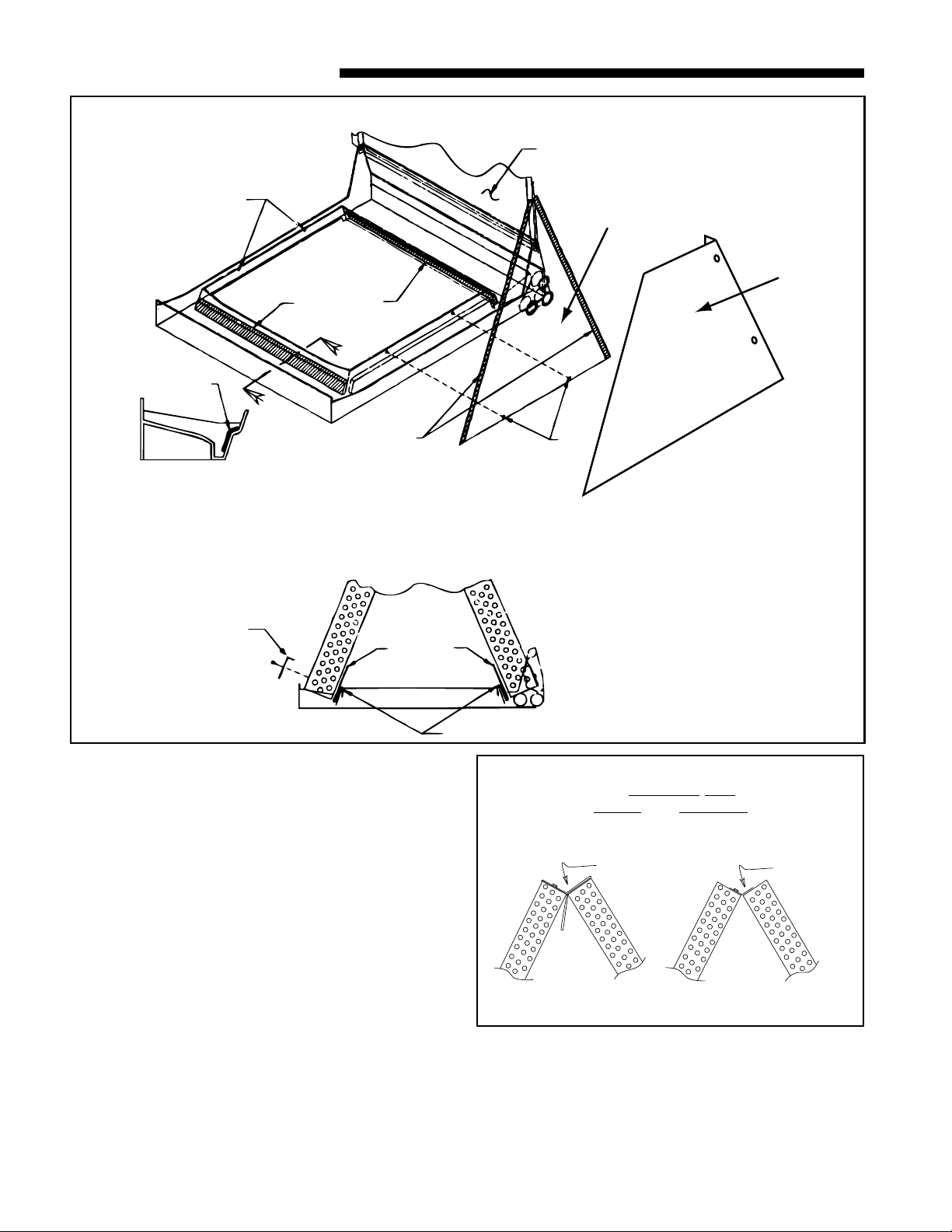
d. For maximum efficiency, the horizontal drip
tray should be removed. See Figures 10, 11 and
12. Tray removal requires that the coil be removed by sliding the coil out on the coil channel
supports. For the TEE3D40-65 units, there is a
coil support tab at the top of the coil connected to
the case that must be removed first. Remove 1
inch insulation strip covering the lip of the drip
tray. The tray is detached by removing the two
screws at the drain pan. Remove the two screws
holding the two brackets at the top of the coil.
Remove drip tray by gently breaking the seal between the drip tray and drain pan.
e. Remove the factory installed baffle assembly
from the apex of the coil by using a 5/16"
nutdriver to remove the screws. Replace this
baffle with the factory supplied narrow coil baffle
using the screws removed previously. See Figure
15. Reinstall coil assembly.
!
CAUTION
When installing the narrow coil baffle, make sure to
align the baffle up with the holes so NOT to puncture
the coil tubing.
f. Position unit on Pedestal or other suitable foun-
dation. If Pedestal is not used, a frame strong
enough to support the total weight must be provided. Provide a minimum height of 14 inches for
proper unrestricted airflow. In open return applications, installation requires a BAYPLNM or
TASB stand.
g. If a return air duct is connected to the air han-
dler, it must be the same dimensions as shown in
the outline drawing on page 20.
h. On units with sheetmetal returns: Return
plenum must be flanged. Sheetmetal screws
must be 1/2" in length or shorter. Self-tapping screws are supplied with unit in accessory pack. See Figure 17.
i. No sheetmetal screws may be used to at-
tach return duct work on the side of the
unit.
j. Pedestal and unit should be isolated from the
foundation using a suitable isolating material.
k. Openings where field wiring enters the
cabinet must be completely sealed. Location
of power entry is shown on the Outline Drawing.
Use 2.5" clear stickers provided to seal all unused
electrical knockouts. See Figure 16.
l. After ductwork connections are made, seal air-
tight and per Local codes.
m. Install FIELD CHARGER as shown in Figure 18
(Upflow). Ionizing pins must face downward (into
the return air stream) and electrical contacts
must be on the left side of the unit.
n. Reinstall FIELD CHARGER retainer bracket.
18-GE10D1-5 5
o. Install COLLECTION CELL as shown in Figure
18 (Upflow) so that electrical contacts and actuator tab are on the left side of the unit.
p. Install filter panel with thumbscrews.
DOWNFLOW
a. Before installing unit, remove thumbscrews to
the filter panel. Carefully remove the COLLECTION CELL by grasping the leading edge of the
frame. See Figure 6. Set aside in a safe place until the unit is set in place and ready to start up.
b. Use a 5/16" nutdriver to remove the screw in the
FIELD CHARGER retainer and take out both.
Slightly lift the FIELD CHARGER and carefully
remove. Set aside in a safe place until the unit is
set in place and ready to start up. See Figures 7
and 8.
c. Position unit to remove the bottom protector
plate by laying the unit on its back. Use a flat
blade screwdriver between the protector plate
and the unit to pry apart. See Figure 9. Gently
pull the plate towards the front of the unit to remove.
d. For maximum efficiency, the horizontal drip
tray should be removed. See Figures 10, 11 and
12. Tray removal requires that the coil be removed by sliding the coil out on the coil channel
supports. For the TEE3D40-65 units, there is a
coil support tab at the top of the coil connected to
the case that must be removed first. Remove 1
inch insulation strip covering the lip of the drip
tray. The tray is detached by removing the two
screws at the drain pan and the two screws holding the two brackets at the top of the coil. Remove drip tray by gently breaking the seal between the drip tray and drain pan.
e. Remove the factory installed baffle assembly
from the apex of the coil by using a 5/16"
nutdriver to remove the screw. Replace this
baffle with the factory supplied narrow coil baffle
using the screws removed previously. See Figure
15.
!
CAUTION
When installing the narrow coil baffle, make sure to
align the baffle up with the holes so NOT to puncture
the coil tubing.
NOTE: Installation of the downflow baffle kit included
with unit is required on downflow applications. See
Figure 14.
f. Remove front shield by removing screws on right
side. Make sure to reinstall front shield after
baffle changes. See Figure 14.
g. Detach the coil from the drain pan by removing 4
screws as shown in Figure 14.
Installer’s Guide
Figure 6 COLLECTION CELL Removal
Figure 9 Protector Plate Removal
Figure 7 FIELD CHARGER Retainer Bracket Removal
Figure 8 FIELD CHARGER Removal
6 18-GE10D1-5
Figure 10 Drip Pan Foam Removal
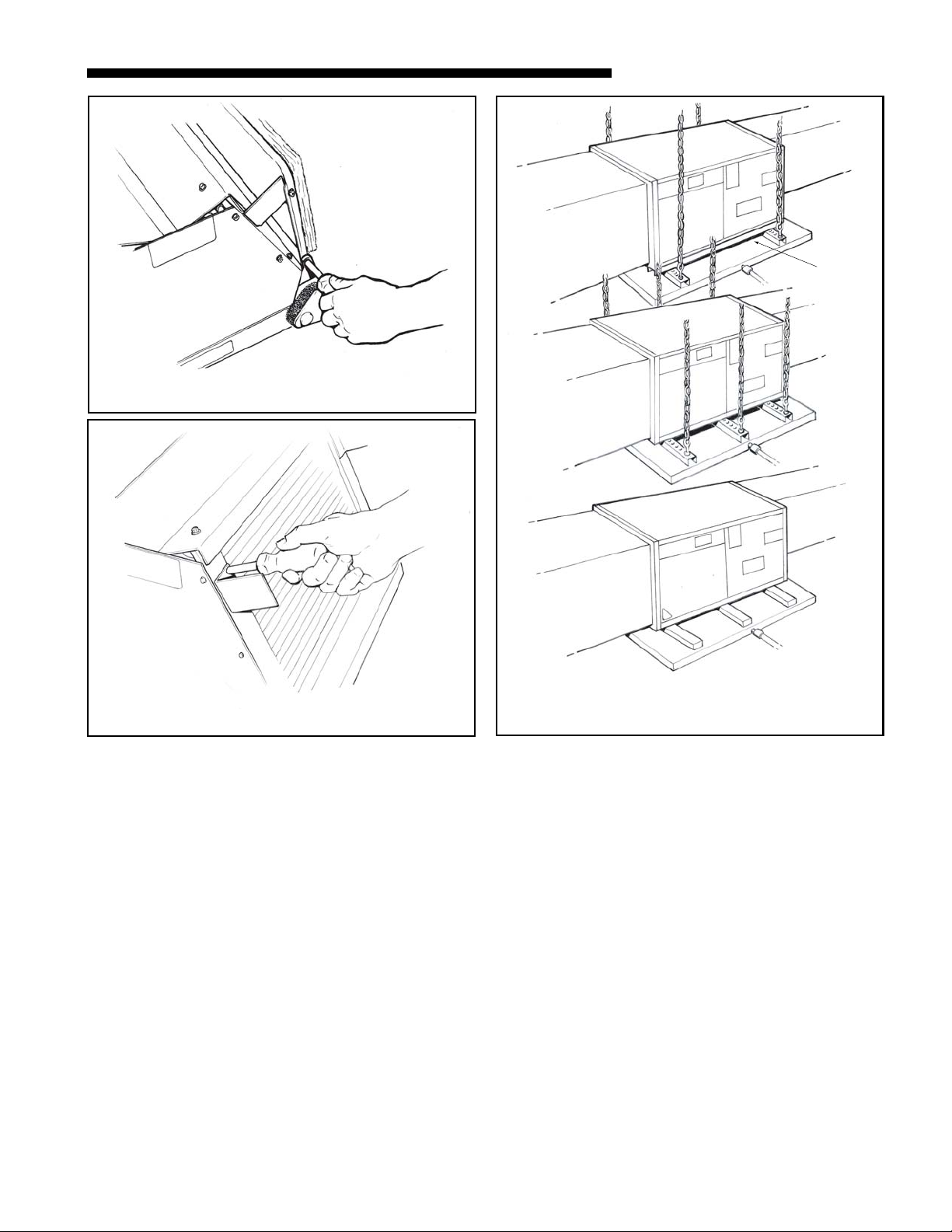
Figure 11 Horizontal Drip Tray Removal
Installer’s Guide
Rail
Figure 12 Drip Tray Bracket Removal
h. Remove the front triangular baffle from the coil
and install the 1/2" wide gasket provided per Figure 14. Trim the gasket length to fit the baffle.
Reinstall the baffle to coil, with gasket material
compressed against the coil.
i. Install the water blow-off baffles provided on each
side of the coil with the flange at the top as
shown in Figure 14. The bottom of the baffle is to
be as close to the bottom of the coil as possible.
j. Install the 7/8" wide gasket in each side of the
drain pan as shown in Figure 14 (sect. X-X).
k. The 5 ton model (2/4TEE3D65) requires 2 water
diverter baffles to be placed underneath the coil
on the inside edge of the drain pan. See Figure
14. Fill the bend in the baffle which fits the inner edge of the drain pan with non-acetic acid
RTV type adhesive/sealant before installing the
Figure 13 Mounting Installation Options
baffle. Ensure sealant is dry/set before reinstalling the coil.
l. The unit is then placed with the blower side
down and the coil is replaced on the coil channel
supports with the drain connections at the bottom. The unit is now in downflow position with
front access. Do not reattach coil support tab.
m. When supplementary heaters are used, accessory
subbase (TAYBASE101 for 2/4TEE3D31, TAYBASE100 for 2/4TEE3D37, and TAYBASE102 for
2/4TEE3D40-65) must be used. See Figure 1.
n. If a return duct is connected to the air handler, it
must be the same dimensions as the return
opening shown in the outline drawing on page
20.
o. On units with sheet metal returns: Return
plenum must be flanged. Sheetmetal screws
must be 1/2" in length or shorter. Self-tapping screws are supplied with the unit in
accessory packet. See Figure 17.
18-GE10D1-5 7
Installer’s Guide
Figure 14 DOWNFLOW BAFFLE KIT
DISCARD
DRIP TRAY
SCREWS TO
REMOVE COIL
7/8" GASKET
SECT. X-X
(TYP. BOTH SIDES)
WATER
BLOW-OFF
BAFFLES
ATTACH WITH
2 SCREWS
EACH SIDE
7/8" GASKET
X
X
1/2" GASKET
INSIDE SURFACE
OF BAFFLE
WATER
DIVERTER
BAFFLES
(5-ton only)
TRIANGULAR
BAFFLE
FRONT
SHIELD
SCREWS TO
REMOVE COIL
p. No sheetmetal screws may be used to at-
tach return ductwork on the side of the
unit.
q. Install FIELD CHARGER as shown in Figure 18
(Downflow). Ionizing pins must face upward (into
the return air stream) and electrical contacts
must be on the right side of the unit.
r. Reinstall FIELD CHARGER retainer bracket.
s. Install COLLECTION CELL as shown in Figure
18 (Downflow) so that electrical contacts and actuator tab are on the right side of the unit.
t. Install filter panel with thumbscrews.
u. Openings where field wiring enters the
cabinet must be completely sealed. Location
of power entry is shown on the outline drawing.
FILL WITH SEALANT
For Maximum Efficiency
Use 2.5" clear stickers provided to seal all unused
electrical knockouts. See Figure 16.
v. After ductwork connections are made, seal air-
tight and per Local codes.
HORIZONTAL LEFT
on
Horizontal Left,
Upflow and Downflow
Remove
and
Discard
Figure 15
Replace
with
Narrow
Baffle
8 18-GE10D1-5
 Loading...