

American Standard 4A6V0036A1000B, 4A7V0036B1000B, 4A6V0060A1000B, 4A7V0024A1000B, 4A6V0048A1000B Service Facts
...
Scan to see help
videos on this
product
Service Facts
Variable Speed AccuLink™™
Heat Pumps and Air Conditioners
4A6V0024A1000B
4A6V0036A1000B
4A6V0048A1000B
4A6V0060A1000B
4A7V0024A1000B
4A7V0036B1000B
4A7V0048A1000B
4A7V0060A1000B
4A7V0061A1000B
NNoottee:: “Graphics in this document are for representation only.
Actual model may differ in appearance.”
SSAAFFEETTYY WWAARRNNIINNGG
Only qualified personnel should install and service the equipment. The installation, starting up, and servicing of heating, ventilating, and
air-conditioning equipment can be hazardous and requires specific knowledge and training. Improperly installed, adjusted or altered
equipment by an unqualified person could result in death or serious injury. When working on the equipment, observe all precautions in the
literature and on the tags, stickers, and labels that are attached to the equipment.
August 2017
44AA--VV00--SSFF--11GG--EENN
SAFETY SECTION — OUTDOOR
IImmppoorrttaanntt — This document contains a wiring diagram
and service information. This is customer property and
is to remain with this unit. Please return to service
information pack upon completion of work.
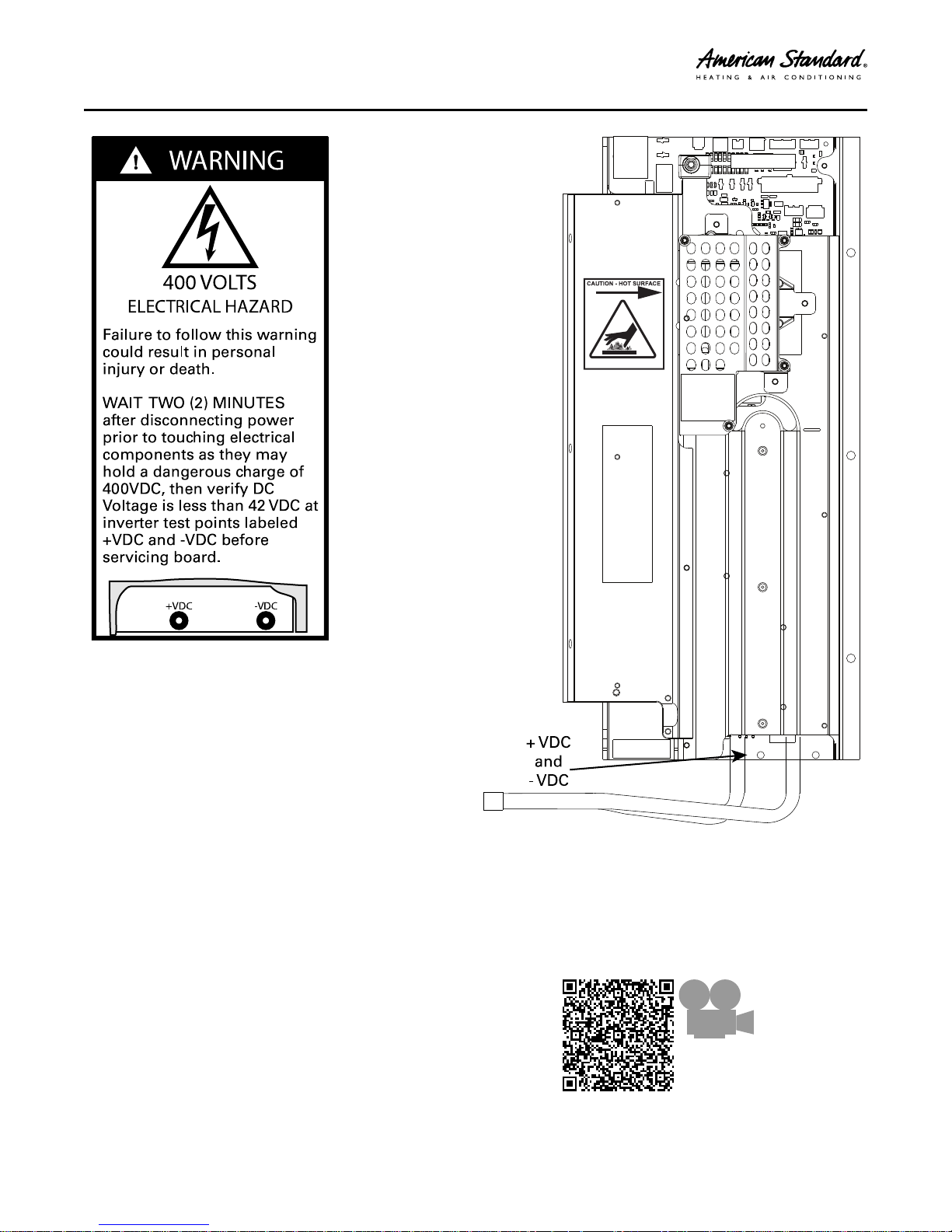
WWAARRNNIINNGG
HHAAZZAARRDDOOUUSS VVOOLLTTAAGGEE!!
FFaaiilluurree ttoo ffoollllooww tthhiiss WWaarrnniinngg ccoouulldd rreessuulltt iinn
pprrooppeerrttyy ddaammaaggee,, sseevveerree ppeerrssoonnaall iinnjjuurryy,, oorr
ddeeaatthh..
DDiissccoonnnneecctt aallll eelleeccttrriicc ppoowweerr,, iinncclluuddiinngg rreemmoottee
ddiissccoonnnneeccttss bbeeffoorree sseerrvviicciinngg.. FFoollllooww pprrooppeerr
lloocckkoouutt//ttaaggoouutt pprroocceedduurreess ttoo eennssuurree tthhee ppoowweerr
ccaannnnoott bbee iinnaaddvveerrtteennttllyy eenneerrggiizzeedd..
WWAARRNNIINNGG
RREEFFRRIIGGEERRAANNTT OOIILL!!
AAnnyy aatttteemmpptt ttoo rreeppaaiirr aa cceennttrraall aaiirr ccoonnddiittiioonniinngg
pprroodduucctt mmaayy rreessuulltt iinn pprrooppeerrttyy ddaammaaggee,, sseevveerree
ppeerrssoonnaall iinnjjuurryy,, oorr ddeeaatthh..
TThheessee uunniittss uussee RR--441100AA rreeffrriiggeerraanntt wwhhiicchh ooppeerraatteess
aatt 5500 ttoo 7700%% hhiigghheerr pprreessssuurreess tthhaann RR--2222.. UUssee oonnllyy
RR--441100AA aapppprroovveedd sseerrvviiccee eeqquuiippmmeenntt.. RReeffrriiggeerraanntt
ccyylliinnddeerrss aarree ppaaiinntteedd aa ““RRoossee”” ccoolloorr ttoo iinnddiiccaattee
tthhee ttyyppee ooff rreeffrriiggeerraanntt aanndd mmaayy ccoonnttaaiinn aa ““ddiipp””
ttuubbee ttoo aallllooww ffoorr cchhaarrggiinngg ooff lliiqquuiidd rreeffrriiggeerraanntt iinnttoo
tthhee ssyysstteemm.. AAllll RR--441100AA ssyysstteemmss wwiitthh vvaarriiaabbllee
ssppeeeedd ccoommpprreessssoorrss uussee aa PPVVEE ooiill tthhaatt rreeaaddiillyy
aabbssoorrbbss mmooiissttuurree ffrroomm tthhee aattmmoosspphheerree.. TToo lliimmiitt
tthhiiss ““hhyyggrroossccooppiicc”” aaccttiioonn,, tthhee ssyysstteemm sshhoouulldd
rreemmaaiinn sseeaalleedd wwhheenneevveerr ppoossssiibbllee.. IIff aa ssyysstteemm hhaass
bbeeeenn ooppeenn ttoo tthhee aattmmoosspphheerree ffoorr mmoorree tthhaann 44
hhoouurrss,, tthhee ccoommpprreessssoorr ooiill mmuusstt bbee rreeppllaacceedd.. NNeevveerr
bbrreeaakk aa vvaaccuuuumm wwiitthh aaiirr aanndd aallwwaayyss cchhaannggee tthhee
ddrriieerrss wwhheenn ooppeenniinngg tthhee ssyysstteemm ffoorr ccoommppoonneenntt
rreeppllaacceemmeenntt..
CCAAUUTTIIOONN
HHOOTT SSUURRFFAACCEE!!
MMaayy ccaauussee mmiinnoorr ttoo sseevveerree bbuurrnniinngg.. FFaaiilluurree ttoo
ffoollllooww tthhiiss CCaauuttiioonn ccoouulldd rreessuulltt iinn pprrooppeerrttyy
ddaammaaggee oorr ppeerrssoonnaall iinnjjuurryy..
DDoo nnoott ttoouucchh ttoopp ooff ccoommpprreessssoorr..
CCAAUUTTIIOONN
CCOONNTTAAIINNSS RREEFFRRIIGGEERRAANNTT!!
FFaaiilluurree ttoo ffoollllooww pprrooppeerr pprroocceedduurreess ccaann rreessuulltt iinn
ppeerrssoonnaall iillllnneessss oorr iinnjjuurryy oorr sseevveerree eeqquuiippmmeenntt
ddaammaaggee..
SSyysstteemm ccoonnttaaiinnss ooiill aanndd rreeffrriiggeerraanntt uunnddeerr hhiigghh
pprreessssuurree.. RReeccoovveerr rreeffrriiggeerraanntt ttoo rreelliieevvee pprreessssuurree
bbeeffoorree ooppeenniinngg ssyysstteemm..
CCAAUUTTIIOONN
GGRROOUUNNDDIINNGG RREEQQUUIIRREEDD!!
FFaaiilluurree ttoo iinnssppeecctt oorr uussee pprrooppeerr sseerrvviiccee ttoooollss mmaayy
rreessuulltt iinn eeqquuiippmmeenntt ddaammaaggee oorr ppeerrssoonnaall iinnjjuurryy..
RReeccoonnnneecctt aallll ggrroouunnddiinngg ddeevviicceess.. AAllll ppaarrttss ooff tthhiiss
pprroodduucctt tthhaatt aarree ccaappaabbllee ooff ccoonndduuccttiinngg eelleeccttrriiccaall
ccuurrrreenntt aarree ggrroouunnddeedd.. IIff ggrroouunnddiinngg wwiirreess,, ssccrreewwss,,
ssttrraappss,, cclliippss,, nnuuttss,, oorr wwaasshheerrss uusseedd ttoo ccoommpplleettee aa
ppaatthh ttoo ggrroouunndd aarree rreemmoovveedd ffoorr sseerrvviiccee,, tthheeyy mmuusstt
bbee rreettuurrnneedd ttoo tthheeiirr oorriiggiinnaall ppoossiittiioonn aanndd pprrooppeerrllyy
ffaasstteenneedd..
WWAARRNNIINNGG
SSEERRVVIICCEE VVAALLVVEESS!!
FFaaiilluurree ttoo ffoollllooww tthhiiss wwaarrnniinngg wwiillll rreessuulltt iinn aabbrruupptt
rreelleeaassee ooff ssyysstteemm cchhaarrggee aanndd mmaayy rreessuulltt iinn
ppeerrssoonnaall iinnjjuurryy aanndd//oorr pprrooppeerrttyy ddaammaaggee..
EExxttrreemmee ccaauuttiioonn sshhoouulldd bbee eexxeerrcciisseedd wwhheenn
ooppeenniinngg tthhee LLiiqquuiidd LLiinnee SSeerrvviiccee VVaallvvee.. TTuurrnn vvaallvvee
sstteemm ccoouunntteerrcclloocckkwwiissee oonnllyy uunnttiill tthhee sstteemm
ccoonnttaaccttss tthhee rroolllleedd eeddggee.. NNoo ttoorrqquuee iiss rreeqquuiirreedd..
WWAARRNNIINNGG
BBRRAAZZIINNGG RREEQQUUIIRREEDD!!
FFaaiilluurree ttoo iinnssppeecctt lliinneess oorr uussee pprrooppeerr sseerrvviiccee ttoooollss
mmaayy rreessuulltt iinn eeqquuiippmmeenntt ddaammaaggee oorr ppeerrssoonnaall
iinnjjuurryy..
iiff uussiinngg eexxiissttiinngg rreeffrriiggeerraanntt lliinneess mmaakkee cceerrttaaiinn tthhaatt
aallll jjooiinnttss aarree bbrraazzeedd,, nnoott ssoollddeerreedd..
WWAARRNNIINNGG
HHIIGGHH LLEEAAKKAAGGEE CCUURRRREENNTT!!
FFaaiilluurree ttoo ffoollllooww tthhiiss WWaarrnniinngg ccoouulldd rreessuulltt iinn
pprrooppeerrttyy ddaammaaggee,, sseevveerree ppeerrssoonnaall iinnjjuurryy,, oorr
ddeeaatthh..
EEaarrtthh ccoonnnneeccttiioonn eesssseennttiiaall bbeeffoorree ccoonnnneeccttiinngg
eelleeccttrriiccaall ssuuppppllyy..
©2017 Ingersoll Rand
4A-V0-SF-1G-EN
Scan to see an
overview
video
about the IVSC
Board
SSAAFFEETTYY SSEECCTTIIOONN —— OOUUTTDDOOOORR
Approved Combinations for Variable Speed Units
• AZONE 850 Comfort Control, or AZONE 950 with Software Version
3.0 or Higher
• TAM8C or later models
• Platinum SV Furnace
• Platinum ZV Furnace
• Approved System Accessories
Note: See AHRI directory for approved indoor and outdoor model
combinations. Only Trane coils and air handlers are approved
for use with variable speed outdoor units.
4A-V0-SF-1G-EN
Important: Use caution when cleaning outdoor coil to ensure no
water enters the electrical control compartment. When
cleaning coil from inside the compressor compartment,
take special care not to spray water towards the top rows
of the coil near the control panel. Water may enter the
control compartment and drive damaging the
electronics. Disconnect all electric power, including
remote disconnects before servicing.
3
SSAAFFEETTYY SSEECCTTIIOONN —— OOUUTTDDOOOORR
Table 1. Operating Range
Cooling 55° F to 120° F
Table 1. Operating Range (continued)
Heating -10° F to 66° F
4
4A-V0-SF-1G-EN
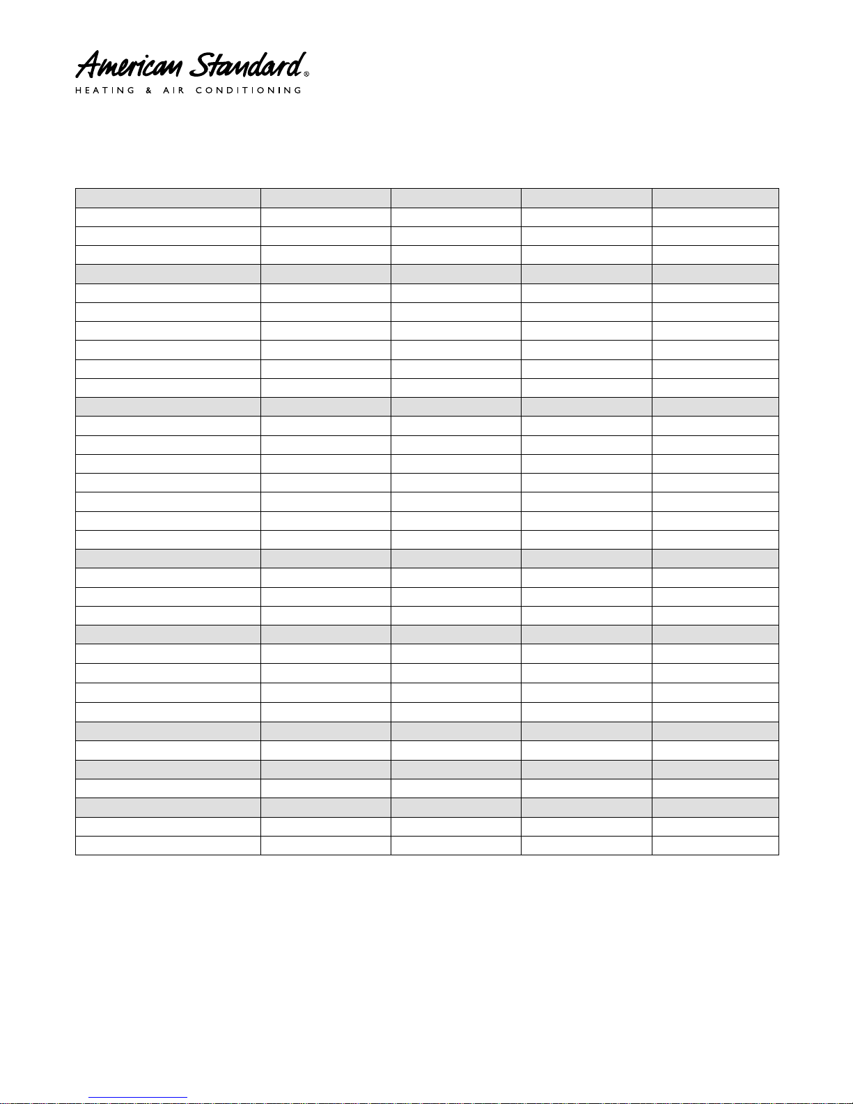
Product Specifications
HEAT PUMP MODELS
OUTDOOR UNIT
POWER CONNS. — V/PH/HZ
MIN. BRCH. CIR. AMPACITY 17.0 26.0 29.0 37.0
BR. CIR. PROT. RTG. — MAX. (AMPS)
COMPRESSOR SCROLL SCROLL SCROLL SCROLL
NO. USED — NO. SPEEDS 1–VARIABLE 1–VARIABLE 1–VARIABLE 1–VARIABLE
R.L. AMPS
FACTORY INSTALLED
START COMPONENTS
INSULATION/SOUND BLANKET
COMPRESSOR HEAT YES YES YES YES
OUTDOOR FAN
DIA. (IN.) — NO. USED
TYPE DRIVE — NO. SPEEDS DIRECT — VARIABLE DIRECT — VARIABLE DIRECT — VARIABLE DIRECT — VARIABLE
CFM @ 0.0 IN. W.G.
NO. MOTORS — HP
MOTOR SPEED R.P.M. 200 — 1200 200 — 1200 200 — 1200 200 — 1200
VOLTS/PH/HZ 208/230/1/60 208/230/1/60 208/230/1/60 208/230/1/60
F.L. AMPS 2.8 2.8 2.8 2.8
OUTDOOR COIL — TYPE SPINE FIN™ SPINE FIN™ SPINE FIN™ SPINE FIN™
ROWS — F.P.I. 1 — 24 1 — 24 1 — 24 1 — 24
FACE AREA (SQ. FT.)
TUBE SIZE (IN.)
REFRIGERANT R410–A R410–A R410–A R410–A
LBS. — R-410A (O.D. UNIT)
FACTORY SUPPLIED YES YES YES YES
LINE SIZE — IN. O.D. GAS
LINE SIZE — IN. O.D. LIQ.
CHARGING SPECIFICATIONS
SUBCOOLING 10° 9° 10° 10°
DIMENSIONS H X W X D H X W X D H X W X D H X W X D
CRATED (IN.)
WEIGHT
SHIPPING (LBS.)
NET (LBS.)
(a)
Certified in accordance with the Air-Source Unitary Air-conditioner Equipment certification program, which is based on AHRI standard 210/240.
(b)
Rated in accordance with AHRI standard 270/275.
(c)
Calculated in accordance with Natl. Elec. Codes. Use only HACR circuit breakers or fuses.
(d)
This value shown for compressor RLA on the unit nameplate and on this specification sheet is used to compute minimum branch circuit ampacity and max.
fuse size. The value shown is the branch circuit selection current.
(e)
No means no start components. Yes means quick start kit components. PTC means positive temperature coefficient starter.
(f)
Standard Air — Dry Coil — Outdoor
(g)
This value approximate. For more precise value see unit nameplate.
(h)
Max. linear length 150 ft.; Max. lift — Suction 50 ft.; Max. lift — Liquid 50 ft.
(i)
Max length of refrigerant lines from outdoor to indoor unit MUST NOT exceed 80 feet. The max vertical change MUST NOT exceed 10 feet. See footnote (h)
if 7/8” suction line is used.
(a) (b)
(d)
— L.R. AMPS
4A6V0024A1000B 4A6V0036A1000B 4A6V0048A1000B 4A6V0060A1000B
(c)
208/230/1/60 208/230/1/60 208/230/1/60 208/230/1/60
25 40 45 50
11.5 — 10.2 18.4 — 10.2 21.1 — 12.0 27.5 — 12.0
(e)
NA NA NA NA
YES YES YES YES
23 — 1 27.5 — 1 27.5 — 1 27.5 — 1
(f)
2680 3670 4517 4757
1 — 1/3 1 — 1/3 1 — 1/3 1 — 1/3
19.77 27.87 27.87 30.80
3/8 3/8 3/8 3/8
(g)
(h)
7 lb — 6 oz 9 lb — 8 oz 10 lb — 12 oz 11 lb — 14 oz
5/8
(h)
3/4
(h)
7/8
(h)
1 – 1/8
(i)
3/8 3/8 3/8 3/8
46 X 30.1 X 33 46.4 X 35.1 X 38.7 46.4 X 35.1 X 38.7 51 X 35.1 X 38.7
225 263 275 285
204 238 250 259
4A-V0-SF-1G-EN
5

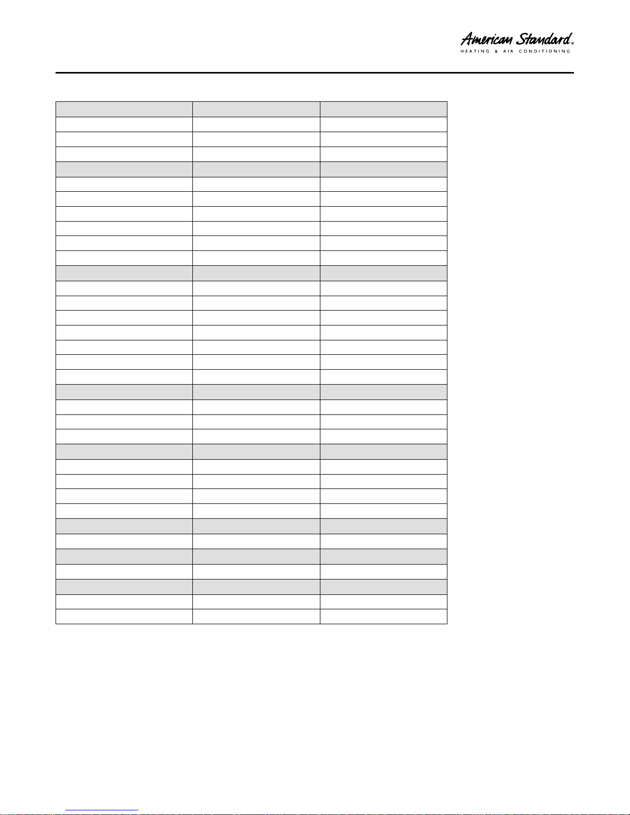
PPrroodduucctt SSppeecciiffiiccaattiioonnss
AIR CONDITIONER MODELS
OUTDOOR UNIT
POWER CONNS. — V/PH/HZ
MIN. BRCH. CIR. AMPACITY 17.0 18.0 23.0
BR. CIR. PROT. RTG. — MAX. (AMPS)
COMPRESSOR SCROLL SCROLL SCROLL
NO. USED — NO. SPEEDS 1–VARIABLE 1–VARIABLE 1–VARIABLE
R.L. AMPS
FACTORY INSTALLED
START COMPONENTS
INSULATION/SOUND BLANKET
COMPRESSOR HEAT YES YES YES
OUTDOOR FAN
DIA. (IN.) — NO. USED
TYPE DRIVE — NO. SPEEDS DIRECT — VARIABLE DIRECT — VARIABLE DIRECT — VARIABLE
CFM @ 0.0 IN. W.G.
NO. MOTORS — HP
MOTOR SPEED R.P.M. 200 — 1200 200 — 1200 200 — 1200
VOLTS/PH/HZ 208/230/1/60 208/230/1/60 208/230/1/60
F.L. AMPS 2.8 2.8 2.8
OUTDOOR COIL — TYPE SPINE FIN™ SPINE FIN™ SPINE FIN™
ROWS — F.P.I. 1 — 24 1 — 24 1 — 24
FACE AREA (SQ. FT.)
TUBE SIZE (IN.)
REFRIGERANT R410–A R410–A R410–A
LBS. — R-410A (O.D. UNIT)
FACTORY SUPPLIED YES YES YES
LINE SIZE — IN. O.D. GAS
LINE SIZE — IN. O.D. LIQ.
CHARGING SPECIFICATIONS
SUBCOOLING 10° 10° 10°
DIMENSIONS H X W X D H X W X D H X W X D
CRATED (IN.)
WEIGHT
SHIPPING (LBS.)
NET (LBS.)
(a)
Certified in accordance with the Air-Source Unitary Air-conditioner Equipment certification program, which is based on AHRI standard 210/240.
(b)
Rated in accordance with AHRI standard 270/275.
(c)
Calculated in accordance with Natl. Elec. Codes. Use only HACR circuit breakers or fuses.
(d)
This value shown for compressor RLA on the unit nameplate and on this specification sheet is used to compute minimum branch circuit ampacity and max.
fuse size. The value shown is the branch circuit selection current.
(e)
No means no start components. Yes means quick start kit components. PTC means positive temperature coefficient starter.
(f)
Standard Air — Dry Coil — Outdoor
(g)
This value approximate. For more precise value see unit nameplate.
(h)
Max. linear length 150 ft.; Max. lift — Suction 50 ft.; Max. lift — Liquid 50 ft.
(a) (b)
(d)
— L.R. AMPS
4A7V0024A1000B 4A7V0036B1000B 4A7V0048A1000B
(c)
208/230/1/60 208/230/1/60 208/230/1/60
25 25 35
11.5 — 10.2 12.4 — 10.2 16.0 — 12.0
(e)
NA NA NA
YES YES YES
23 — 1 23 — 1 27.5 — 1
(f)
2680 2850 4560
1 — 1/3 1 — 1/3 1 — 1/3
19.77 23.75 27.87
3/8 3/8 3/8
(g)
(h)
7 lb — 6 oz 9 lb — 6 oz 11 lb — 1 oz
5/8
(h)
3/4
(h)
7/8
(h)
3/8 3/8 3/8
46 X 30.1 X 33 46.4 X 35.1 X 38.7 46.4 X 35.1 X 38.7
217 248 270
196 225 245
6
4A-V0-SF-1G-EN
PPrroodduucctt SSppeecciiffiiccaattiioonnss
AIR CONDITIONER MODELS
OUTDOOR UNIT
POWER CONNS. — V/PH/HZ
MIN. BRCH. CIR. AMPACITY 27.0 27.0
BR. CIR. PROT. RTG. — MAX. (AMPS)
COMPRESSOR SCROLL SCROLL
NO. USED — NO. SPEEDS 1–VARIABLE 1–VARIABLE
R.L. AMPS
FACTORY INSTALLED
START COMPONENTS
INSULATION/SOUND BLANKET
COMPRESSOR HEAT YES YES
OUTDOOR FAN
DIA. (IN.) — NO. USED
TYPE DRIVE — NO. SPEEDS DIRECT — VARIABLE DIRECT — VARIABLE
CFM @ 0.0 IN. W.G.
NO. MOTORS — HP
MOTOR SPEED R.P.M. 200 — 1200 200 — 1200
VOLTS/PH/HZ 208/230/1/60 208/230/1/60
F.L. AMPS 2.8 2.8
OUTDOOR COIL — TYPE SPINE FIN™ SPINE FIN™
ROWS — F.P.I. 1 — 24 2 — 24
FACE AREA (SQ. FT.)
TUBE SIZE (IN.)
REFRIGERANT R410–A R410–A
LBS. — R-410A (O.D. UNIT)
FACTORY SUPPLIED YES YES
LINE SIZE — IN. O.D. GAS
LINE SIZE — IN. O.D. LIQ.
CHARGING SPECIFICATIONS
SUBCOOLING 10° 7.5°
DIMENSIONS H X W X D H X W X D
CRATED (IN.)
WEIGHT
SHIPPING (LBS.)
NET (LBS.)
(a)
Certified in accordance with the Air-Source Unitary Air-conditioner Equipment certification program, which is based on AHRI standard 210/240.
(b)
Rated in accordance with AHRI standard 270/275.
(c)
Calculated in accordance with Natl. Elec. Codes. Use only HACR circuit breakers or fuses.
(d)
This value shown for compressor RLA on the unit nameplate and on this specification sheet is used to compute minimum branch circuit ampacity and max.
fuse size. The value shown is the branch circuit selection current.
(e)
No means no start components. Yes means quick start kit components. PTC means positive temperature coefficient starter.
(f)
Standard Air — Dry Coil — Outdoor
(g)
This value approximate. For more precise value see unit nameplate.
(h)
Max length of refrigerant lines from outdoor to indoor unit MUST NOT exceed 80 feet. The max vertical change MUST NOT exceed 25 feet. See footnote (h)
if 7/8” suction line is used.
(i)
Max length of refrigerant lines from outdoor to indoor unit MUST NOT exceed 80 feet. The max vertical change MUST NOT exceed 25 feet. See footnote (h)
if 7/8" suction line is used.
(a) (b)
(d)
— L.R. AMPS
4A7V0060A1000B 4A7V0061A1000B
(c)
208/230/1/60 208/230/1/60
40 40
19.3 — 12.0 19.3 — 12.0
(e)
NA NA
YES YES
27.5 — 1 27.5 — 1
(f)
4787 4780
1 — 1/3 1 — 1/3
30.80 30.80
3/8 3/8
(g)
(h)
11 lb — 14 oz 12 lb — 7 oz
1 — 1/8
(h)
1–1/8
(i)
3/8 3/8
51 X 35.1 X 38.7 51 X 35.1 X 38.7
284 314
258 288
4A-V0-SF-1G-EN
7

Subcooling Charging in Cooling between 55°° F and 120°°
OD Ambient
American Standard has always recommended
installing American Standard approved matched
indoor and outdoor systems.
All American Standard split systems are AHRI rated
with only TXV or EEV indoor systems.
The benefits of installing approved indoor and outdoor
split systems are maximum efficiency, optimum
performance and the best overall reliability.
The following charging methods are therefore
prescribed for matched systems with indoor TXVs or
EEVs.
1. Subcooling (in the cooling mode) is the only
recommended method of charging between 55°
and 120° ambient temperatures.
2. When charging for ambient temperatures above
120°, charge to 10° subcooling. It is important to
return when outdoor ambient temperature is
between 55° and 120° to verify system charge per
these instructions.
3. For best results — the indoor temperature should
be kept between 70° to 80°. Add system heat if
needed.
4. Locate the designated subcooling target from the
unit nameplate.
5. At startup, or whenever charge is removed or
added, the system must be operated for a minimum
of (20) minutes to stabilize before accurate
measurements can be made.
6. Run the system using the ““CChhaarrggiinngg MMooddee-CCoooolliinngg”” mode found in the 850/950 comfort
control. This is the only approved method for
setting the system charge level.
Measure Liquid Line Temperature and Refrigerant
Pressure at service valves.
7. Determine total refrigerant line length, and height
(lift) if indoor section is above the condenser.
Follow the Subcool Charging Corrections Table to
calculate additional subcooling target value.
8. Locate your liquid line temperature in the left
column of the table, and the intersecting liquid line
gage pressure under the subcool selection column.
Add refrigerant to raise the pressure to match the
table, or remove refrigerant to lower the pressure.
Always wait (20) minutes for the system conditions
to stabilize before adjusting charge again.
9. When system is correctly charged, you can refer to
System Pressure Curves to verify typical
performance.
8
4A-V0-SF-1G-EN
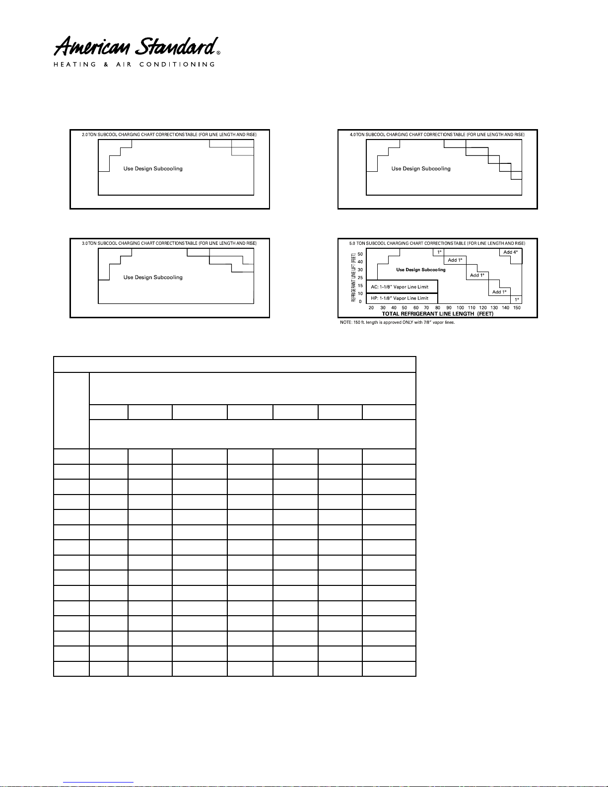
Subcool Charging Correction Charts
TOTAL REFRIGERANT LINE LENGTH (FEET)
Add 1°
Add 1°
Add 2°
70 80 90 100 110 120 130 140 1506050403020
50
40
30
25
15
10
0
REFRIGERANT LINE LIFT (FEET)
TOTAL REFRIGERANT LINE LENGTH (FEET)
Add 1°
Add 1° Add 2°
70 80 90 100 110 120 130 140 1506050403020
50
40
30
25
15
10
0
REFRIGERANT LINE LIFT (FEET)
TOTAL REFRIGERANT LINE LENGTH (FEET)
Add 1°
1°
1°
1°
Add 1°
Add 2°
70 80 90 100 110 120 130 140 1506050403020
50
40
30
25
15
10
0
REFRIGERANT LINE LIFT (FEET)
Add
2°
Figure 1. Subcool Charging Corrections — 2.0 Ton
Figure 2. Subcool Charging Corrections — 3.0 Ton
Refrigerant Charging Chart
R-410A REFRIGERANT CHARGING CHART
DESIGN SUBCOOLING (°F)
LIQUID
TEMP
(°F)
8 9 10 11 12 13 14
LIQUID GAGE PRESSURE (PSI)
Figure 3. Subcool Charging Corrections — 4.0 Ton
Figure 4. Subcool Charging Corrections — 5.0 Ton
55 179 182 185 188 191 195 198
60 195 198 201 204 208 211 215
65 211 215 218 222 225 229 232
70 229 232 236 240 243 247 251
75 247 251 255 259 263 267 271
80 267 271 275 279 283 287 291
85 287 291 296 300 304 309 313
90 309 313 318 322 327 331 336
95 331 336 341 346 351 355 360
100 355 360 365 370 376 381 386
105 381 386 391 396 402 407 413
110 407 413 418 424 429 435 441
115 435 441 446 452 458 464 470
120 464 470 476 482 488 495 501
125 495 501 507 514 520 527 533
4A-V0-SF-1G-EN
9
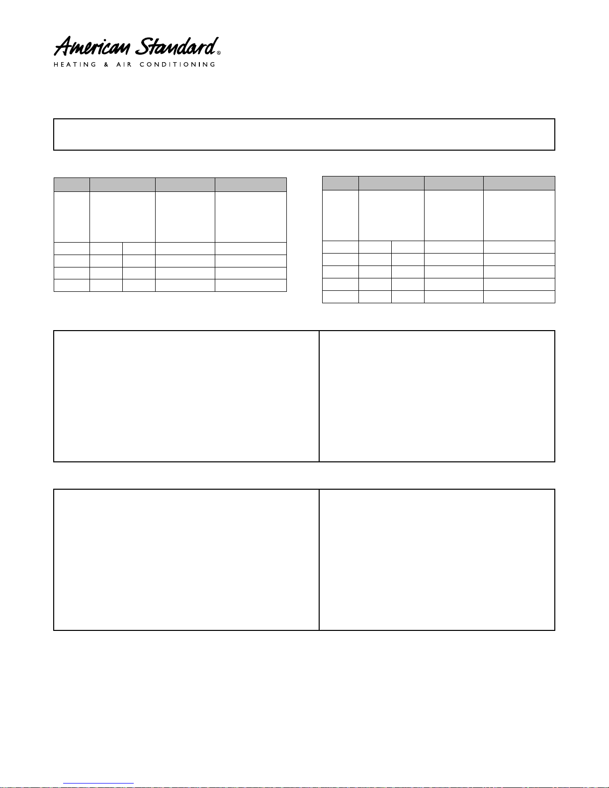
Charging: Weigh-In Method
Weigh-In Method can be used for the initial installation, or anytime a system charge is being replaced. Weigh-In Method can also be used when
power is not available to the equipment site or operating conditions (indoor/outdoor temperatures) are not in range to verify with the
subcooling charging method.
Table 2. Heat Pumps
A
B C D
Table 3. Air Conditioners
A
Charge
multiplier for
interconnecting
refrigerant
Model
Model
Factory
Charge
Charge
adder for
Indoor Coil
tube length
024 7 lb. 6 oz. 6 oz.
036 9 lb. 8 oz. 12 oz.
048 10 lb. 12 oz. 15 oz.
060 11 lb. 14 oz.
1 lb., 2 oz. 0.6 oz/ft
0.6 oz/ft
0.6 oz/ft
0.6 oz/ft
024 7 lb. 6 oz. 6 oz.
036 9 lb. 6 oz. 12 oz.
048 11 lb. 1 oz.
060 11 lb. 14 oz.
061 12 lb. 7 oz.
Table 4. New Installations — Calculating Charge using the Weigh-In method
1. Measure in feet the distance between the outdoor unit and the indoor
unit and record on Line 1. Include the entire length of the line from the
service valve to the IDU.
2. Enter the charge multiplier from Column D.
3. Multiply the total length of refrigerant tubing (Line 1) times the value on
Step 2. Record the result on Line 3 of the Worksheet.
4. Locate the outdoor equipment size in Column A. Record the value shown
in Column C of Table 16 for Heat Pumps or Table 17 for Air Conditioners.
5. Add the values from Step 3 and Step 4 and record the resulting value.
This is the amount of refrigerant to weigh-in prior to opening the service
valves.
New Installation Weigh-In Method Worksheet
1. Line Length (ft) ________________________
2. Value from Column D x ________________________
3. Step 1 x Step 2 = ________________________
4. Charge Adder (column C) + ________________________
5. Refrigerant (Steps 3+4) = ________________________
B C D
Factory
Charge
Charge
adder for
Indoor Coil
1 lb., 0 oz. 0.6 oz/ft
1 lb., 2 oz. 0.6 oz/ft
1 lb., 4 oz. 0.6 oz/ft
Charge
multiplier for
interconnect-
ing refrigerant
tube length
0.6 oz/ft
0.6 oz/ft
Table 5. Sealed-System Repairs — Calculating Charge using the Weigh-In method.
1. Measure in feet the distance between the outdoor unit and the indoor
unit and record on Line 1. Include the entire length of the line from the
service valve to the IDU.
2. Enter the charge multiplier from Column D.
3. Multiply the total length of refrigerant tubing (Line 1) times the value on
Line 2. Record the result on Line 3 of the Worksheet.
4. Locate the outdoor equipment size in Column A. Record the value shown
in Column C of Table 16 for Heat Pumps or Table 17 for Air Conditioners.
5. Record the value in Column B to Line 5 of the Worksheet.
6. Add the values from Step 3, Step 4, and Step 5 and record the resulting
value on Line 6. This is the amount of refrigerant to weigh-in.
Note: The only mode approved for setting or validating system charge is using Charging Mode-Cooling. Charging Mode-Cooling is a variable
speed test mode found in the 850/950 comfort control Technician Menu. Outdoor Temperature must be between 55
Indoor Temperature kept between 70
10
°
F and 80°F.
New Installation Weigh-In Method Worksheet
1. Line Length (ft) ________________________
2. Value from Column D x ________________________
3. Step 1 x Step 2 = ________________________
4. Charge Adder (column C) + ________________________
5. Factory Charge (column B) + ________________________
6. Refrigerant (Steps 3+4+5) = ________________________
°
F and 120°F with
4A-V0-SF-1G-EN
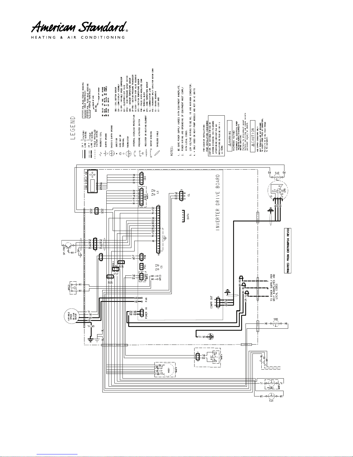
Wiring — D157619P04
4A-V0-SF-1G-EN
11
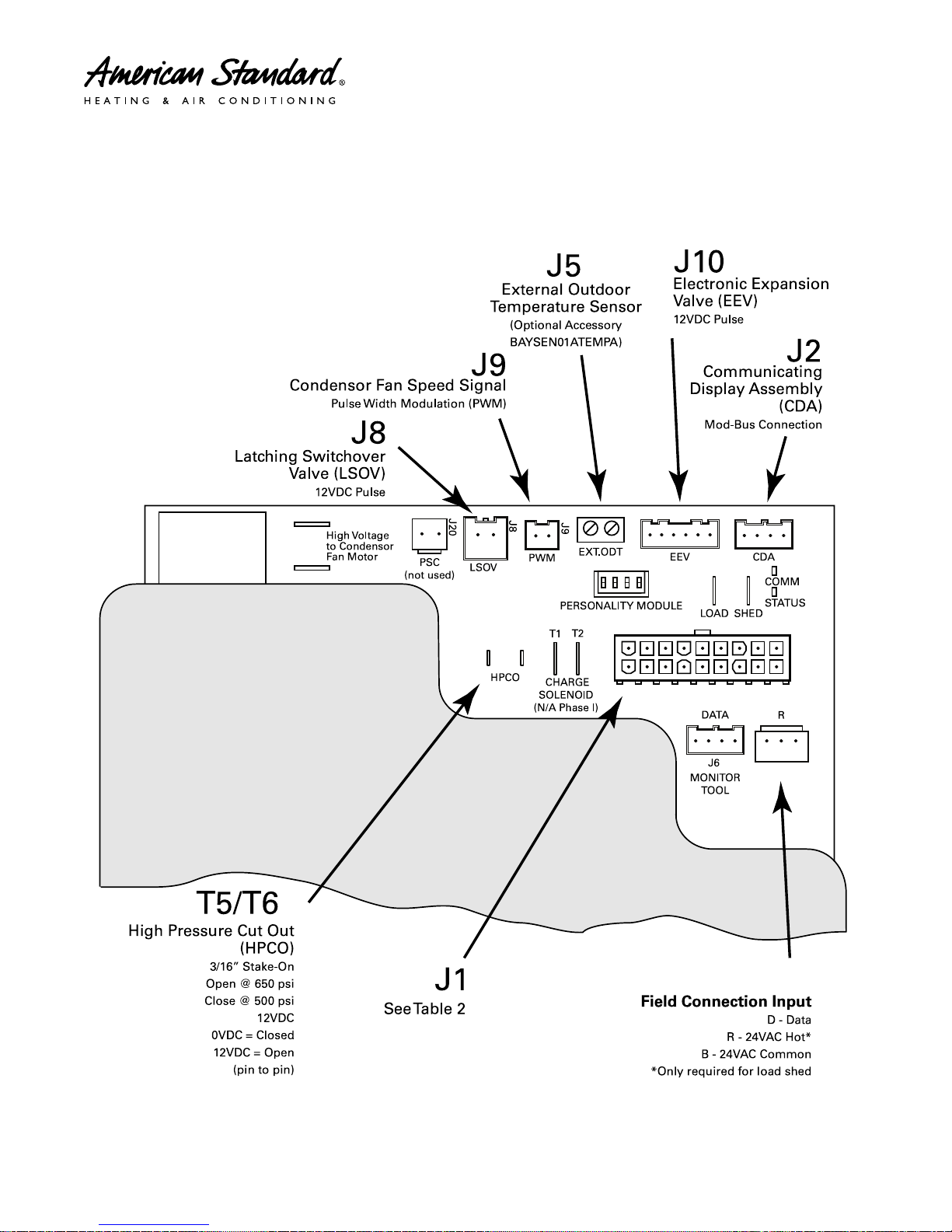
Integrated Variable Speed Control (IVSC) Inputs/
FAN
ALUMINUM COVER PLATE
T4 T3
10
1
18
9
J1
J4
D B
J3
J10
J2
J5
J4
Outputs
AAllssoo RReeffeerrrreedd ttoo aass ““TThhee DDrriivvee””
12
4A-V0-SF-1G-EN
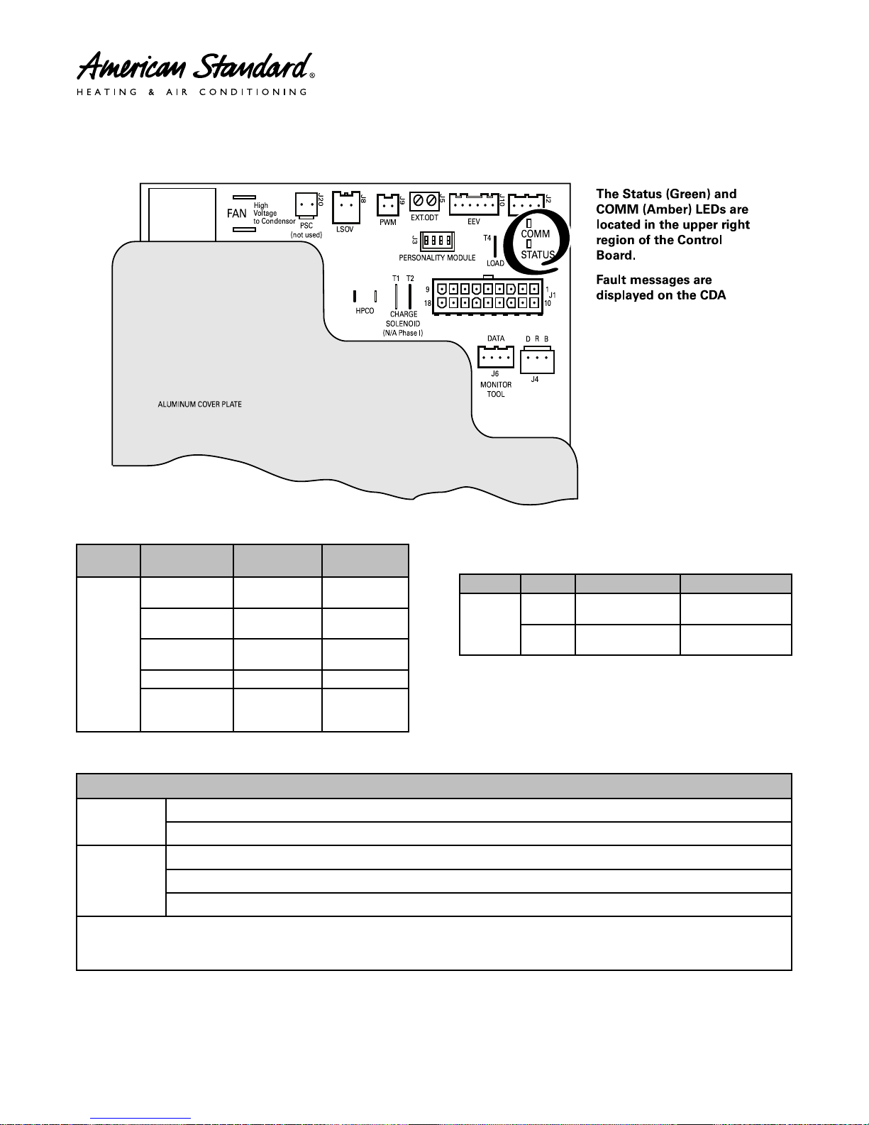
Integrated Variable Speed Control Board
SHED
CDA
STATUS
COMM
T3
LED Indicators
LLEEDD’’SS
LED RATE
MEDIUM
STATUS
(GREEN)
SOLID ON TEST MODE
INTERMITTENT
SLOW
FAST
DESCRIP-
TION
1 TIME PER
SECOND
2 TIMES PER
SECOND
5 TIMES PER
SECOND
1 FLASH
EVERY 4
SECONDS
INDICA-
TION
STANDBY/
IDLE
CALL FOR
CAPACITY
POWER UP
DELAY
HARD
LOCKOUT
LED RATE DESCRIPTION INDICATION
1 TIME PER
DEVICE
5 TIME PER
SECOND
COMM
(AMBER)
SLOW
FAST
DEVICE COUNT
LOSS OF
COMMUNICATION
Sump Heat Control
Sump Heat ON
Sump Heat
OFF
Note: Variable Speed systems are designed so that the compressor and sump heat will not run at the same time. Compressor windings are
used for sump heat. When sump heat is active, line-side current will be approximately 1.5 amps. The CDA MONITOR MENU has a field for
DRIVE >> DRIVE AMPS which can also be used to verify operation of sump heat.
4A-V0-SF-1G-EN
At power up; when outdoor temperature is below 85° F
When outdoor temperature is below 80° F and compressor dome temperature is less than the outdoor ambient temperature
When the outdoor temperature goes above 85° F (Sump Heat remains OFF until outdoor temperature drops below 80° F)
Anytime the compressor is running
For 50 minutes after each compressor run cycle.
Sump Heat Control Guidelines
13

Sequence of Operation
CCoonnttrrooll OOppeerraattiioonnaall OOvveerrvviieeww
Operation of the communicating, variable speed
outdoor unit is managed and monitored by a micro
processor based Integrated Variable Speed Control
(IVSC) located in the control box of the outdoor unit.
This component is also referred to as “The Drive”. Heat
and Cool demand messages are transmitted from the
comfort control over the data line from the comfort
control to the indoor and outdoor sections of the
system. System mode and capacity requests are
received by the outdoor IVSC and responded to by
providing control outputs to the switch-over valve
(SOV) solenoid coil, electronic expansion valve (EEV)
stepper motor, condenser fan motor and compressor.
Operating conditions and system commands such as
compressor percent demand, indoor airflow, EEV
starting position, defrost (For auxiliary heat), outdoor
temperature and alerts are transmitted from the
outdoor control over the data line to the rest of the
communicating system. Additional data that is
communicated to the rest of the system includes the
type of equipment installed (variable speed, unit size in
nominal tonnage, heat pump or air conditioner) which
is used during the Auto Discover function to set indoor
airflow and configure the comfort control for the
equipment installed
The IVSC has two Light Emitting Diodes (LED) used for
indicating operating status and verifying
communications. The STATUS LED flash rate indicates
if the system is in standby (or idle), receiving capacity
demand from the comfort control, in a test mode or in a
lockout condition. The COMM LED indicates successful
communications by flashing a device count which can
be used to verify how many communicating devices
are connected to the data line.
A Communicating Display Assembly (CDA) is
connected to the IVSC and is used to monitor,
configure, test and provide feedback about the system.
speed and hold steady for a minimum dwell period to
ensure proper oil return. This dwell period will typically
last for 1 minute but for initial start ups, after power is
first applied, the dwell period is 15 minutes. The startup
operation will progress to normal operation once this
dwell period is completed. With stage one demand and
minimum compressor RPM, the system will duty cycle
as needed to provide the required capacity requested
from the comfort control. The default duty cycle setting
for stage one demand is 3 Cycles per Hour (CPH). See
the Advanced Settings in the 850/950 Installation Guide
for more information on CPH.
With any start up, a Pulse Width Modulation (PWM)
signal is sent from the J9 plug of the IVSC to the
outdoor fan motor to run at the required matching
speed.
Should system load value rise above 100, stage two
demand is sent from the communicating comfort
control to the outdoor control and the IVSC will
respond by entering the modulating region of
compressor and outdoor fan operation. As load value
increases or decreases in the modulating region, so
will the compressor, outdoor fan and indoor blower
speeds to continuously deliver the capacity requested
by the comfort control and meet the demand of the
structural load. All indoor CFM demand messages will
be sent from the IVSC to the indoor unit so that the
blower motor will run with matching modulating
speeds. The System Report Screen (Located in the 850/
950’s Technician Access menu) or the Monitor Menu
(Located in the outdoor CDA Technicians Control
menu) can be used to view the compressor demand, in
percentage, while in the modulating range.
As system load value drops below 100, stage two
demand is satisfied and the communicating comfort
control returns system operation to stage one demand
and the system will begin to duty cycle as needed to
provide the requested capacity.
CCoooolliinngg MMooddee ((AA//CC aanndd HHeeaatt PPuummpp))
When a request for cooling capacity is sent from the
communicating comfort control to the outdoor unit, the
IVSC will respond by flashing the STATUS LED two
times per second and the CDA will display COOLING in
the SYSTEM STATUS home screen. The IVSC will
calculate the required running speed for the
compressor and outdoor fan based on the current load
value and stage demand sent from the comfort control.
Load values under 100 will generate stage one demand
and the IVSC will generate power to produce the
minimum compressor RPM. Additionally, a CFM
demand message is sent from the outdoor IVSC to the
indoor unit for matching indoor airflow.
Regardless of the load value or stage demand, the
outdoor system will start and ramp to a target startup
14
HHeeaatt PPuummpp CCoooolliinngg MMooddee ooff OOppeerraattiioonn
In addition to stage and demand operating sequences
outlined in the Cooling Mode description, when a heat
pump system receives a demand message for cooling,
the Switch Over Valve (SOV) solenoid will be pulsed to
position the valve for cooling. Latching Switch Over
Valve (LSOV) technology is standard with variable
speed outdoor heat pumps. By utilizing components
designed to hold the pilot pin of the SOV in place, the
valve will maintain the cooling or heating position even
when power is removed. Maintaining valve position, or
Latching, is accomplished with the help of a magnet
mounted in the solenoid coil or a spring manufactured
internal to the SOV. To initiate the SOV position, a12
Volt DC pulse is sent from the J8 plug located on the
IVSC to the solenoid coil at the start of each call for
capacity. Polarity of the DC pulse is critical to the
4A-V0-SF-1G-EN

SSeeqquueennccee ooff OOppeerraattiioonn
direction the valve’s pilot pin will be set. Always follow
the red and blue color coding to ensure proper polarity.
Heat pumps are also equipped with an Electronic
Expansion Valve (EEV) which will be set to the “Check
Valve Position” and drive wide open. The EEV does not
provide refrigeration control in the cooling mode of
operation.
HHeeaatt PPuummpp HHeeaattiinngg MMooddee ooff OOppeerraattiioonn
When a request for heating capacity is sent from the
communicating comfort control to the outdoor unit, the
IVSC will respond by flashing the STATUS LED two
times per second and the CDA will display HEATING in
the SYSTEM STATUS home screen.
In the heating mode of operation the LSOV solenoid
will be pulsed to position the valve for heating at the
start of each call for capacity.
During heating mode, the EEV will be in the controlling
state. Refrigerant flow is managed by incrementally
opening or closing the valve to control compressor
superheat under a wide range of conditions. Superheat
is calculated with feedback to the IVSC from a suction
line temperature sensor and a suction line pressure
transducer. The IVSC will target 10 degrees (+/-2) of
superheat and drive a valve position by periodically
pulsing the stepper motor and then monitoring
compressor superheat results. Control signals to the
EEV stepper motor are 12 volt DC pulses from J10 on
the IVSC. The EEV step position and compressor
superheat can be monitored through the CDA monitor
menu during runtime operation. The IVSC will close the
EEV with every OFF cycle and drive the valve to wide
open during defrost or cooling mode of operation.
NNoottee:: When a heat pump system is first powered up,
the EEV produces an audible sound (soft
ratcheting sound) as the valve drives to the
closed position.
DDeeffrroosstt MMooddee ffrroomm CCyycclliinngg--SSttaaggee
When the system is operating in cycling-stage and the
control initiates a Defrost, the indoor control
simultaneously:
• De-energizes the PWM signal to the outdoor fan
motor,
• Drives the OD EEV to full open and,
• Commands the SOV to change to the cooling mode.
There is a brief switchover time-delay (to allow
refrigerant pressures to stabilize) before the
compressor is commanded to run at Maximum Speed
Cooling to perform Defrost.
The outdoor control also sends a demand message to
the indoor unit to run the blower at Maximum Speed
Cooling and energize auxiliary heat (if equipped).
Auxiliary heat blower speed may be higher than
Maximum Speed Cooling and will take precedence
during defrost.
The Defrost Mode will be terminated after the OD coil
temperature reaches 47°F or the maximum time
override of 15 minutes has lapsed. At Defrost
termination, the compressor will be commanded to go
to the Defrost Switchover Speed. After the lower speed
is achieved, the SOV position will be changed back to
the heating mode of operation and the OD fan will be
turned back on. Following the refrigerant stabilizing
delay, the compressor will be allowed to run at any
speed commanded by thermostat demand.
The outdoor control will send the necessary pulse
signals to the stepper motor coil returning the EEV to a
controlling position that matches capacity demand and
begin monitoring superheat.
DDeeffrroosstt MMooddee ffrroomm MMoodduullaattiinngg--SSttaaggee
When the system is operating in modulating-stage and
the control initiates a Defrost, the outdoor control
commands the compressor to go to the Defrost
Switchover Speed.
After the lower speed is achieved, the SOV will be
switched into the cooling mode and the control will
simultaneously de-energize the PWM signal to the
outdoor fan motor and drive the OD EEV to full open.
There is a brief switchover time-delay (to allow
refrigerant pressures to stabilize) before the
compressor is commanded to run at Maximum Speed
Cooling to perform Defrost.
The outdoor control also sends a demand message to
the indoor unit to run the blower at Maximum Speed
Cooling and energize auxiliary heat (if equipped).
Auxiliary heat blower speed may be higher than
Maximum Speed Cooling and will take precedence
during defrost.
The CDA will show DEFROST in the Home Screen.
The Defrost Mode will be terminated after the OD coil
temperature reaches 47°F or the maximum time
override of 15 minutes has lapsed. At Defrost
termination, the compressor will be commanded to go
to the Defrost Switchover Speed. After the lower speed
is achieved, the SOV position will be changed back to
the heating mode of operation and the OD fan will be
turned back on. Following the refrigerant stabilizing
delay, the compressor will be allowed to run at any
speed commanded by thermostat demand.
The outdoor control will also send the necessary pulse
signals to the stepper motor coil returning the EEV to a
controlling position that matches capacity demand and
begin monitoring superheat.
The system will stay in the Defrost, Maximum Speed
Cooling even if the comfort control demand changes
from modulating-stage to cycling-stage. However, the
system will shut down if the comfort control demand
message for cycling-stage capacity ends. The system
will continue the current defrost cycle the next time the
comfort control sends a demand message for
compressor heat.
4A-V0-SF-1G-EN
15
Defrost Control (Heat Pump only)
DDeemmaanndd DDeeffrroosstt
The demand defrost control measures heat pump
outdoor ambient temperature with a sensor located
outside the outdoor coil. A second sensor located on
the outdoor coil is used to measure the coil
temperature. The difference between the ambient and
the colder coil temperature is the difference or delta-T
measurement. This delta-T measurement is
representative of the operating state and relative
capacity of the heat pump system. By measuring the
change in delta-T, we can determine the need for
defrost. The coil sensor also serves to sense outdoor
coil temperature for termination of the defrost cycle.
FFaauulltt IIddeennttiiffiiccaattiioonn
A fault condition is indicated by the CDA connected to
the control board inside the heat pump control box.
DDeeffrroosstt EEnnaabblleedd
Demand Defrost is enabled with the following inputs to
the Integrated Variable Speed Control (IVSC):
• Outdoor ambient temperature sensor (ODS-B)
reporting an outdoor temperature at or below 52° F.
• Coil temperature sensor (CBS) reporting a coil
temperature at or below 35° F.
• Heat/Cool Demand (HCD) from the communicating
comfort control for at least two minutes or more.
DDeeffrroosstt IInniittiiaattiioonn
The calculated temperature difference between the
outdoor temperature sensor and the coil temperature
sensor is called Delta T. Defrost can occur once the
current Delta T exceeds the Delta T initiate value. The
Defrost initiate value is calculated using a clean-coil
Delta T x 2.0, plus a temperature bin correction factor.
Initiation Delta T will automatically adjust based on the
outdoor temperature. This adaptive logic assures a
complete defrost for a range of outdoor temperatures.
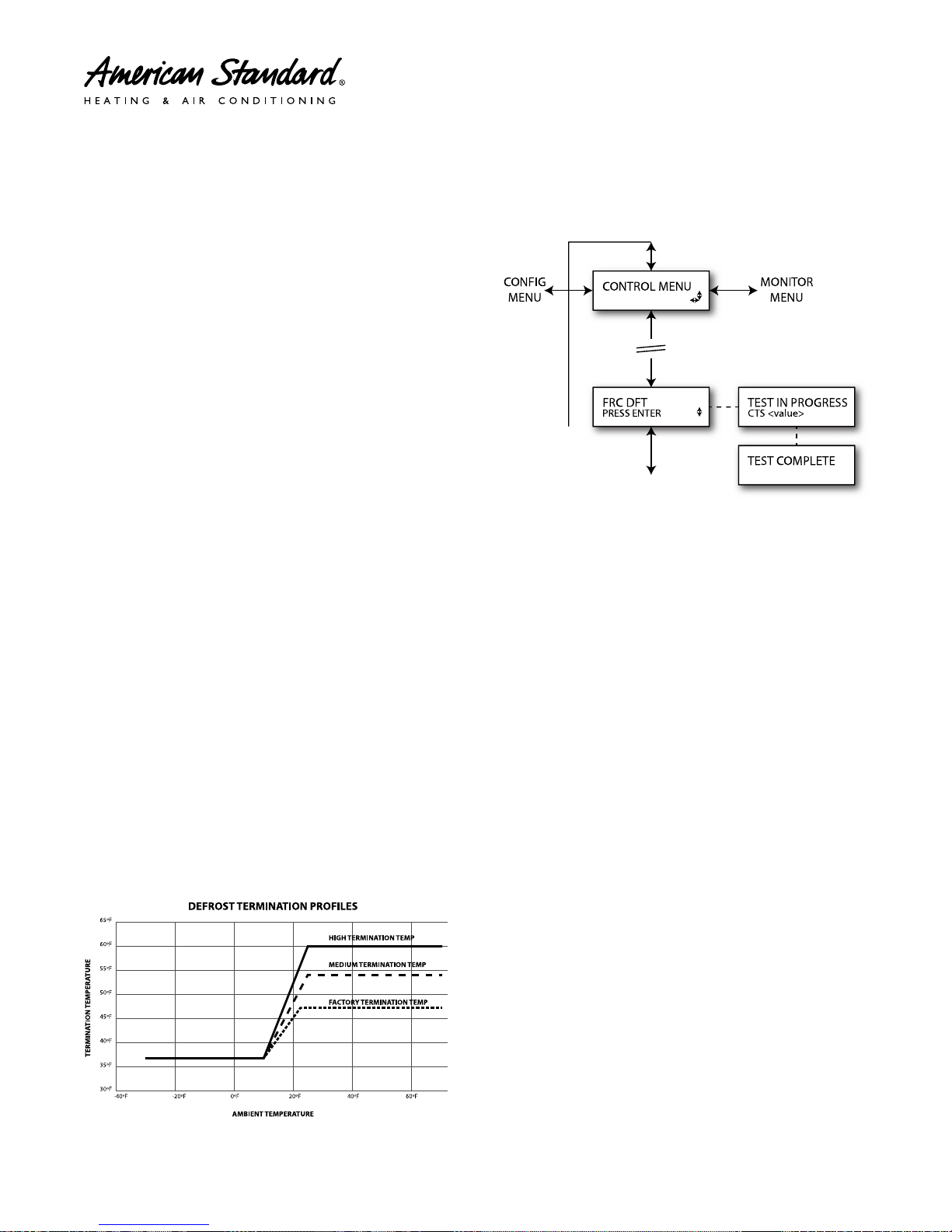
CCDDAA NNaavviiggaattiioonn ttoo FFoorrcceedd DDeeffrroosstt
Figure 5. CDA Mini Menu
NNOOTTEESS:: FFoorrcceedd DDeeffrroosstt
1. System must be running with demand from the
thermostat.
2. FRC DFT TEST can be initiated in heat mode only.
3. Press ENTER to begin forced defrost.
4. Execute Forced Defrost following Forced Defrost
(Defrost terminates on Coil Temperature or
maximum time override of 15 minutes).
5. When test begins, TEST IN PROGRESS displays on
line 1 and Coil Temperature value on line 2.
NNoottee:: Home Screen, under System Status will display
DEFROST.
6. When test is complete, TEST COMPLETE displays
for 10 seconds.
7. If there is a defrost fault condition, test terminates
and sends alert to the alert menu.
8. For more information, refer to the Alert Code Tables
in Service Facts and Technical Service Manual (Pub.
No. 34–4301–01) documents.
NNoottee:: Screens will update as the test proceeds.
16
4A-V0-SF-1G-EN
SENSORS
123456789
101112131415161718
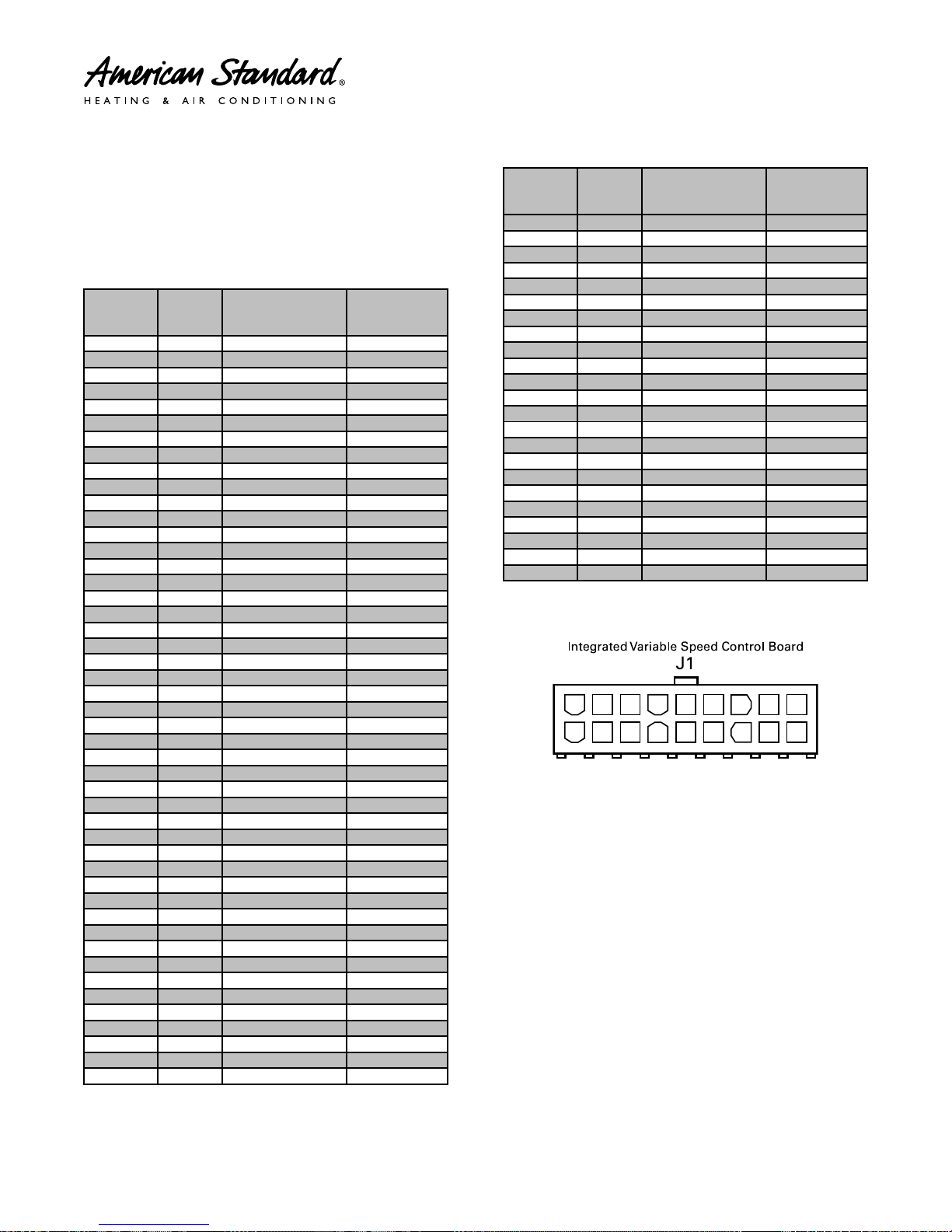
Compressor Dome Temperature
This table shows the corresponding voltage, resistance
and temperature readings for the Dome Temperature
Sensor when measured across pins 1 and 10. The
power source for the Dome Temperature Sensor is
3.2VDC.
THERMISTOR
TEMP F TEMP C
-15 -26.11 139453 3.13
-10 -23.33 118062 3.11
-5 -20.56 100258 3.10
0 -17.78 85393 3.08
5 -15.00 72944 3.06
10 -12.22 62487 3.04
15 -9.44 53676 3.02
20 -6.67 46232 2.99
25 -3.89 39925 2.96
30 -1.11 34567 2.93
35 1.67 30003 2.89
40 4.44 26105 2.85
45 7.22 22767 2.80
50 10.00 19903 2.75
55 12.78 17438 2.70
60 15.56 15312 2.64
65 18.33 13475 2.58
70 21.11 11883 2.51
75 23.89 10501 2.45
80 26.67 9298 2.37
85 29.44 8249 2.30
90 32.22 7333 2.22
95 35.00 6530 2.14
100 37.78 5826 2.06
105 40.56 5208 1.97
110 43.33 4663 1.89
115 46.11 4182 1.80
120 48.89 3758 1.72
125 51.67 3382 1.63
130 54.44 3048 1.55
135 57.22 2752 1.47
140 60.00 2488 1.39
145 62.78 2253 1.31
150 65.56 2043 1.24
155 68.33 1856 1.17
160 71.11 1688 1.10
165 73.89 1537 1.03
170 76.67 1402 0.97
175 79.44 1280 0.91
180 82.22 1170 0.85
185 85.00 1071 0.80
190 87.78 982 0.74
195 90.56 901 0.70
200 93.33 828 0.65
205 96.11 762 0.61
210 98.89 702 0.57
215 101.67 647 0.53
RESISTANCE
(OHMS)
VOLTS DC
(PIN TO PIN)
THERMISTOR
TEMP F TEMP C
220 104.44 597 0.50
225 107.22 552 0.47
230 110.00 511 0.44
235 112.78 473 0.41
240 115.56 438 0.38
245 118.33 407 0.36
250 121.11 378 0.33
255 123.89 351 0.31
260 126.67 327 0.29
265 129.44 304 0.27
270 132.22 284 0.26
275 135.00 265 0.24
280 137.78 247 0.23
285 140.56 231 0.21
290 143.33 216 0.20
295 146.11 203 0.19
300 148.89 190 0.18
305 151.67 178 0.17
310 154.44 167 0.16
315 157.22 157 0.15
320 160.00 148 0.14
325 162.78 139 0.13
330 165.56 131 0.12
RESISTANCE
(OHMS)
VOLTS DC
(PIN TO PIN)
Figure 6. Dome Temperature Sensor
Pin 1 & 10 (Red)
A working Compressor Dome Temperature Sensor is
required for:
• Protection (High/Low Temperature)
• Preheating (Sump Heat)
• Outdoor EEV Control
• Diagnostics; Reverse rotation, Flooding, Charge
Level
The Dome Temperature Sensor control contains an
NTC thermistor input for sensing the Compressor
Dome Temperature. The thermistor has a nominal
resistance of ≈ 10k ohms at 75°F. The minimum range
required for the Dome Temperature input is —31°F to
302°F. when measured across pins 1 and 10.
NNoottee:: Secure Installation of Dome Sensor is required
for reliable compressor & system operation.
4A-V0-SF-1G-EN
17
123456789
101112131415161718
SSEENNSSOORRSS
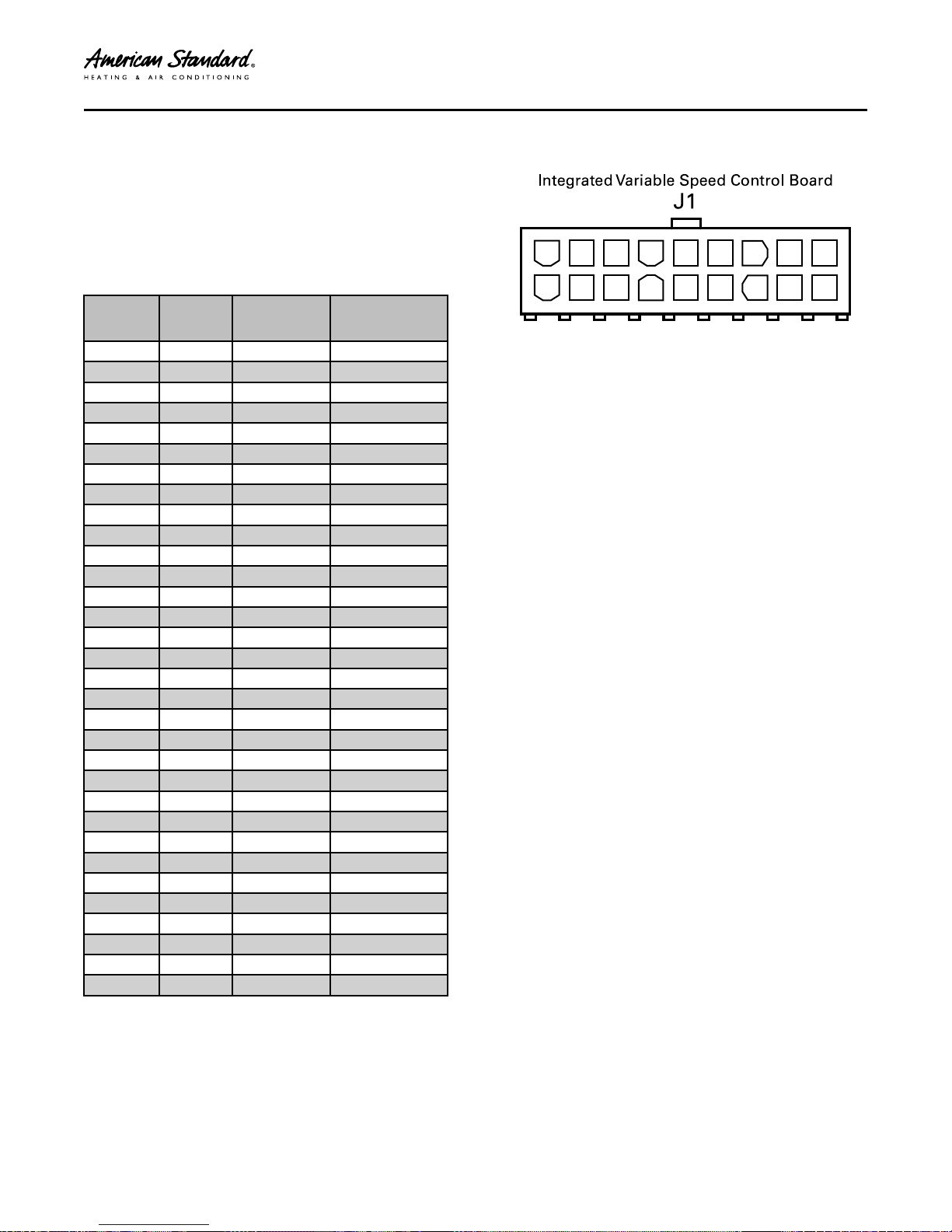
Ambient Temperature Sensor
(ODS)
These tables show the corresponding voltage,
resistance and temperature readings for the Ambient,
Temperature Sensor when measured across pins 5 &
14.
The power source for the Ambient, Coil and Suction
Temperature sensors is 3.2VDC
THERMISTOR
TEMP F TEMP C
-15 -26.11 135976 2.43
-10 -23.33 115112 2.33
-5 -20.56 97745 2.22
0 -17.78 83247 2.11
5 -15.00 71108 1.99
10 -12.22 60916 1.87
15 -9.44 52334 1.75
20 -6.67 45088 1.63
25 -3.89 38952 1.52
30 -1.11 33742 1.40
35 1.67 29307 1.29
40 4.44 25520 1.19
45 7.22 22280 1.09
50 10.00 19499 1.00
55 12.78 17108 0.91
60 15.56 15045 0.83
65 18.33 13262 0.75
70 21.11 11717 0.68
75 23.89 10375 0.62
80 26.67 9207 0.56
85 29.44 8188 0.51
90 32.22 7297 0.46
95 35.00 6516 0.42
100 37.78 5830 0.38
105 40.56 5227 0.35
110 43.33 4695 0.31
115 46.11 4224 0.29
120 48.89 3808 0.26
125 51.67 3439 0.24
130 54.44 3111 0.21
135 57.22 2820 0.20
140 60.00 2559 0.18
RESISTANCE
(OHMS)
VOLTS DC
Figure 7. Ambient Temperature Sensor
Pins 5 & 14 (Black)
The Ambient Temperature Sensor control has an NTC
thermistor input for sensing the outdoor air
temperature and has a nominal resistance of ≈ 10k
ohms at 75°F. The Ambient Temperature is measured
across pins 5 and 14. The minimum range required for
the Ambient Temperature Sensor is —40°F to 140°F.
A working Ambient Temperature Sensor is required for
the following:
• Low Pressure Monitoring
• Defrost (Heat Pump)
• Comfort Control Display (Outdoor Air Temperature)
• Aux Heat Control During Defrost (Heat Pump)
• Aux Heat Lockout
• Compressor Lockout (Heat Pump)
• Oil Management
• Humidifier Dew-Point Control
• OD EEV Startup Position
• ID EEV Startup Position
• Pre Heating (Sump Heat)
• Normal Operation of the ID and OD Fan
• Diagnostics
18
4A-V0-SF-1G-EN
123456789
101112131415161718
123456789
101112131415161718
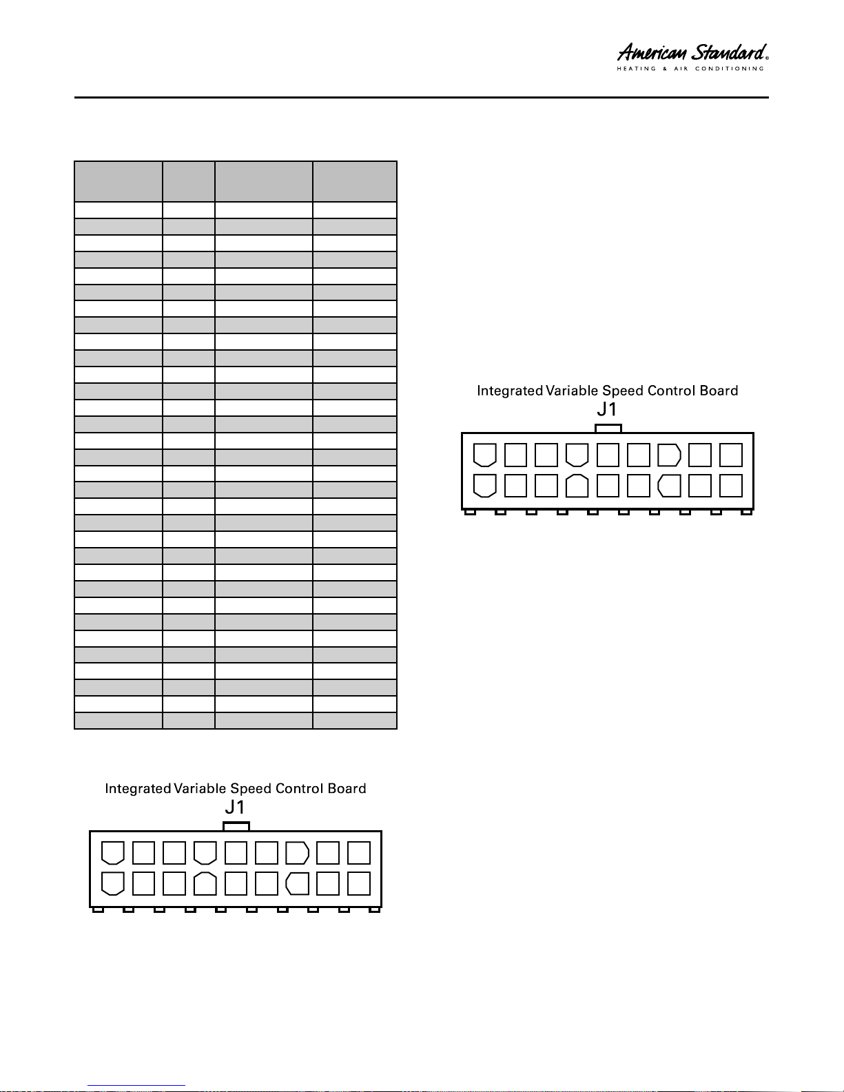
SSEENNSSOORRSS
Coil and Suction Temperature
Sensor
THERMISTOR
TEMP F TEMP C
-15 -26.11 135976 2.71
-10 -23.33 115112 2.64
-5 -20.56 97745 2.56
0 -17.78 83247 2.48
5 -15.00 71108 2.38
10 -12.22 60916 2.29
15 -9.44 52334 2.19
20 -6.67 45088 2.08
25 -3.89 38952 1.97
30 -1.11 33742 1.86
35 1.67 29307 1.75
40 4.44 25520 1.64
45 7.22 22280 1.53
50 10.00 19499 1.42
55 12.78 17108 1.32
60 15.56 15045 1.22
65 18.33 13262 1.13
70 21.11 11717 1.04
75 23.89 10375 0.96
80 26.67 9207 0.88
85 29.44 8188 0.81
90 32.22 7297 0.74
95 35.00 6516 0.68
100 37.78 5830 0.62
105 40.56 5227 0.57
110 43.33 4695 0.52
115 46.11 4224 0.47
120 48.89 3808 0.43
125 51.67 3439 0.40
130 54.44 3111 0.36
135 57.22 2820 0.33
140 60.00 2559 0.30
RESISTANCE
(OHMS)
VOLTS DC
The Coil Temperature Sensor control has an NTC
thermistor input for sensing the coil temperature. This
reading is used by the defrost algorithm on heat pump
units. The thermistor has a nominal resistance of 10k
ohms at 75°F. The minimum range and resolutions as
measured across pins 2 and 11 required for Coil
Temperature Sensor is —50°F to 150°F
A working Coil Temperature Sensor is required for the
following:
• Defrost Initiation and Termination
• Compressor Sump Heat (Preheating)
• Diagnostics; Charge Level, Indoor/Outdoor Airflow
Figure 9. Suction Temperature Sensor
Pins 3 & 12 (Orange)
The Suction Temperature Sensor control utilizes an
NTC thermistor input for sensing the suction/gas
temperature. The thermistor has a nominal resistance
of ≈ 10k ohms at 75°F. The minimum range and
resolutions as measured across pins 3 and 12 required
for the Suction Temperature Sensor is —50°F to 150°F
A working Suction Temperature Sensor is required for:
• Outdoor EEV Control (Target Super Heat)
• Diagnostics; Charge level, Indoor/Oudoor Airflow
Figure 8. Coil Temperature Sensor
Pins 2 & 11 (Yellow)
4A-V0-SF-1G-EN
19
123456789
101112131415161718
SSEENNSSOORRSS
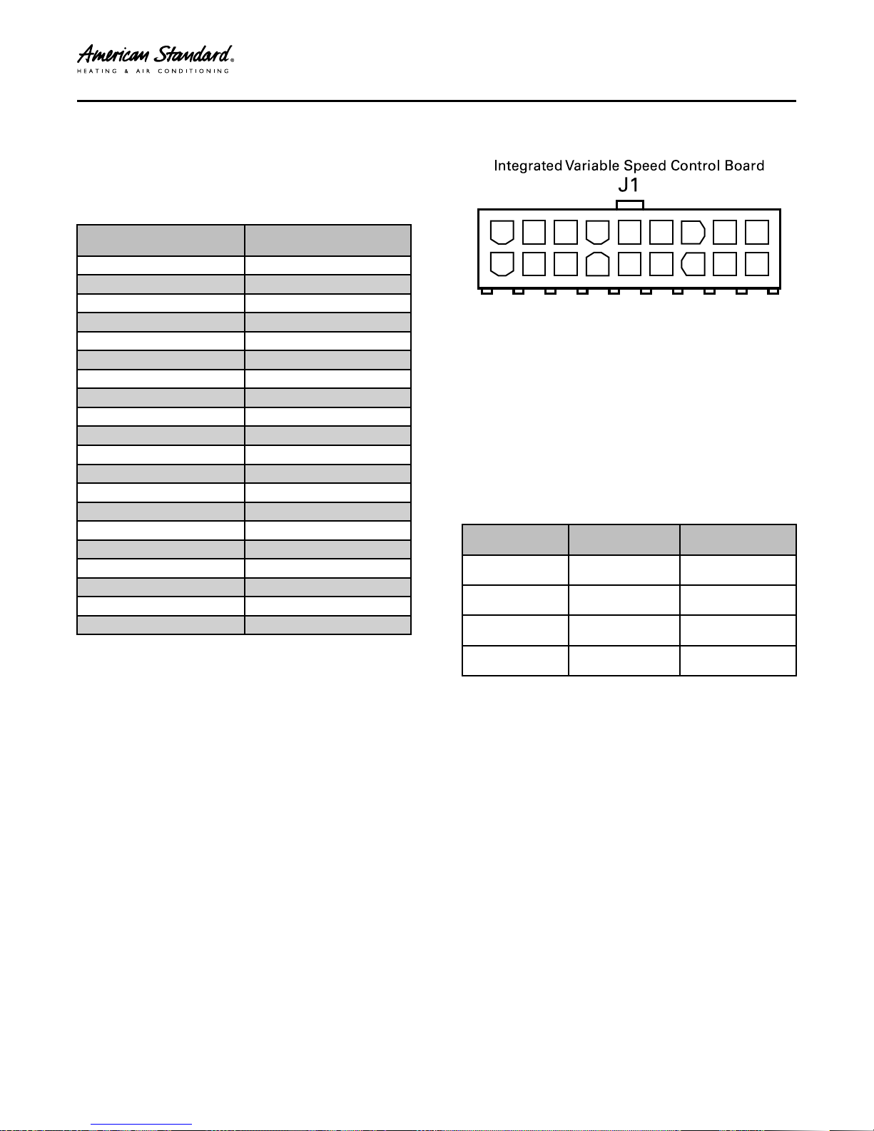
Suction Line Pressure
Transducer
This table shows the corresponding voltage and
pressure readings for the Suction Line Pressure
Transducer when measured across pins 7 and 8.
PRESSURE (PSIG)
10 0.60
20 0.70
31 0.81
41 0.91
51 1.00
60 1.10
70 1.20
82 1.32
92 1.42
101 1.52
111 1.62
120 1.72
130 1.81
140 1.91
152 2.03
161 2.13
171 2.23
181 2.33
190 2.43
200 2.52
VOLTS DC
PIN 7 TO PIN 8
Figure 10. Suction Pressure Transducer
Pins 7 (White) & 8 (Black)
A working Suction Pressure Sensor is required for the
following:
• Start Up (Pressure Limits)
• Low Pressure, Loss of Charge Protection
• Indoor Coil Freeze Protection
• Outdoor EEV Control (Target Super Heat)
• Diagnostics; Reverse Rotation, Charge Level,
Indoor/Outdoor Airflow
The Suction Pressure Transducer control is measured
across pins 7 and 8 and has an active 0–4.9VDC
transducer input for sensing low suction pressure.
DESCRIPTION LOCATION WIRE COLOR
4.9 VDC POWER PIN 6 RED
OUTPUT PIN 7 WHITE
COMMON PIN 8 BLACK
GROUND PIN 9 GREEN
20
4A-V0-SF-1G-EN
Variable Speed Alert Codes
Alert
Code
18
67
68
Alert
Group
Control
Failure
Temp
Sensor
Fault
Defrost
Fault
Display
Assembly
Text
CTRL FLT 4 Err 18.04
AMB T SENSE 0 Err 67.00
COIL T SENSE 1 Err 67.01
EXT T SENSE 3 Err 67.03
DOME T SENSE 4 Err 67.04
DOME T SENSE 5 Err 67.05
SUCT T SENSE 6 Err 67.06
SUCT T SENSE 7 Err 67.07
CDT UNATCHD 8 Err 67.08 Heating - Limp along
DFT FAULT A 0
DFT FAULT B/C
DFT FAULT
A(B/C)
Subalar-
m
1
2
A/TZONE
850/950
N/A
N/A
N/A
State action on
occurrence
Shutdown. Send Err
code to thermostat
and Fault text to CDA
For Cooling mode,
“Assume Ambient
Temp” as per Limp
along mode and
Continue normal
operation. For Heating
mode, go to timed
defrost.
For Cooling mode,
continue normal
operation. For heating
mode, go to timed
defrost.
Cooling - Normal
operation
Cooling - Normal
operation
Heating - Limp along
mode of constant
speed (compressor
speed is limited to
2400 RPM)
Cooling - Normal
operation
Heating - Limp along
mode of constant
speed (Compressor
speed is limited to
2400 RPM, EEV is
locked to safe position)
mode of constant
speed (compressor
speed is limited to
2400 RPM)
As defined in Defrost
algorithm
As defined in Defrost
algorithm
As defined in Defrost
algorithm
State action on
clearance
Resume normal
operation.
With actual
ambient
temperature,
continue normal
operation. For
Heating mode,
follow demand
defrost algorithm
For Cooling mode,
continue normal
operation. For
heating mode, go
to timed defrost.
Continue normal
operation
Continue normal
operation
Ramp up to
demand speed and
resume normal
operation.
Continue normal
operation
Ramp up to
demand speed and
resume normal
operation.
Ramp up to
demand speed and
resume normal
operation.
Continue normal
operation
Continue normal
operation
Continue normal
operation
Alert
Description
Internal control
error is detected
Ambient
Temperature
Sensor alert
Coil Temperature
Sensor alert
External
Temperature
Sensor alert
Dome
Temperature
Sensor is faulted
in Cooling mode
Dome
Temperature
Sensor is faulted
in Heating mode
Suction
Temperature
Sensor is faulted
in Cooling mode
Suction
Temperature
Sensor is faulted
in Heating mode
Compressor
DomeTemperature Sensor not
attached to
Compressor
(Heating Mode)
Defrost Fault A
has been
detected
Defrost Fault B or
C has been
detected
Defrost Fault A
and B or A and C
have been
detected
Possible Cause
Control failure,
replace IVSC
Ambient Sensor outof-range (Open/
Shorted/Missing)
Coil Sensor out-ofrange (Open/
Shorted/Missing)
Ext Sensor out-of
range (Shorted)
Open/ Missing revert
to Ambient Sensor
input
Dome Sensor out-ofrange (Open/
Shorted/Missing)
Dome Sensor out-ofrange (Open/
Shorted/Missing)
Suction Sensor outof-range (Open/
Shorted/Missing)
Suction Sensor outof-range (Open/
Shorted/Missing)
Compressor
DomeTemperature
Sensor not attached
to Compressor
(Heating Mode)
Introduced with
AOCSoftware Version
2, Fall of 2014)
Low heat pump
capacity (Inoperative
compressor, loss of
charge, shorted coil
sensor, open ambient
sensor)
Fault B indicates 10
defrosts terminated
on time override.
Fault C indicates
sensor High Delta T.
Within a given length
of time, both faults
existed
4A-V0-SF-1G-EN
21
VVaarriiaabbllee SSppeeeedd AAlleerrtt CCooddeess
Alert
Code
80
80
88
90
91
106
Alert
Group
High
Pressure
Monitor
Fault
High
Pressure
Monitor
Fault
Ground
fault
Communi-
cation
Busy Fault
Communi-
cation
Fault
External
Shutdown
Fault
Display
Assembly
Text
HP SHORT LO 0 “Wait”
HP HARD LO 1 Err 80.01
HP RED RPS 2 “Wait”
GND FAULT LO 1 Err 88.01
SYS COM BUSY 2 Err 90.02
SYS COM ERR 2 Err 91.02
NO SYS CLK 3 Err 91.03 Shutdown
EXT SW OPEN 1 “Load Shed”
Subalar-
m
A/TZONE
850/950
State action on
5 min of compressor
lockout and send
“WAIT ”to thermostat
Lockout compressor
operation until power
cycle, No system
operation
On restart, after short
lockout, compressor
will operate at reduced
capacity and this alert
is declared. (Message
on Tstat informing of
reduced capacity)
Note: Recover reduced
capacity with each 2 hr
run time window
without an HPCO trip.
Emergency shutdown.
Drive will protect itself.
CLII bus must go idle.
Continue to operate
normally
Shutdown if Heat/Cool
demand message not
received for 3
reporting intervals.
Compressor cooling
operation shall not be
allowed.
occurrence
State action on
clearance
Restart with
reduced capacity.
(Capacity reduced
by 1/5 with each
occurrence)
Can be cleared only
on power cycle.
After power cycle,
the compressor
shall resume
normal operation.
Normal operation
resumes.
Can be cleared only
on power cycle.
After power cycle,
the compressor
shall resume
normal operation.
Resume normal
operation
Resume normal
operation
Resume normal
operation
Resume normal
operation. Cooling
operation allowed.
Alert
Description
High pressure
switch has
tripped resulting
in a High Pressure
Short Lock Out.
(HPCO limit =
650psig)
6 High Pressure
Short Lock Out
events have
occurred
resulting in a High
Pressure Hard
Lock Out. (High
Pressure Limit =
650psig)
High Pressure trip
point has been
exceeded and a 5
minute time out
has been
enforced. Restart
is allowed but
with reduced
capacity.
Grounding issue
from output of
the drive. If the
sum of all three
currents exceeds
10 amp to
ground
Communication
busy
Loss of Heat/Cool
demand message
Loss of Bit Master
External
shutdown switch
is Active and
input at T3 to T4
is open
Possible Cause
Overcharged.
Cooling Mode:
Outdoor Fan Failure,
clogged coil,
recirculation,
excessive high
ambient, non
condensable.
Heating Mode:
Indoor Fan Failure,
clogged coil, non
condensable.
Overcharged.
Cooling Mode:
Outdoor Fan Failure,
clogged coil,
recirculation,
excessive high
ambient, non
condensable. Heating
Mode: Indoor Fan
Failure, clogged coil,
non condensable.
Overcharged.
Cooling Mode:
Outdoor Fan Failure,
clogged coil,
recirculation,
excessive high
ambient, non
condensable.
Heating Mode:
Indoor Fan Failure,
clogged coil, non
condensable.
Burnt winding, faulty
current sensor,
internal board short,
pinched compressor
lead (shorted). Run
Drive Test.
(GoTo “Compressor
Verification”
troubleshooting flow
chart)
R & B to thermostat
reversed polarity
Open/Shorted Data
line Check for
reversed polarity
Bit Master Control
Fault
External Load Shed
device is active with
external switch
configured to Active
and input at T3 to T4
is open
22
4A-V0-SF-1G-EN
 Loading...