

American Standard 4A7V8048A1000A, 4A6V8049A1000A, 4A6V8048A1000A, 4A6V8037A1000A, 4A6V8036A1000A Installer's Manual
...
Scan to see help
videos on this
product
Installer’s Guide
Variable Speed AccuLink™™ System
Heat Pumps and Air Conditioners
4A6V8024A1000A
4A6V8036A1000A
4A6V8037A1000A
4A6V8048A1000A
4A6V8049A1000A
4A6V8060A1000A
4A7V8024A1000A
4A7V8036A1000A
4A7V8037A1000A
4A7V8048A1000A
4A7V8060A1000A
NNoottee:: “Graphics in this document are for representation
only. Actual model may differ in appearance.”
Only qualified personnel should install and service the equipment. The installation, starting up, and servicing of heating, ventilating, and
air-conditioning equipment can be hazardous and requires specific knowledge and training. Improperly installed, adjusted or altered
equipment by an unqualified person could result in death or serious injury. When working on the equipment, observe all precautions in the
literature and on the tags, stickers, and labels that are attached to the equipment.
October 2014
SSAAFFEETTYY WWAARRNNIINNGG
11-BC37D1-1D-EN
SAFETY SECTION — OUTDOOR
IImmppoorrttaanntt — This document contains a wiring diagram
and service information. This is customer property and
is to remain with this unit. Please return to service
information pack upon completion of work.
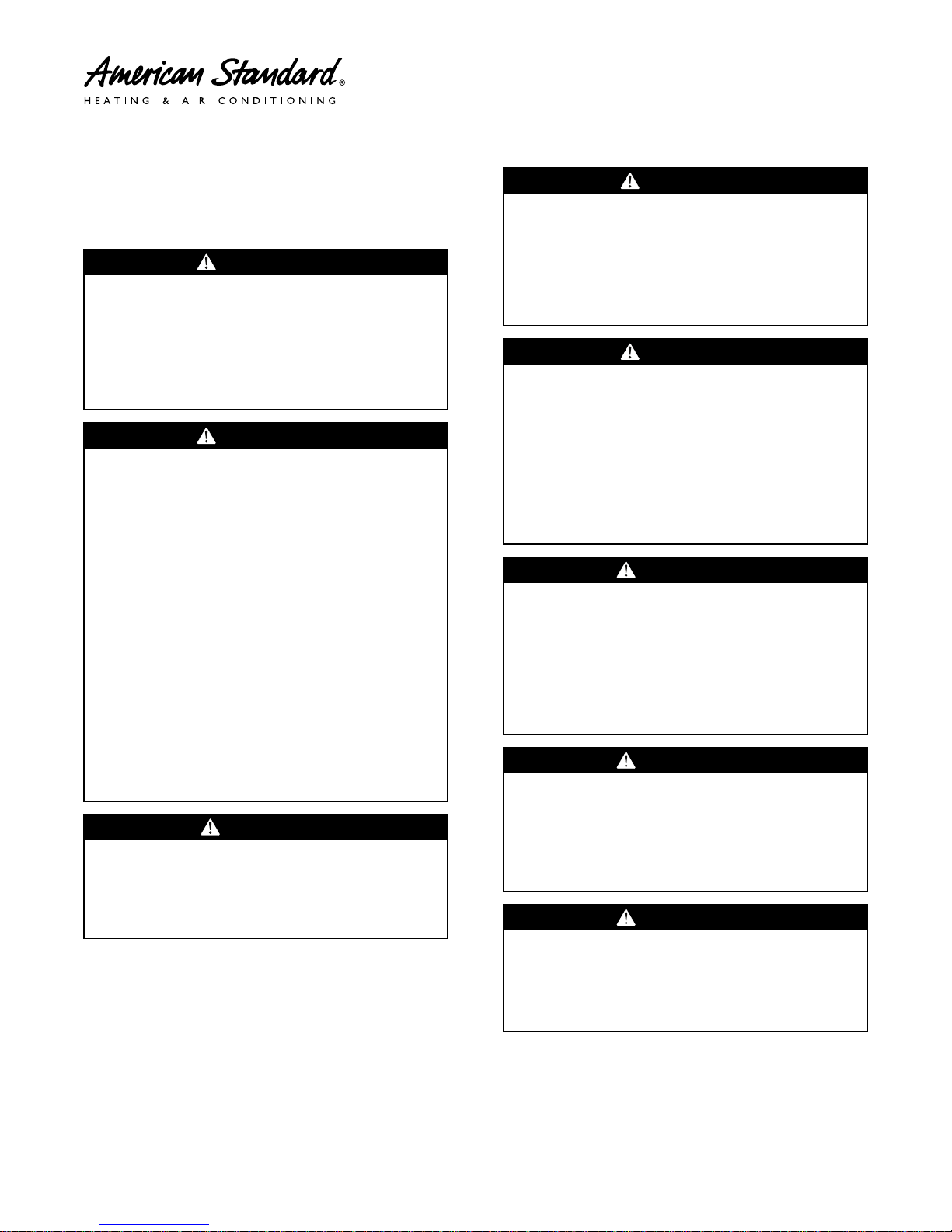
WWAARRNNIINNGG
HHAAZZAARRDDOOUUSS VVOOLLTTAAGGEE!!
FFaaiilluurree ttoo ffoollllooww tthhiiss WWaarrnniinngg ccoouulldd rreessuulltt iinn
pprrooppeerrttyy ddaammaaggee,, sseevveerree ppeerrssoonnaall iinnjjuurryy,, oorr ddeeaatthh..
DDiissccoonnnneecctt aallll eelleeccttrriicc ppoowweerr,, iinncclluuddiinngg rreemmoottee
ddiissccoonnnneeccttss bbeeffoorree sseerrvviicciinngg.. FFoollllooww pprrooppeerr
lloocckkoouutt//ttaaggoouutt pprroocceedduurreess ttoo eennssuurree tthhee ppoowweerr
ccaannnnoott bbee iinnaaddvveerrtteennttllyy eenneerrggiizzeedd..
WWAARRNNIINNGG
RREEFFRRIIGGEERRAANNTT OOIILL!!
AAnnyy aatttteemmpptt ttoo rreeppaaiirr aa cceennttrraall aaiirr ccoonnddiittiioonniinngg
pprroodduucctt mmaayy rreessuulltt iinn pprrooppeerrttyy ddaammaaggee,, sseevveerree
ppeerrssoonnaall iinnjjuurryy,, oorr ddeeaatthh..
TThheessee uunniittss uussee RR--441100AA rreeffrriiggeerraanntt wwhhiicchh ooppeerraatteess
aatt 5500 ttoo 7700%% hhiigghheerr pprreessssuurreess tthhaann RR--2222.. UUssee oonnllyy
RR--441100AA aapppprroovveedd sseerrvviiccee eeqquuiippmmeenntt.. RReeffrriiggeerraanntt
ccyylliinnddeerrss aarree ppaaiinntteedd aa ““RRoossee”” ccoolloorr ttoo iinnddiiccaattee
tthhee ttyyppee ooff rreeffrriiggeerraanntt aanndd mmaayy ccoonnttaaiinn aa ““ddiipp””
ttuubbee ttoo aallllooww ffoorr cchhaarrggiinngg ooff lliiqquuiidd rreeffrriiggeerraanntt iinnttoo
tthhee ssyysstteemm.. AAllll RR--441100AA ssyysstteemmss wwiitthh vvaarriiaabbllee
ssppeeeedd ccoommpprreessssoorrss uussee aa PPVVEE ooiill tthhaatt rreeaaddiillyy
aabbssoorrbbss mmooiissttuurree ffrroomm tthhee aattmmoosspphheerree.. TToo lliimmiitt
tthhiiss ““hhyyggrroossccooppiicc”” aaccttiioonn,, tthhee ssyysstteemm sshhoouulldd
rreemmaaiinn sseeaalleedd wwhheenneevveerr ppoossssiibbllee.. IIff aa ssyysstteemm hhaass
bbeeeenn ooppeenn ttoo tthhee aattmmoosspphheerree ffoorr mmoorree tthhaann 44
hhoouurrss,, tthhee ccoommpprreessssoorr ooiill mmuusstt bbee rreeppllaacceedd.. NNeevveerr
bbrreeaakk aa vvaaccuuuumm wwiitthh aaiirr aanndd aallwwaayyss cchhaannggee tthhee
ddrriieerrss wwhheenn ooppeenniinngg tthhee ssyysstteemm ffoorr ccoommppoonneenntt
rreeppllaacceemmeenntt..
CCAAUUTTIIOONN
HHOOTT SSUURRFFAACCEE!!
MMaayy ccaauussee mmiinnoorr ttoo sseevveerree bbuurrnniinngg.. FFaaiilluurree ttoo
ffoollllooww tthhiiss CCaauuttiioonn ccoouulldd rreessuulltt iinn pprrooppeerrttyy
ddaammaaggee oorr ppeerrssoonnaall iinnjjuurryy..
DDoo nnoott ttoouucchh ttoopp ooff ccoommpprreessssoorr..
CCAAUUTTIIOONN
CCOONNTTAAIINNSS RREEFFRRIIGGEERRAANNTT!!
FFaaiilluurree ttoo ffoollllooww pprrooppeerr pprroocceedduurreess ccaann rreessuulltt iinn
ppeerrssoonnaall iillllnneessss oorr iinnjjuurryy oorr sseevveerree eeqquuiippmmeenntt
ddaammaaggee..
SSyysstteemm ccoonnttaaiinnss ooiill aanndd rreeffrriiggeerraanntt uunnddeerr hhiigghh
pprreessssuurree.. RReeccoovveerr rreeffrriiggeerraanntt ttoo rreelliieevvee pprreessssuurree
bbeeffoorree ooppeenniinngg ssyysstteemm..
CCAAUUTTIIOONN
GGRROOUUNNDDIINNGG RREEQQUUIIRREEDD!!
FFaaiilluurree ttoo iinnssppeecctt oorr uussee pprrooppeerr sseerrvviiccee ttoooollss mmaayy
rreessuulltt iinn eeqquuiippmmeenntt ddaammaaggee oorr ppeerrssoonnaall iinnjjuurryy..
RReeccoonnnneecctt aallll ggrroouunnddiinngg ddeevviicceess.. AAllll ppaarrttss ooff tthhiiss
pprroodduucctt tthhaatt aarree ccaappaabbllee ooff ccoonndduuccttiinngg eelleeccttrriiccaall
ccuurrrreenntt aarree ggrroouunnddeedd.. IIff ggrroouunnddiinngg wwiirreess,, ssccrreewwss,,
ssttrraappss,, cclliippss,, nnuuttss,, oorr wwaasshheerrss uusseedd ttoo ccoommpplleettee aa
ppaatthh ttoo ggrroouunndd aarree rreemmoovveedd ffoorr sseerrvviiccee,, tthheeyy mmuusstt
bbee rreettuurrnneedd ttoo tthheeiirr oorriiggiinnaall ppoossiittiioonn aanndd pprrooppeerrllyy
ffaasstteenneedd..
WWAARRNNIINNGG
SSEERRVVIICCEE VVAALLVVEESS!!
FFaaiilluurree ttoo ffoollllooww tthhiiss wwaarrnniinngg wwiillll rreessuulltt iinn aabbrruupptt
rreelleeaassee ooff ssyysstteemm cchhaarrggee aanndd mmaayy rreessuulltt iinn
ppeerrssoonnaall iinnjjuurryy aanndd//oorr pprrooppeerrttyy ddaammaaggee..
EExxttrreemmee ccaauuttiioonn sshhoouulldd bbee eexxeerrcciisseedd wwhheenn
ooppeenniinngg tthhee LLiiqquuiidd LLiinnee SSeerrvviiccee VVaallvvee.. TTuurrnn vvaallvvee
sstteemm ccoouunntteerrcclloocckkwwiissee oonnllyy uunnttiill tthhee sstteemm
ccoonnttaaccttss tthhee rroolllleedd eeddggee.. NNoo ttoorrqquuee iiss rreeqquuiirreedd..
WWAARRNNIINNGG
BBRRAAZZIINNGG RREEQQUUIIRREEDD!!
FFaaiilluurree ttoo iinnssppeecctt lliinneess oorr uussee pprrooppeerr sseerrvviiccee ttoooollss
mmaayy rreessuulltt iinn eeqquuiippmmeenntt ddaammaaggee oorr ppeerrssoonnaall
iinnjjuurryy..
iiff uussiinngg eexxiissttiinngg rreeffrriiggeerraanntt lliinneess mmaakkee cceerrttaaiinn tthhaatt
aallll jjooiinnttss aarree bbrraazzeedd,, nnoott ssoollddeerreedd..
WWAARRNNIINNGG
HHIIGGHH LLEEAAKKAAGGEE CCUURRRREENNTT!!
FFaaiilluurree ttoo ffoollllooww tthhiiss WWaarrnniinngg ccoouulldd rreessuulltt iinn
pprrooppeerrttyy ddaammaaggee,, sseevveerree ppeerrssoonnaall iinnjjuurryy,, oorr ddeeaatthh..
EEaarrtthh ccoonnnneeccttiioonn eesssseennttiiaall bbeeffoorree ccoonnnneeccttiinngg
eelleeccttrriiccaall ssuuppppllyy..
©2014 American Standard Heating & Air Conditioning
11-BC37D1-1D-EN
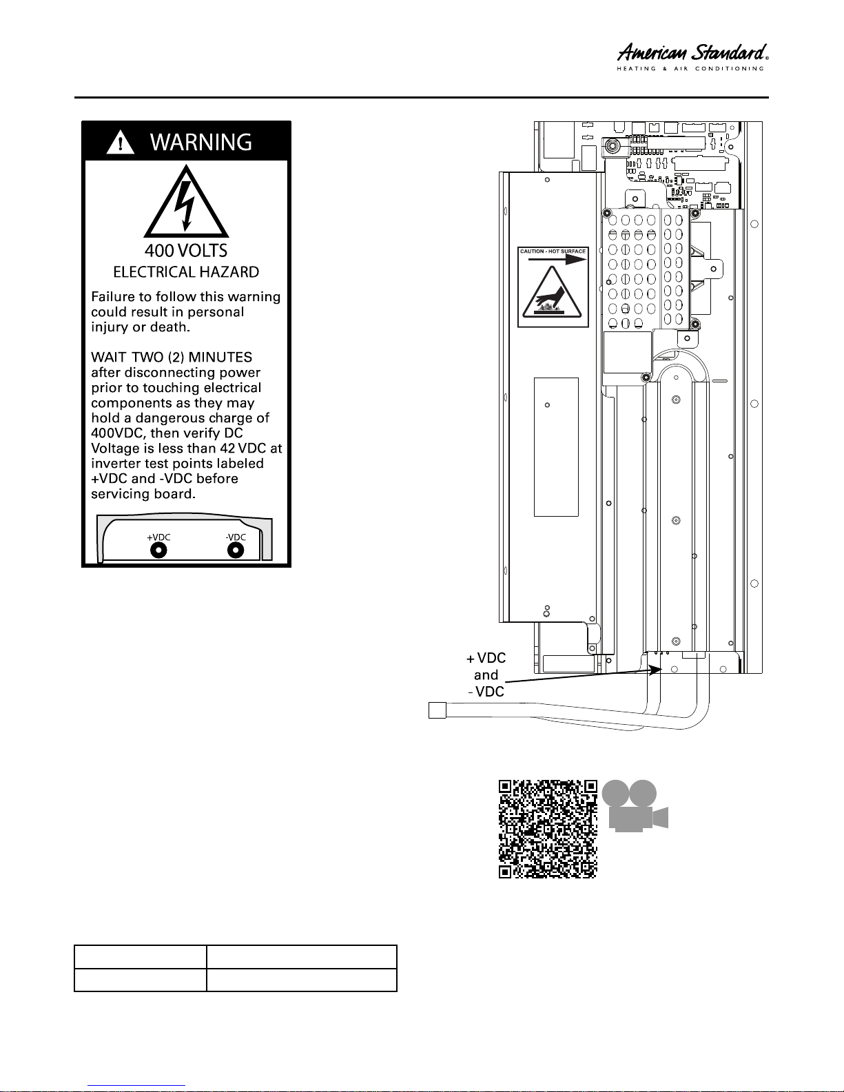
+VDC -VDC
ELECTRICAL HAZARD
Failure to follow this warning
coul d result in personal
injury or death.
WAIT TWO (2) MINUTES
after disconnecting power
prior to touching electrical
components as they may
hol d a dangerous charge of
400VDC, then verify DC
Voltage is less than 42 VDC at
inverter test points labeled
+VDC and -VDC befor e
ser vicing board.
400 VOLTS
WARNING
+ VDC
and
- VDC
CAUTION - HOT SURFACE
Scan to see an
overview video
about the IVSC
Board
SSAAFFEETTYY SSEECCTTIIOONN —— OOUUTTDDOOOORR
Approved Combinations for Variable Speed Units
• AZONE 850 Comfort Control, or AZONE 950 with Software Version
3.0 or Higher
• TAM8C or later models
• Platinum SV Furnace
• Platinum ZV Furnace
• Approved System Accessories
Note: See AHRI directory for approved indoor and outdoor model
combinations. Only Trane coils and air handlers are approved
for use with variable speed outdoor units.
Table 1. Operating Range
Cooling 55° F to 120° F
Heating -10° F to 66° F
11-BC37D1-1D-EN
3

Table of Contents
Unit Location Considerations. . . . . . . . . . . . . . . 5
. . . . . . . . . . . . . . . . . . . . . . . . . . . . . . . . . . . . . . . . . 6
Coastal Considerations . . . . . . . . . . . . . . . . 7
Unit Preparation. . . . . . . . . . . . . . . . . . . . . . . . . . . . 8
Setting Up the Unit . . . . . . . . . . . . . . . . . . . . . . . 8
Refrigerant Line Considerations . . . .. . . . . . . . 9
Refrigerant Line Brazing . . . . . . . . . . . . . . .. . . . 12
Refrigerant Line Leak Check . .. . . . . . . . . . . . . 14
Refrigerant Line and Indoor Coil
Evacuation . . . . . . . . . . . . . . . . . . . . . . . . . . . . . . 14
Charging: Weigh-In Method . . . . . . . .. . . . . . . 15
Service Valves . . . . . . . . . . . . . . . . .. . . . . . . . . .. . 16
Electrical — Low Voltage . . . . . . . . . . .. . . . . . . 17
Electrical — High Voltage . . . . . . . . . . . . . . . . . . 18
Integrated Variable Speed Control Board
LED Indicators . . . . . . . . . . .. . . . . . . . . . . . . . . . . . 19
Start Up . . . . . . . . . . . . . . . . . . . . . . .. . . . . . . . . . . . 20
System Charge Adjustment . . . . . . . . . . . . . . . 21
Subcool Charging Correction Charts. . . . . . . 22
Refrigerant Charging Chart . . . . . . . . . . . . . . . 22
Charging the Unit. . . . . . . . . . . . .. . . . . . . . . .. . . 23
Communicating Display Assembly
(CDA). . . . . . . . . . . . . . . . . . .. . . . . . . . . . . . . . . . . . . 25
Defrost Control (Heat Pump only). . . . . . . . . . 26
Checkout Procedures . . . . . . . . . . . . . . . .. . . . . . 27
4
11-BC37D1-1D-EN
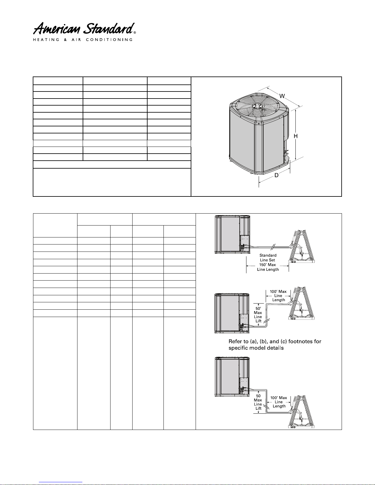
Unit Location Considerations
D
H
W
50’
Ma
x
Line
Lift
Sta n dard
Line Se t
150’ Max
Line Length
50
Max
Line
Lift
100’
M
ax
Line
Length
100’ Max
Line
Length
Refer to (a), (b), and (c) footnotes for
specific m odel details
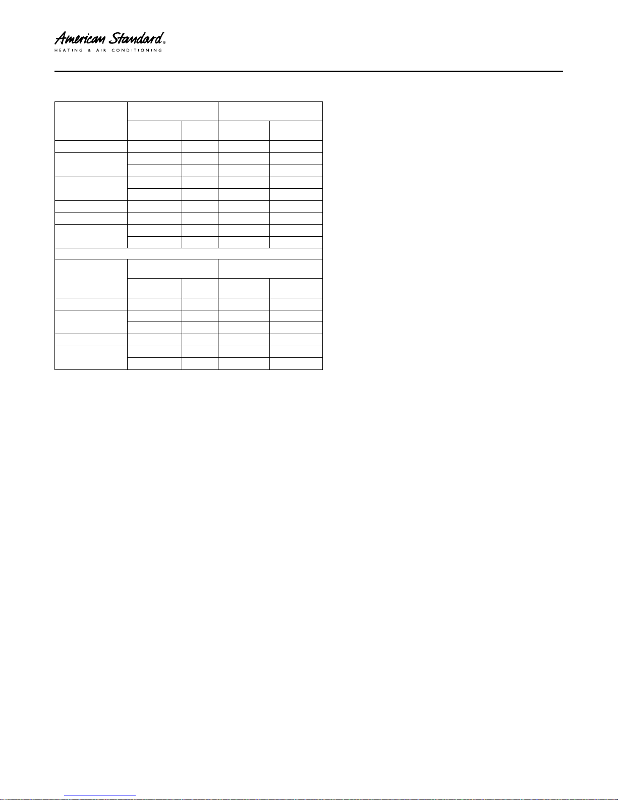
Table 2. Unit Dimensions and Weight
Models
4A6V8024A 41 x 30 x 33 195
4A6V8036A 41 x 30 x 33 208
4A6V8037A 41 x 34 x 37 229
4A6V8048A 41 x 34 x 37 234
4A6V8049A 41 x 34 x 37 241
4A6V8060A 45 x 34 x 37 250
4A7V8024A 41 x 30 x 33 196
4A7V8036A 41 x 30 x 33 207
4A7V8037A 41 x 34 x 37 225
4A7V8048A 41 x 34 x 37 245
4A7V8060A 45 x 34 x 37 250
* Weight values are estimated (uncrated).
• When mounting the outdoor unit on a roof, be sure the roof will
support the unit’s weight.
• Properly selected isolation is recommended to alleviate sound or
vibration transmission to the building structure.
Table 3. Refrigerant Line and Service Valve Connection Sizes
Model
4A6V8024A
4A6V8036A
4A6V8037A
4A6V8048A
4A6V8049A
4A6V8060A
4A7V8024A
4A7V8036A
4A7V8037A
4A7V8048A
4A7V8060A
H x D x W (in) Weight * (lb)
Rated Line Sizes
Vapor
Line
(a)
5/8
3/4 3/8 3/4 3/8
3/4 3/8 3/4 3/8
7/8 3/8 7/8 3/8
7/8 3/8 7/8 3/8
1—1/8
5/8 3/8 5/8 3/8
3/4 3/8 3/4 3/8
3/4 3/8 3/4 3/8
7/8 3/8 7/8 3/8
1—1/8
Liquid
Line
3/8 5/8 3/8
(b)
(c)
3/8 7/8 3/8
3/8 7/8 3/8
Service Valve
Connection Sizes
Vapor Line
Connection
Liquid Line
Connection
(a)
The max length of refrigerant lines from outdoor to indoor unit MUST NOT exceed 150 feet. The max vertical change MUST NOTexceed 50 feet.
(b)
The max length of refrigerant lines from the outdoor to indoor unit MUST NOTexceed 80 feet. The max vertical change MUST NOT exceed 10 feet.
(c)
The max length of refrigerant lines from outdoor to indoor unit MUST NOT exceed 80 feet. The max vertical change MUST NOTexceed 25 feet.
11-BC37D1-1D-EN
5
UUnniitt LLooccaattiioonn CCoonnssiiddeerraattiioonnss
Table 4. Alternate Refrigerant Line and Service Valve Connection Sizes
Service Valve
Connection Sizes
Vapor Line
Connection
Liquid Line
Connection
Model
4A6V8024A
4A6V8036A
4A6V8037A
4A6V8048A
4A6V8049A
4A6V8060A
Alternate Line Sizes
Vapor
Line
(a)
3/4"
5/8"
7/8"
5/8"
7/8"
3/4"
3/4"
3/4"
7/8"
(a)
(b)
(a)
(b)
(a)
(a)
(a)
(a)
5/16" 5/8" 3/8"
5/16" 3/4" 3/8"
5/16" 3/4" 3/8"
5/16" 3/4" 3/8"
5/16" 3/4" 3/8"
3/8" 7/8" 3/8"
3/8" 7/8" 3/8"
3/8" 7/8" 3/8"
3/8" 7/8" 3/8"
Liquid
Line
Model
4A7V8024A
4A7V8036A
4A7V8048A
4A7V8060A
(a)
The max length of refrigerant lines from outdoor to indoor unit MUST NOT exceed 150 feet. The max vertical change MUST NOTexceed 50 feet.
(b)
The max length of refrigerant lines from outdoor to indoor unit MUST NOT exceed 80 feet. The max vertical change MUST NOTexceed 25 feet.
3/4"
5/8"
7/8"
3/4"
3/4"
7/8"
Vapor
Line
(a)
(a)
(b)
(a)
(a)
(a)
Liquid
Line
5/16" 5/8" 3/8"
5/16" 3/4" 3/8"
5/16" 3/4" 3/8"
3/8" 7/8" 3/8"
3/8" 7/8" 3/8"
3/8" 7/8" 3/8"
Alternate Line Sizes
Service Valve
Connection Sizes
Vapor Line
Connection
Liquid Line
Connection
6
11-BC37D1-1D-EN
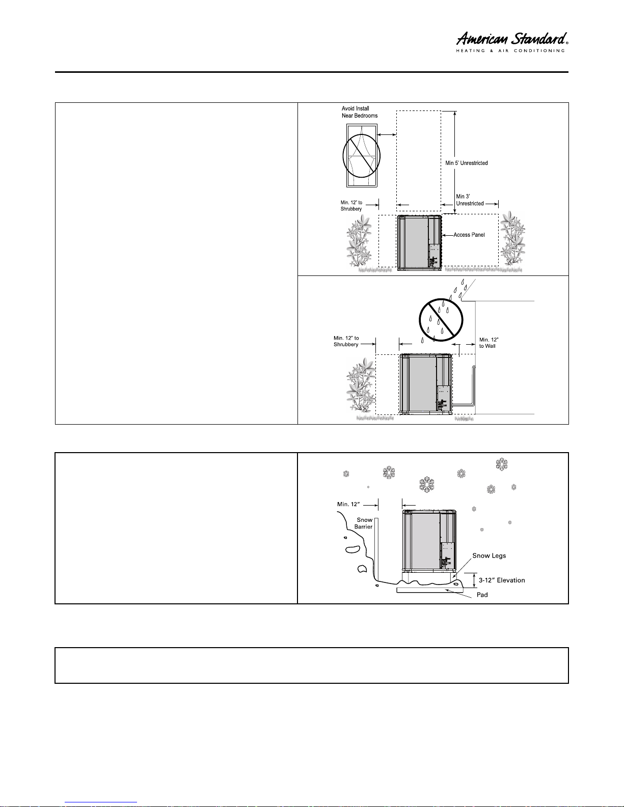
Table 5. Suggested Locations for Best Reliability
Min. 12” to
Shrubbe ry
Avoid Install
Nea r Bedrooms
Min 5’ Unre stricte d
Access Pa nel
Min 3’
Unrestricted
Min. 12” to
Shrubbery
Min. 12”
to Wall
Min. 12”
Sn ow
Barrier
3-12” Elevation
Snow L egs
Pad
• Ensure the top discharge area is unrestricted for at least 5
feet above the unit.
• Provide at least 3 feet clearance in front of the control box
(access panels) and any other side requiring service.
• Do not locate close to bedrooms as operational sounds may
be objectionable.
• Avoid locations near windows and similar areas where
condensation and freezing defrost vapor can annoy a
customer.
• Position the outdoor unit a minimum of 12” from any wall or
surrounding shrubbery to ensure adequate airflow.
• Outdoor unit location must be far enough away from any
structure to prevent excess roof runoff water or icicles from
falling directly on the unit.
• Position the outdoor unit a minimum of 12” from any wall or
surrounding shrubbery to ensure adequate airflow.
• Outdoor unit location must be far enough away from any
structure to prevent excess roof runoff water or icicles from
falling directly on the unit.
UUnniitt LLooccaattiioonn CCoonnssiiddeerraattiioonnss
Table 6. Cold Climate Considerations (Heat Pump Only)
Note: It is recommended that these precautions be taken for
units being installed in areas where snow accumulation and
prolonged below-freezing temperatures occur.
• Units should be elevated 3–12 inches above the pad or
rooftop, depending on local weather. This additional height
will allow drainage of snow and ice melted during defrost cycle
prior to its refreezing. Ensure that drain holes in unit base pan
are not obstructed, preventing drainage of defrost water.
• If possible, avoid locations that are likely to accumulate snow
drifts. If not possible, a snow drift barrier should be installed
around the unit to prevent a build-up of snow on the sides of
the unit.
Coastal Considerations
If installed within one mile of salt water, including seacoasts and inland waterways, models without factory supplied Seacoast Salt Shields
require the addition of BAYSEAC001 (Seacoast Kit) at installation time.
11-BC37D1-1D-EN
7
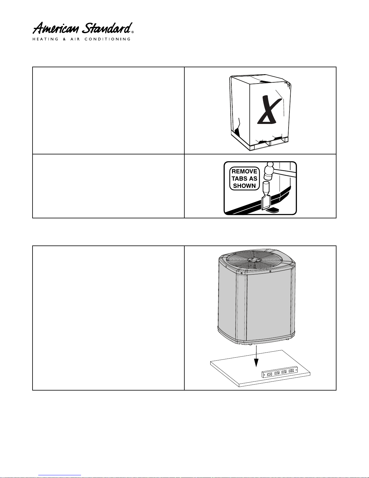
Unit Preparation
1. Check for damage and report promptly to the carrier
any damage found to the unit.
2. To remove the unit from the pallet, remove tabs by
cutting with a sharp tool.
Setting Up the Unit
Table 7. Pad Installation
When installing the unit on a support pad, such as a concrete slab,
consider the following:
• The pad should be at least 1” larger than the unit on all sides.
• The pad must be separate from any structure.
• The pad must be level.
• The pad should be high enough above grade to allow for drainage.
• The pad location must comply with National, State, and Local
codes.
8
11-BC37D1-1D-EN
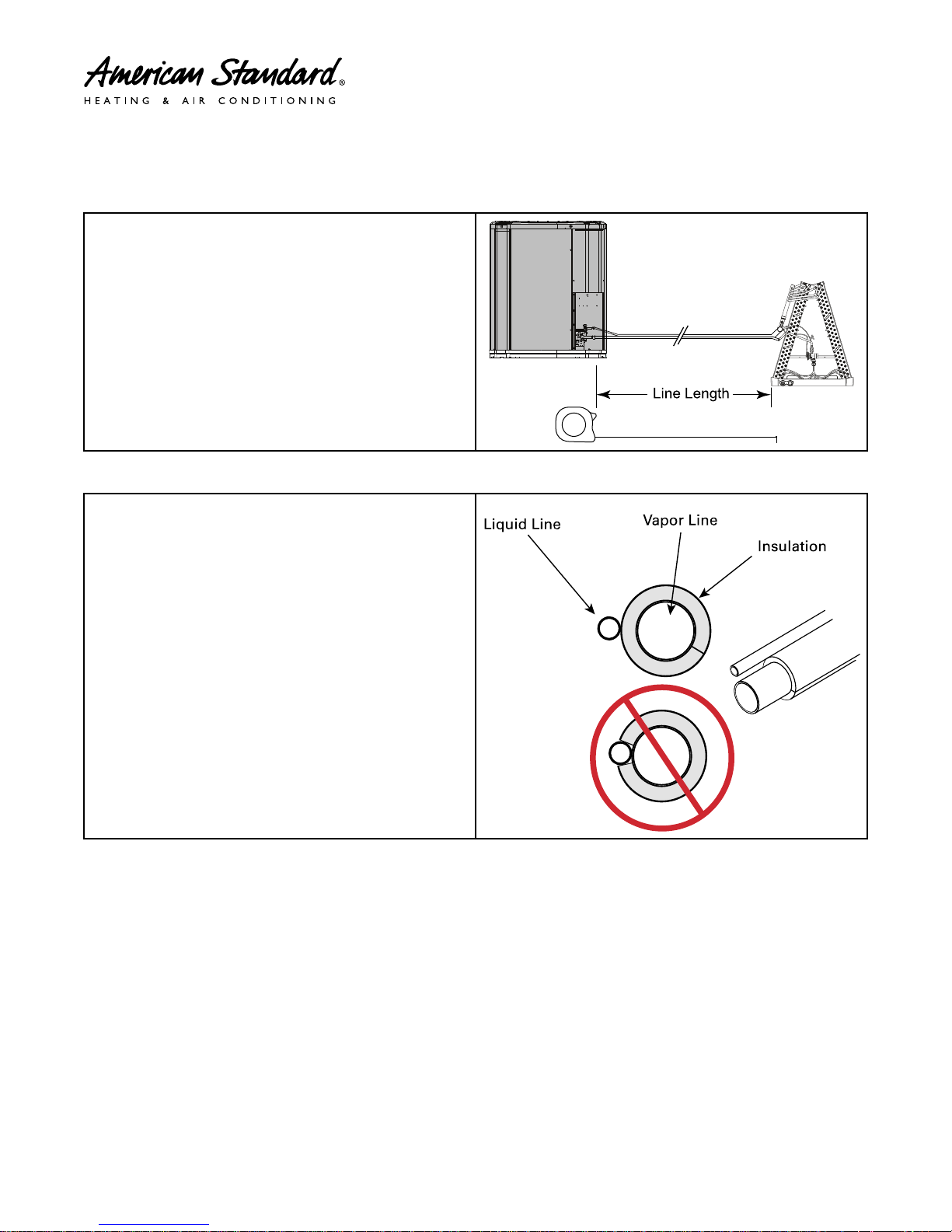
Refrigerant Line Considerations
Line Length
Liquid Li ne
Vapor Line
Insulati on
Table 8. Required Refrigerant Line Length
Determine required line length and lift. You will need this to determine
the subcooling charging corrections later in the installation process.
Total Line Length = ___________________________Ft.
Total Vertical Change (lift) = ____________________Ft.
Table 9. Refrigerant Line Insulation
Important: The Vapor Line must always be insulated. DO NOT allow
the Liquid Line and Vapor Line to come in direct (metal to
metal) contact.
Note: The gas line must always be insulated. Insulating the liquid line
through attic spaces may benefit system performance by
minimizing heat gain in the liquid line.
11-BC37D1-1D-EN
9
 Loading...