

American Standard 2A7A1048A, 2A7A1036A, 2A7A1030A, 2A7A1060A, 2A7A2024A Installer's Manual
...
11-AC11D2-5
INSTALLER'S GUIDE
ALL phases of this installation must comply with NATIONAL, STATE AND LOCAL CODES
Condensing Units
Models
IMPORTANT — This Document is customer property and is to remain with this unit. Please return to service information pack
upon completion of work.
:
2A7A5024-048, 2A7A4018-060,
2A7A2018-060 & 2A7A1018-060
These instructions do not cover all variations in systems
nor provide for every possible contingency to be met in
connection with installation. All phases of this installation must comply with NATIONAL, STATE AND LOCAL
CODES. Should further information be desired or should par-
ticular problems arise which are not covered sufficiently for the
purchaser’s purposes, the matter should be referred to your
installing dealer or local distributor.
A. GENERAL
The following instructions cover 2A7A5, 2A7A4, 2A7A2, & 2A7A1
Condensing Units.
NOTE: The 2A7A4, 2A7A2,& 2A7A1 outdoor units, except
for the 5 ton models, may be used with indoor units
equipped with Thermostatic Expansion Valve or Accutron™
Flow Control Check Valve (F.C.C.V.) assembly for refrigerant flow control only. The 2A7A5 & all 5 ton outdoor units
must be used with indoor units equipped with Thermostatic Expansion Valve only.
Check for transportation damage after unit is uncrated. Report
promptly, to the carrier, any damage found to the unit.
To determine the electrical power requirements of the unit, refer
to the nameplate of the unit. The electrical power available must
agree with that listed on the nameplate.
B. LOCATION & PREPARATION OF THE UNIT
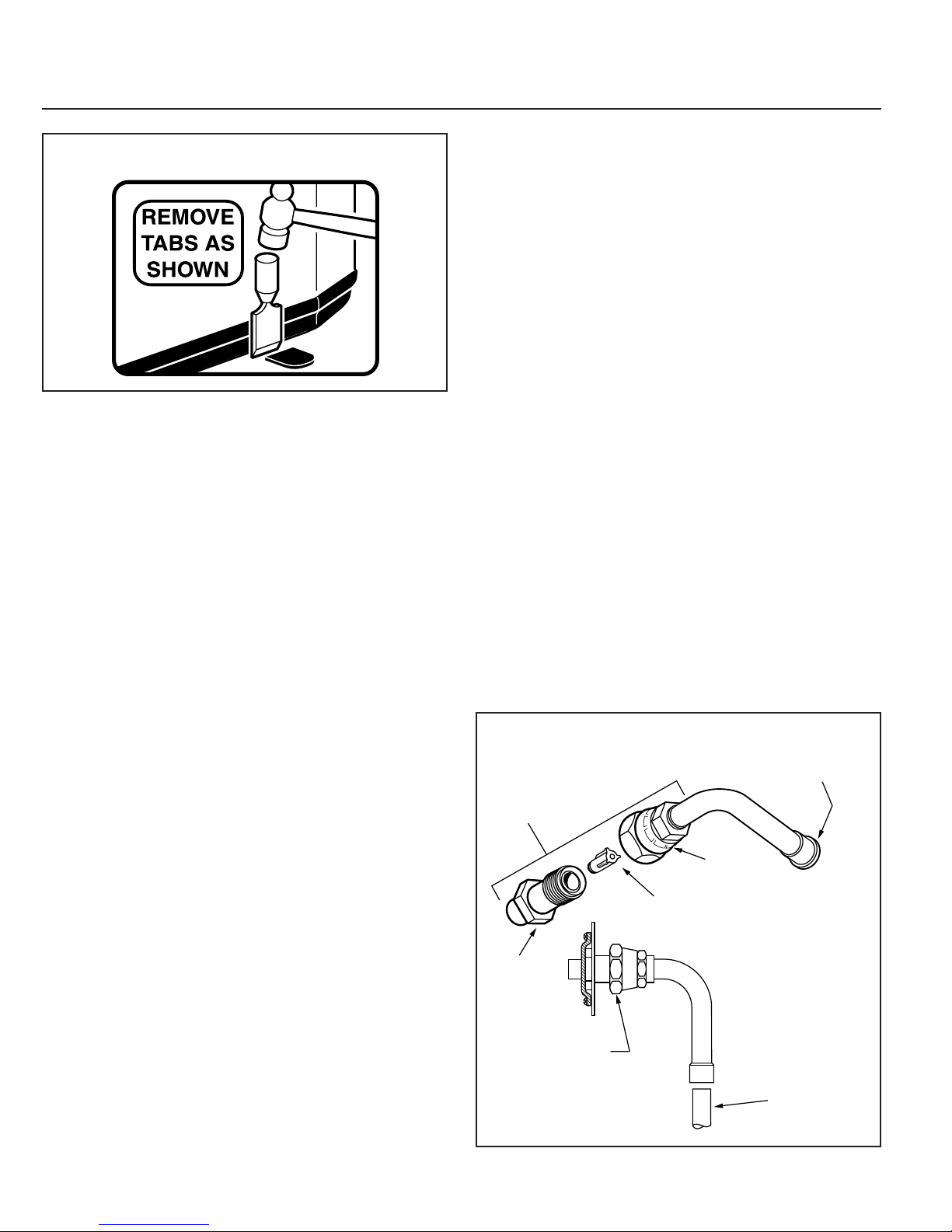
1. When removing unit from the pallet, notice the tabs on the
basepan. Remove tabs by cutting with a sharp tool as shown in
Figure 2 (see page 2).
2. The unit should be set on a level support pad at least as large
as the unit base pan, such as a concrete slab. If this is not the
application used please reference ALG-APG0*-EN (*latest revision number).
3. The support pad must NOT be in direct contact with any
structure. Unit must be positioned a minimum of 12" from any
wall or surrounding shrubbery to insure adequate airflow.
Clearance must be provided in front of control box (access
panels) & any other side requiring service access to meet
National Electrical Code. Also, the unit location must be far
enough away from any structure to prevent excess roof run-off
water from pouring directly on the unit. When choosing the
location of the unit(s), sound transmission through air and
© 2005 American Standard Inc. All Rights Reserved
TOP DISCHARGE — UNRESTRICTED
1
refrigerant lineset should be taken into consideration. It is
recommended to locate unit(s) away from areas (bedrooms, etc.)
where such sound could be objectionable.
4. The top discharge area must be unrestricted for at least
five (5) feet above the unit.
5. When the outdoor unit is mounted on a roof, be sure the roof
will support the unit’s weight. Properly selected isolation is
recommended to prevent transmission to the building structure.
6. The maximum length of refrigerant lines from outdoor to
indoor unit should NOT exceed sixty (60) feet.
7. If outdoor unit is mounted above the air handler, maximum
lift should not exceed sixty (60) feet (suction line). If air handler
is mounted above condensing unit, maximum lift should not
exceed sixty (60) feet (liquid line).
8. Locate and install indoor coil or air handler in accordance
with instruction included with that unit.
NOTE: Refer to “Refrigerant Piping Software” Pub. No.
32-3312-0*, and “Refrigerant Piping Manual” Pub. No.
32-3009-0* (the position of the * denotes latest revision
number).
5 FT. ABOVE UNIT
Since the manufacturer has a policy of continuous product
and product data improvement, it reserves the right to
change design and specifications without notice.
INSTALLER'S GUIDE
2
C. ACCUTRON™ FLOW CONTROL VALVE
If the indoor unit System Refrigerant Flow control is an
Accutron™ orifice and check valve assembly, an orifice size
change may be necessary. See Figure 3.
The outdoor model determines the required orifice size. Check
the listed orifice size on nameplate of the selected outdoor model.
If the indoor unit is factory shipped with a different orifice size,
the orifice must be changed to obtain system rated performance.
IMPORTANT: The outdoor unit is shipped with the proper size
orifice and a stick-on orifice size label in an envelope attached to
the outdoor unit. Outdoor unit nameplate will have correct
orifice size specified as BAYFCCV --- A for rated performance.
D. INSTALLING REFRIGERANT LINES
▲ CAUTION:
make certain that all joints are brazed, not soldered.
Condensing units have provisions for braze connections.
Pressure taps are provided on the service valves of outdoor unit
for compressor suction and liquid pressures.
The indoor end of the recommended refrigerant line sets may be
straight or with a 90 degree bend, depending upon situation
requirements. This should be thoroughly checked out before
ordering refrigerant line sets.
The gas line must always be insulated.
▲ CAUTION:
tions, dome temperatures may be hot. Do not touch top of
compressor, may cause minor to severe burning.
The units are factory charged with the system charge required
when using fifteen (15) feet of connecting line. Unit nameplate
charge is the same.
Final refrigerant charge adjustment is necessary. Use the
Charging Charts in the outdoor unit Service Facts.
1. Determine the most practical way to run the lines.
2. Consider types of bends to be made and space limitations.
NOTE: Large diameter tubing will be very difficult to rebend once
it has been shaped.
3. Determine the best starting point for routing the refrigerant
tubing — INSIDE OR OUTSIDE THE STRUCTURE.
BASEPAN TAB REMOVAL
If using existing refrigerant lines
In scroll compressor applica-
4. Provide a pull-thru hole of sufficient size to allow both liquid
and gas lines.
5. Be sure the tubing is of sufficient length.
6. Uncoil the tubing — do not kink or dent.
7. Route the tubing making all required bends and properly
secure the tubing before making connections.
8. To prevent a noise within the building structure due to
vibration transmission from the refrigerant lines, the following
precautions should be taken:
a. When the refrigerant lines have to be fastened to floor
joists or other framing in a structure, use isolation type hangers.
b. Isolation hangers should also be used when refrigerant
lines are run in stud spaces or enclosed ceilings.
c. Where the refrigerant lines run through a wall or sill, they
should be insulated and isolated.
d. Isolate the lines from all ductwork.
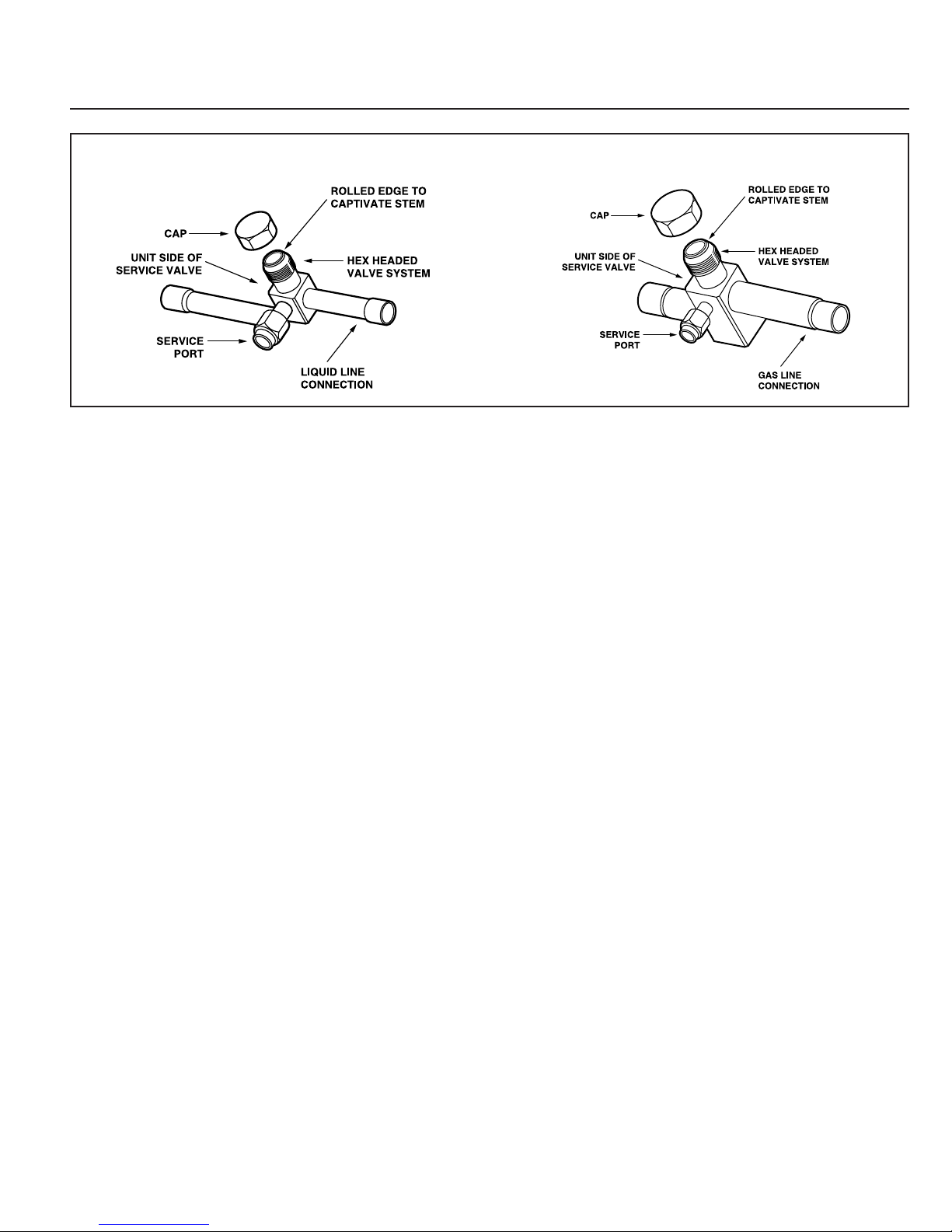
E. SERVICE VALVE OPERATION
BRASS LIQUID AND GAS LINE SERVICE VALVES
The Brass Liquid and Gas Line Service Valves are factory
shipped in the seated position to hold factory charge. The
pressure tap service port (when depressed) opens only to the field
brazing side of the valve when the valve is in the seated position.
The liquid line valve is not a back seating valve (see WARNING
that follows).
▲
WARNING:
ercised when opening the Liquid Line Service Valve.
Turn valve stem counterclockwise only until the stem
contacts the rolled edge. (See Figure 4) No torque is
required.
3
ACCUTRON
COMPONENTS
BODY
BRAZE TYPE INDOOR END
TM
AS SHIPPED
Extreme caution should be ex-
SEALING CAP
ADAPTER
FLOW CONTROL
CHECK VALVE
(F.C.C.V.) ORIFICE
FIELD SUPPLIED
LIQUID LINE
PAGE 2 Pub. No. 11-AC11D2-5
INSTALLER'S GUIDE
4
BRASS GAS LINE BALL SERVICE VALVE
The Brass Gas Line Ball Service Valve is shipped in the closed
position to hold the factory refrigerant charge. The pressure tap
service port (when depressed) opens only to the field brazing side
when the valve is in the closed position.
The Gas Line Ball Service Valve is full open with a 1/4 turn. See
Figure 5.
BRAZING REFRIGERANT LINES
1. Remove lower access cover to access service valves.
2. Before brazing, remove plugs from external copper stub
tubes. Clean internal and external surfaces of stub tubes prior
to brazing.
3. Cut and fit tubing, minimizing the use of sharp 90° bends.
4. Insulate the entire gas line and its fittings.
5. Do NOT allow uninsulated liquid line to come in direct
contact with bare gas line.
6. Precautions should be taken to avoid heat damage to
the pressure tap valve core during brazing. It is recommended that the pressure tap port valve core be removed
and a wet rag wrapped around the valve body.
NOTE: Use care to make sure that no moisture enters
pressure tap port, while wet rag is being used.
NOTE: Precautions should be taken to avoid heat damage
to basepan during brazing. It is recommended to keep the
flame directly off of the basepan.
7. Use a Dry Nitrogen Purge and Brazing Alloy without flux
when brazing the field line to the copper factory connection. Flow
dry nitrogen into either valve pressure tap port, thru the tubing
and out the other port while brazing.
8. Braze using accepted good brazing techniques.
LEAK CHECK
IMPORTANT: Replace pressure tap port valve core be-
fore attaching hoses for evacuation.
After the brazing operation of refrigerant lines to both the
outdoor and indoor unit is completed, the field brazed connections must be checked for leaks. Pressurize through the service
valve ports, the indoor unit and field refrigerant lines with dry
LIQUID LINE SERVICE VALVE
GAS LINE SERVICE VALVE
nitrogen to 350-400 psi. Use soap bubbles or other leak-checking
methods to see that all field joints are leak-free! If not, release
pressure; then repair!
SYSTEM EVACUATION
NOTE: Since the outdoor unit has a refrigerant charge, the gas
and liquid line valves must remain closed.
1. Upon completion of leak check, evacuate the refrigerant lines
and indoor coil before opening the gas and liquid line valves.
2. Attach appropriate hoses from manifold gauge to gas and
liquid line pressure taps.
NOTE: Unnecessary switching of hoses can be avoided and
complete evacuation of all lines leading to sealed system can be
accomplished with manifold center hose and connecting branch
hose to a cylinder of HCFC-22 and vacuum pump.
3. Attach center hose of manifold gauges to vacuum pump.
4. Evacuate until the micron gauge reads no higher than 350 microns.
5. Close off valve to vacuum pump and observe the micron
gauge. If gauge pressure rises above 500 microns in one (1)
minute, then evacuation is incomplete or system has a leak.
6. If vacuum gauge does not rise above 500 microns in one (1)
minute, the evacuation should be complete.
7. With vacuum pump and micron gauge blanked off, open valve
on R-410A cylinder and charge refrigerant lines and indoor coil
with vapor to tank pressure of HCFC-22 supply.
NOTE: DO NOT VENT REFRIGERANT INTO THE
ATMOSPHERE.
8. Close valve on HCFC-22 supply cylinder. Close valves on
manifold gauge set and remove refrigerant charging hoses from
liquid and gas pressure tap ports.
NOTE: A 3/16" Allen wrench is required to open liquid line
service valve. A 1/4" Open End or Adjustable wrench is required
to open gas line valve. A 3/4" Open End wrench is required to take
off the valve stem cap.
9. The liquid line shut-off valve can now be opened. Remove
shut-off valve cap. Fully insert hex wrench into the stem and
back out counterclockwise until valve stem just touches rolled
edge (approximately five (5) turns) observing WARNING statement on page 2. See Figure 4.
Pub. No. 11-AC11D2-5 PAGE 3
 Loading...