

Page 1
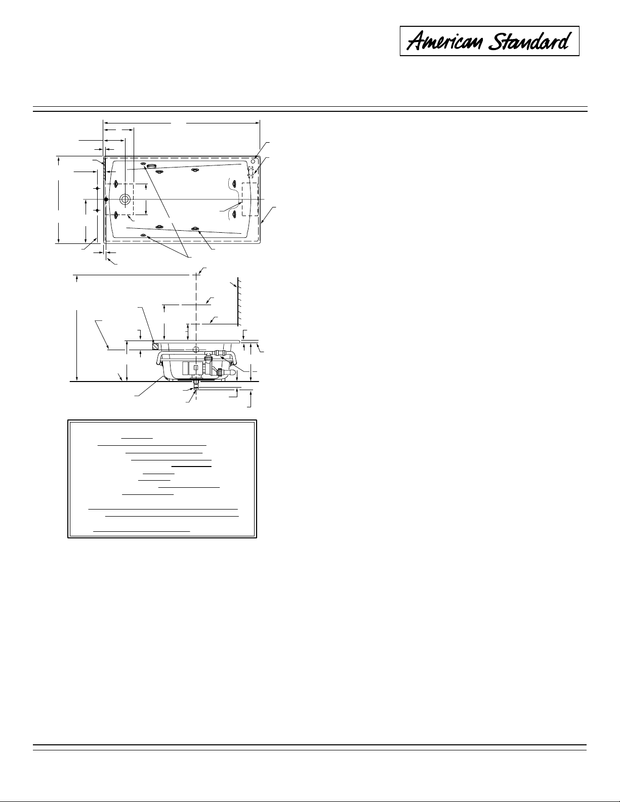
WILLIAMSBURG
2425E SERIES
ELITE 5' x 32"™
HIGH GLOSS ACRYLIC
SHOWN LESS ALL FITTINGS
12
10-1/4
(260mm)
FINISHED
SEE FITTING
SPECS FOR
DIMENSIONS
32
(813mm)
C/L OF
SUPPLIES
OPTIONAL TO
FINISHED FLOOR
USUALLY BETWEEN
65 & 78
(1651 & 1981mm)
(19mm)
WALL
(406mm)
INSTALLED SIZE
WEIGHT
WEIGHT w/WATER
GAL. TO OVERFLOW
WHIRLPOOL MIN. OPERATING VOL.
BATHING WELL AT SUMP
BATHING WELL AT RIM
WATER DEPTH TO OVERFLOW
FLOOR LOADING
(PROJECTED AREA)
PTS.
CUBE (FT
PUMP 1.6 HP, 9.7 AMPS,120V.
(305mm)
3/4
(229 mm)
16
C/L OF
OVERFLOW
ROUGH
FLOOR
GENERAL SPECIFICATIONS FOR 2425E WHIRLPOOL
3
)
WHIRLPOOL ELECTRICAL SPECIFICATIONS
CUTOUT IN FLOOR FOR DRAIN
3
(76mm)
C/L OF DRAIN
■ LEVELING
STRINGER
NOT FOR
SUPPORT
3-1/2
(89mm)
21-1/2
(546mm)
INTEGRAL
FEET
1-1/2 O.D.TAILPIECE
60
(1524mm)
9
PUMP
(8) JETS
(2) AIR VALVES
C/L OF
SHOWER ARM
FINISHED
WALL
C/L OF
VALVES
12
(305mm) OPT.
4
(102mm)
1-1/2 N.P.T.M.
THREADS
60 x 32 x 21-1/2 (1524 x 813 x 546mm)
16-1/4 x 38-1/4 (413 x 972mm)
26-1/4 x 52-1/2 (667 x 1334mm)
43 Lbs./Sq.Ft. (208 Kgs./Sq.m)
C/L OF
SPOUT
2-3/4
(70mm)
115 Lbs. (52 Kg.)
574 Lbs. (258 Kg.)
55 Gal. (208 L.)
45 Gal. (171 L.)
15 (381mm)
WHIRLPOOL
INSTALLATION INSTRUCTIONS
ON/OFF
4-5/8
(117mm)
19-1/2
(495mm)
20.8
35.3
2
(51mm)
SWITCH
HEATER
BLANK
PROVIDE ACCESS
TO PUMP FOR
SERVICE ON ALL
INSTALLATIONS
UNDERSIDE
OF DECK
IN-LINE HEATER
REMOVABLE
BLANK
THANK YOU...
for selecting an American Standard bath. Your new
bath is shipped to you after careful inspection. The
whirlpool version is completely assembled with pump,
motor, and system piping. All you need to finish the
installation are your selected fittings and electrical
connections for a whirlpool.
To insure maximum performance and pleasure from
this product, please follow the instructions and
cautions.
List of Optional Components (not included):
• Flex-Jet Pulse Jet Kit*
• Flex-Jet Soft Jet Kit*
• 5 Foot Apron*
• E-Z-Install Heater*
List of Required Components (not included):
• Drain* • Bath Filler*
* see your Home Depot Retailer
List of Required Tools and Supplies:
Tools
• Level
• Tape Measure
• Pipe Wrench
• Slip Joint Pliers
• Screw Driver
• Standard
Woodworking Tools
• Personal Safety
Equipment
• Caulking Gun
Supplies
• Nails
• Putty
• Caulking (waterproof)
• 1 x 3 or 2 x 2
Stringers
• Drop Cloth
• 15 amp GFI
Outlet
• Cement, Plaster,
Grout
GENERAL INSTALLATION INFORMATION
Carefully uncrate and inspect your new bath for any shipping damage. If such damage is found, report it to your vendor
immediately.
After inspection and during installation, protect the bath from construction damage. After installation, and before
enclosing with wallboard, tile, etc., water test the unit and check for leaks.
Do not make modifications to the whirlpool system or remove pump from factory mounting. This could adversely affect
the safety and performance of the whirlpool and void the warranty. Do not handle or move the whirlpool by the pump,
motor, or piping system.
Fittings (bath filler, shower arm, etc.) are not provided with the bath and must be ordered separately. Framing and
enclosing materials are provided by others. Check for availability of optional American Standard wall tiling bead
(required for recess installations).
Protect all finished surfaces of the whirlpool during construction and installation using a drop cloth.
WARNING! Do not lift whirlpool by the piping harness at any time.
FOR AFTER-SALES SERVICE CALL 1 (800) 442-1902 WEEKDAYS.
752875-100 Rev. D
© American Standard Inc. 2002
All product names listed herein are trademarks
of American Standard Inc. unless otherwise noted.
Page 2
INSTALLATION AND FRAMING INSTRUCTIONS
The variety of installations possible for this whirlpool may require framing procedures other than those shown. Locate studs
as required. Ensure roughing-in dimensions are proper, plumb and square. Provisions must be made in all installations for an
access opening for servicing the pump and controls. It is strongly recommended that an additional opening be provided for
access to the drain components.
NOTE: The apron should not be used as the primary access opening.
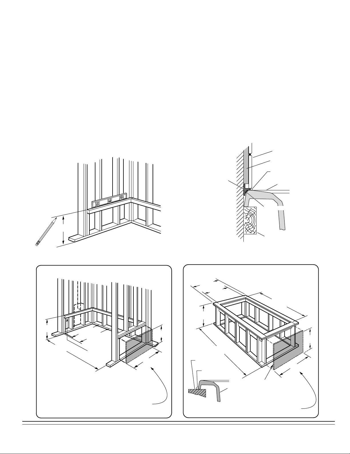
1. Position the whirlpool into the installation opening and level the deck, shimming the integral support feet as necessary.
Mark the final position of the underside of the deck by tracing a line on to the studs (see Figure 1).
2. Remove the whirlpool and attach a 1 x 3 stringer to the studs, with the top of the stringer touching the traced line.
3. Install drain components to the whirlpool following the manufacturers instructions. Before replacing your whirlpool for final
installation, be certain that an opening has been provided in the sub-floor for the drain. See the roughing-in drawing for
suggested opening size and location dimensions.
4. Replace whirlpool and re-shim the integral support feet, shimming the entire length of the support feet. Secure the shims
using construction adhesive, silicone, mortar or equivalent materials. While not a necessity, the use of a foundation base
consisting of cement (e.g. Sakrete), mortar, or grout will help provide a solid and secure installation.
FIG. 1
495mm
(19-1/2)
TYPICAL RECESS INSTALLATION
TILE
WALLBOARD
TILE
BEAD
STRIP
SEALANT
BATH
ADHESIVE
LEVELING
STRINGER
NOTE: Tile bead kit not included and must be
purchased separately.
TYPICAL PIER TYPE INSTALLATION
AS DESIRED
495mm
(19-1/2)
775mm
(30-1/2)
CUTOUT
1486mm
(58-1/2)
CUTOUT
495mm
(19-1/2)
1527mm
(60-1/8)
UNLESS AN ACCESS OPENING OF AT LEAST
12" X 24" (305 X 610MM) IS PROVIDED,
WARRANTY SERVICE WILL NOT BE PERFORMED.
752875-100 Rev. D
762mm
(30)
813mm
TUB WIDTH
LEVELING
STRINGERS
(32)
610 mm
(24)
305mm
(12)
(2)
AS
DESIRED
LEVELING
SURFACE
WATERPROOF
SEALANT
ACCESS PANEL
BATH
UNLESS AN ACCESS OPENING OF AT LEAST
12" X 24" (305 X 610MM) IS PROVIDED,
WARRANTY SERVICE WILL NOT BE PERFORMED.
610mm
(24)
305mm
(12)
Page 3
ELECTRICAL INSTALLATION INSTRUCTIONS
All wiring must be performed by a licensed electrician in accordance with the national electrical code and all other
applicable codes.
WARNING:
When using electrical products, basic precautions should always be observed, including the following:
1. DANGER: RISK OF ELECTRIC SHOCK
Connect only to a circuit protected by a ground-fault circuit interrupter.
2. Grounding is required. The unit should be installed by a licensed electrician and grounded.
3. Install to permit access for servicing.
4. All building materials and wiring should be routed away from the pump body and heater (if equipped).
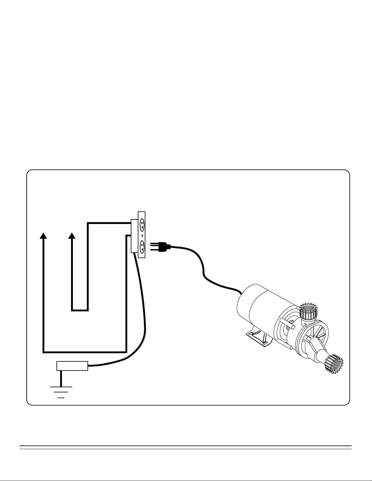
The whirlpool should be installed on a 120 vac, 15 amp dedicated circuit. The circuit should be hard-wired from the
electrical power supply panel. The circuit must be a three (3) wire circuit from the electrical supply panel. A grounded
neutral wire and a third wire, earth ground, are essential. ADDING THE E-Z-INSTALL HEATER REQUIRES A
SEPARATE 15 AMP MAXIMUM GFCI CIRCUIT.
ELECTRICAL INSTALLATION
SEPARATE
15 AMP GFCI
OUTLET
120 VAC
WHITE
GND.
WHIRLPOOL MOUNTED
AIR SWITCH OR
WALL TIMER
BLACK
PUMP/MOTOR
ELECTRICAL DIAGRAM
READ AND FOLLOW ALL INSTRUCTIONS
752875-100 Rev. D
(3)
Page 4

WIRE SELECTION GUIDE
Maximum distance from
fusebox to motor
The sizes shown on this
chart are recommendations
Motor
Hi Performance
Rating
1.6
DRAIN CONNECTION AND SYSTEM TEST
Using recommended drain opening, connect whirlpool drain to waste line. Tighten all drain joints securely. Check the
pump couplings and make sure they are hand-tight. Clean the whirlpool and fill with water to a point 2" above the top of
the highest jet. Recheck the pump couplings and make certain that they are not leaking. (Although the pump couplings
are factory tightened and inspected, some loosening may have occured during transit.) Make sure the whirlpool is
connected to the electrical supply and turn the whirlpool on. Check for leaks around all piping connections while the
whirlpool is running.
POST INSTALLATION CLEAN-UP
50' 100'
150' 200'
120V Power Line
12 12 10 8
for copper conductors
only. Always follow
local and national
electrical codes
Remove all construction debris from bath. Tile grout can be removed with a wooden popsicle stick or tongue depressor.
Do not use wire brushes or any other metal implement on bath surface.
Post installation clean-up generally can be completed using warm water and liquid dishwashing detergent. Stubborn dirt or
stains may be removed using granular Spic and Span® mixed with water.
Painter's naphtha can be used to remove excess adhesives and/or wet oil-base paint.
HARSH CHEMICALS SHOULD NEVER BE USED ON ACRYLIC SURFACES.
Abrasive cleaners must not be used since they will scratch and dull the surface. Dulled areas can be restored by rubbing
with a white automotive-type polishing compound and waxing with a liquid wax.
752875-100 Rev. D
(4)
SPIC AND SPAN® IS A REGISTERED TRADEMARK OF PROCTER & GAMBLE
 Loading...