

Page 1

THANK YOU...
for selecting an American Standard bath. Your new bath is shipped to you after careful inspection. The
whirlpool version is completely assembled with pump, motor, and system piping. All you need to finish the
whirlpool installation are your selected fittings and electrical connections.
To insure maximum performance and pleasure from this product, please follow the instructions and cautions.
CORNER DUET W/SEAT 60" x 60" MODEL 2351
CENTURION 6' x 36" MODEL 2371
CONTEMPO OVAL MODEL 2383
FREE SPIRIT 6' x 54" MODEL 2466
© AS Americas Inc. 010
All product names listed herein are trademarks
of AS Americas Inc. unless otherwise noted.
FOR AFTER-SALES SERVICE CALL 1 (00) 44-10 WEEKDAYS.
INSTALLATION GUIDE FOR
WHIRLPOOLS AND BATHTUBS
1
754407-100 Rev. B
Page 2

TABLE OF CONTENTS:
Safety Instructions............................................................................Page
General Information..........................................................................Page 4
Optional Components.......................................................................Page 4
Specifications....................................................................................Page 4
Roughing-in Reference.....................................................................Page 5
Framing and Support Instructions.....................................................Page
Mounting Instructions........................................................................Page 7
Electrical Connections.......................................................................Page
Drain Connection and System Test...................................................Page
Care and Cleaning.............................................................................Page
Warranty............................................................................................Page 10
754407-100 Rev. B
Page 3

!
!
!
!
!
!
!
SAVE THESE INSTRUCTIONS
WARNING:
Risk of personal injury.
Do not permit children to use this unit without adult supervision.
WARNING: Risk of personal injury. Do not operate this unit without the guard over the suction fitting.
WARNING:
Risk of electric shock. Do not permit electrical appliances (hair dryer, telephone, radio, etc.) within
0 inches (154mm) of this unit.
WARNING: Risk of hyperthermia and possible drowning. People using medications and/or having adverse
medical history should consult a physician before using this product.
WARNING: Risk of personal injury. Do not overfill unit before entering. Entering tub when filled more than /
can cause overflow and slippery conditions. Exercise caution when entering and exiting.
WARNING:
No Food or Alcoholic Beverages.
Use of your bathtub immediately after meals is not
recommended. Avoid alcohol consumption before or during bathing. Alcoholic beverages can cause drowsiness or
hyperthermia resulting in loss of consciousness or even drowning.
WARNING: Pregnancy. If you are or think you may be pregnant, consult your physician before using the bathtub.
Never drop or insert any object into any opening.
Use this unit only for its intended use as described in this manual. Do not use any attachments not recommended by
American Standard.
The unit must be connected only to a supply circuit that is properly protected by a ground-fault circuit-interrupter
(GFCI). Such a GFCI should be provided by the installer and should be tested on a routine basis. To test the GFCI,
push the test button. The GFCI should interrupt power. Push the reset button. Power should be restored. If the GFCI
fails to operate in this manner, the GFCI is defective. If the GFCI interrupts power to the bathtub without the test button
being pushed, a ground current is flowing, indicating the possibility of an electric shock. Do not use this hydromassage
bathtub. Disconnect the hydromassage bathtub and have the problem corrected by a licensed electrician before using.
A pressure wire connector is provided on the exterior of the motor unit to permit connection of a no. AWG solid
copper bonding conductor between this unit and all other electrical equipment and exposed metal in the vicinity, as
needed to comply with local requirements. To reduce the risk of an electric shock, connect this connector the
grounding terminal of your electric service or supply panel with a conductor equivalent in size to the circuit conductors
supplying this unit.
IMPORTANT SAFETY
INSTRUCTIONS
INSTRUCTIONS PERTAINING TO
A RISK OF FIRE, ELECTRIC SHOCK
OR INJURY TO PERSONS
READ AND FOLLOW ALL INSTRUCTIONS!
754407-100 Rev. B
Page 4
CORNER DUET WITH SEAT
CENTURION ' X "
CONTEMPO OVAL
FREE SPIRIT ' X 54"
51
71
4
EZHEAT-100
EZHEAT-100
EZHEAT-100
EZHEAT-100
N/A
N/A
N/A
N/A
751755-100
751755-100
N/A
751755-100
OPTIONAL COMPONENTS (NOT INCLUDED)
E-Z INSTALL HEATER APRON KIT TILE BEAD KIT
List of Required Tools and Supplies:
Tools
• Level
• Tape Measure
• Pipe Wrench
• Slip Joint Pliers
• Screw Driver
• Standard Woodworking Tools
• Personal Safety Equipment
• Caulking Gun
Supplies
• Nails
• Putty
• Caulking (waterproof)
• 1 x 4 Stringers
• Drop Cloth
• Cement, Plaster, Grout
General Installation Information
Carefully uncrate and inspect your new bath for any shipping damage. If such damage is found, report it to your vendor immediately. After
inspection and during installation, protect the bath from construction damage. Before installation, and before enclosing with wallboard,
tile, etc., the bath must be filled with water and operated to check for leaks that may have resulted from shipping damage or
mishandling! Do not make modifications to the whirlpool system or remove pump from factory mounting. This could adversely affect the
safety and performance of the whirlpool and void the warranty. Do not handle or move the whirlpool by the pump, motor, or piping system.
Fittings (bath filler, shower arm, etc.) are not provided with the bath and must be ordered separately. Framing and enclosing materials are
provided by others.
For electrical requirements, refer to section titled “Whirlpool Electrical Installation Instructions”.
Check for availability of optional American Standard wall tiling bead (required for recess installation).
Protect all finished surfaces of the whirlpool during construction and installation using a drop cloth.
DESCRIPTION
MODEL #
LIST OF OPTIONAL COMPONENTS (NOT INCLUDED):
• For these components please see your Vendor.
!
WARNING: Do not lift whirlpool by the piping harness at any time.
SPECIFICATIONS:
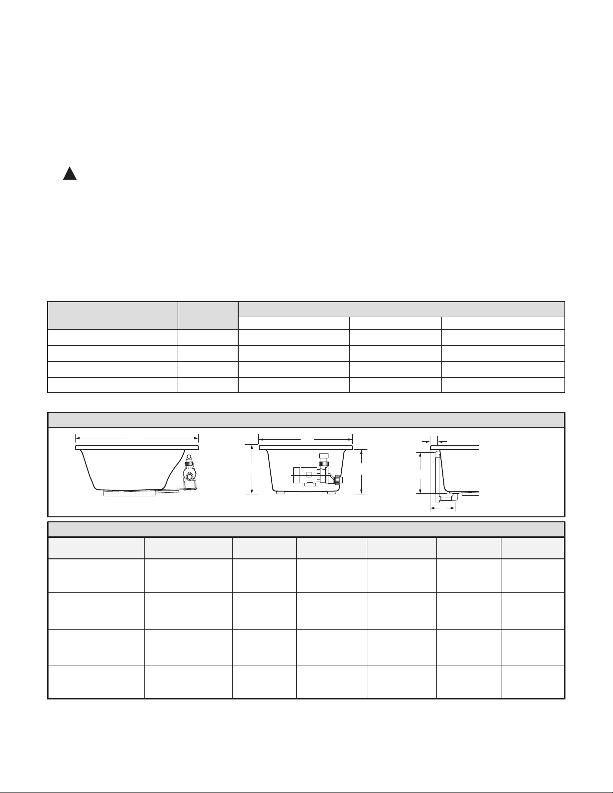
TABLE 1: GENERAL SPECIFICATIONS FOR WHIRLPOOLS AND BATH TUBS
SIDE VIEW
DRAIN / OVERFLOW
END VIEW
L
H
W
C
A
B
J
51
Corner
71
' x "
Oval
4
' x 54"
A 1-/"
(40 mm)
B 4"
(10 mm)
A 15-1/"
(4 mm)
B 10"
(54 mm)
A 1-1/"
(470 mm)
B 15-/4"
(400 mm)
A 17"
(4 mm)
B "
(14 mm)
1-5/"
(1mm)
"
(15mm)
-1/4"
(10mm)
N/A
C 1"
(4 mm)
C 0-1/4"
(514 mm)
C "
(54 mm)
C 1-/4"
(55 mm)
See Pier
Cutout
Dimensions
70-1/"
(171 mm)
x 4-1/"
(7 mm)
See Pier
Cutout
Dimensions
70-1/"
(171 mm)
x 5"
(14 mm)
N/A
7-/1"
(1 mm)
x 4-1/"
(7 mm)
N/A
7-/1"
(1 mm)
x 5-1/"
(14 mm)
L 4-1/" (14mm)
W 0-1/" (157mm)
H 0-1/" (51mm)
L 7" (1mm)
W " (14mm)
H 1-/4" (55mm)
L 7" (1mm)
W 4" (107mm)
H 5-1/" (4mm)
L 7" (1mm)
W 54" (17mm)
H -1/4" (51mm)
Description
Drain / Overflow
Cut Out Pier
G x F
Rough-In Recess
E x D
Tub Edge to
Centerline Overflow:
J
Height to
Underside of Deck:
C
Dimensions
L-W-H
754407-100 Rev. B
4
Page 5
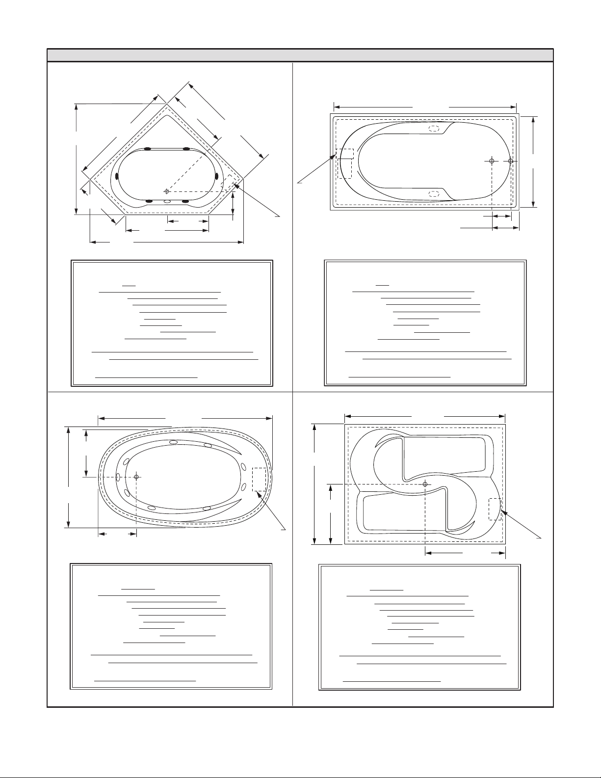
ROUGHING-IN REFERENCES
CORNER DUET WITH SEAT 60" x 60" (MODEL 2351)
CONTEMPO OVAL (MODEL 2383)
FREE SPIRIT 6' x 54" (MODEL 2466)
CENTURION 6' x 36" (MODEL 2371)
GENERAL SPECIFIC ATIONS FOR 2351
84- 1/2 x 60-1 /2 x 20 -1/2 In.(2 146 x 1 537 x 521m m)
145 Lbs. (66 Kg. )
895 Lbs. (406 Kg .)
90 Gal. (341 L)
40 Gal. (151 L)
55- 1/2 x 28-3 /4 In. (1410 x 73 0mm )
62 x 49- 3/4 I n. (157 5 x 1 264mm )
13- 3/8 I n. (3 40m m)
25 Lbs./ Sq.Ft . ( 123 Kgs./ Sq.m)
27. 5
52
ELECTRICAL SPECIFICATIONS
INS TALLE D SIZ E
WEI GHT
WEI GHT w /WATE R
GAL . TO OVERF LOW
MIN . OPE RATIN G G AL.
BAT HING WELL AT SUMP
BAT HING WELL AT RIM
WAT ER DE PTH T O O VERF LOW
FLO OR LO ADING
(PR OJECT ED AR EA)
PTS .
CUB E (FT3)
1.4 HPR, 9.7 AMP S, 1 20V.
PUM P
GENERAL SPECIFIC ATIONS FOR 2371
72 x 36 x 21- 3/4 In. (1829 x 91 4 x 552 mm)
100 Lbs. (45 Kg. )
625 Lbs. (283 Kg .)
63 Gal. (238 L)
47 Gal. (178 L)
54 x 19- 1/4 I n. (137 2 x 4 89mm)
63- 1/4 x 29-1 /2 In. (1607 x 74 9mm )
15- 1/2 I n. (3 94m m)
35 Lbs./ Sq.Ft . ( 169 Kgs./ Sq.m)
17. 2
38
ELECTRICAL SPECIFICATIONS
INS TALLE D SIZ E
WEI GHT
WEI GHT w /WATE R
GAL . TO OVERF LOW
MIN . OPE RATIN G G AL.
BAT HING WELL AT SUMP
BAT HING WELL AT RIM
WAT ER DE PTH T O O VERF LOW
FLO OR LO ADING
(PR OJECT ED AR EA)
PTS .
CUB E (FT3)
1.4 HPR, 9.7 AMP S, 1 20V.
PUM P
GENERAL SPECIFIC ATIONS FOR 2383
72 x 42 x 25- 1/2 In. (1829 x 10 67 x 64 8mm)
100 Lbs. (45 Kg. )
841 Lbs. (382 Kg .)
89 Gal. (337 L)
41 Gal. (155 L)
48 x 26- 1/2 I n. (121 9 x 6 73mm)
60- 3/4 x 35-3 /4 In. (1543 x 90 8mm )
18- 1/2 I n. (4 70m m)
40 Lbs./ Sq.Ft . ( 196 Kgs./ Sq.m)
17. 2
48
ELECTRICAL SPECIFICATIONS
INS TALLE D SIZ E
WEI GHT
WEI GHT w /WATE R
GAL . TO OVERF LOW
MIN . OPE RATIN G G AL.
BAT HING WELL AT SUMP
BAT HING WELL AT RIM
WAT ER DE PTH T O O VERF LOW
FLO OR LO ADING
(PR OJECT ED AR EA)
PTS .
CUB E (FT3)
1.4 HPR, 9.7 AMP S, 1 20V.
PUM P
GENERAL SPECIFIC ATIONS FOR 2466
72 x 54 x 23- 1/4 In. (1829 x 13 72 x 59 1mm)
130 Lbs. (59 Kg. )
121 3 Lbs . (55 0 K g.)
130 Gal. (492 L)
92 Gal. (348 L)
50 x 42 In. ( 127 0 x 1067m m)
64- 1/2 x 43-3 /4 In. (1638 x 11 1mm )
15- 1/2 I n. (3 94m m)
45 Lbs./ Sq.Ft . ( 219 Kgs./ Sq.m)
27. 5
62
ELECTRICAL SPECIFICATIONS
INS TALLE D SIZ E
WEI GHT
WEI GHT w /WATE R
GAL . TO OVERF LOW
MIN . OPE RATIN G G AL.
BAT HING WELL AT SUMP
BAT HING WELL AT RIM
WAT ER DE PTH T O O VERF LOW
FLO OR LO ADING
(PR OJECT ED AR EA)
PTS .
CUB E (FT3)
2.1 HPR, 13.5 AM PS, 120V.
PUM P
34"
(864mm)
59-3/4"
(1518mm)
59-3/4"
(1518mm)
60-1/2"
(1537mm)
45-1/2"
(1156mm)
84-1/2"
(2146mm)
22-1/4"
(565mm)
12-5/8
(321mm)
PUMP
LOCATION
27-1/2"
(699mm)
PUMP
LOCATION
72"
(1829mm)
36"
(914mm)
10"
(254mm)
6"
(152mm)
15-3/4"
(400mm)
21"
(533mm)
72"
(1829mm)
42"
(1067mm)
PUMP
LOCATION
36"
(914mm)
72"
(1829mm)
PUMP
LOCATION
54"
(1372mm)
27"
(686mm)
5
754407-100 Rev. B
Page 6
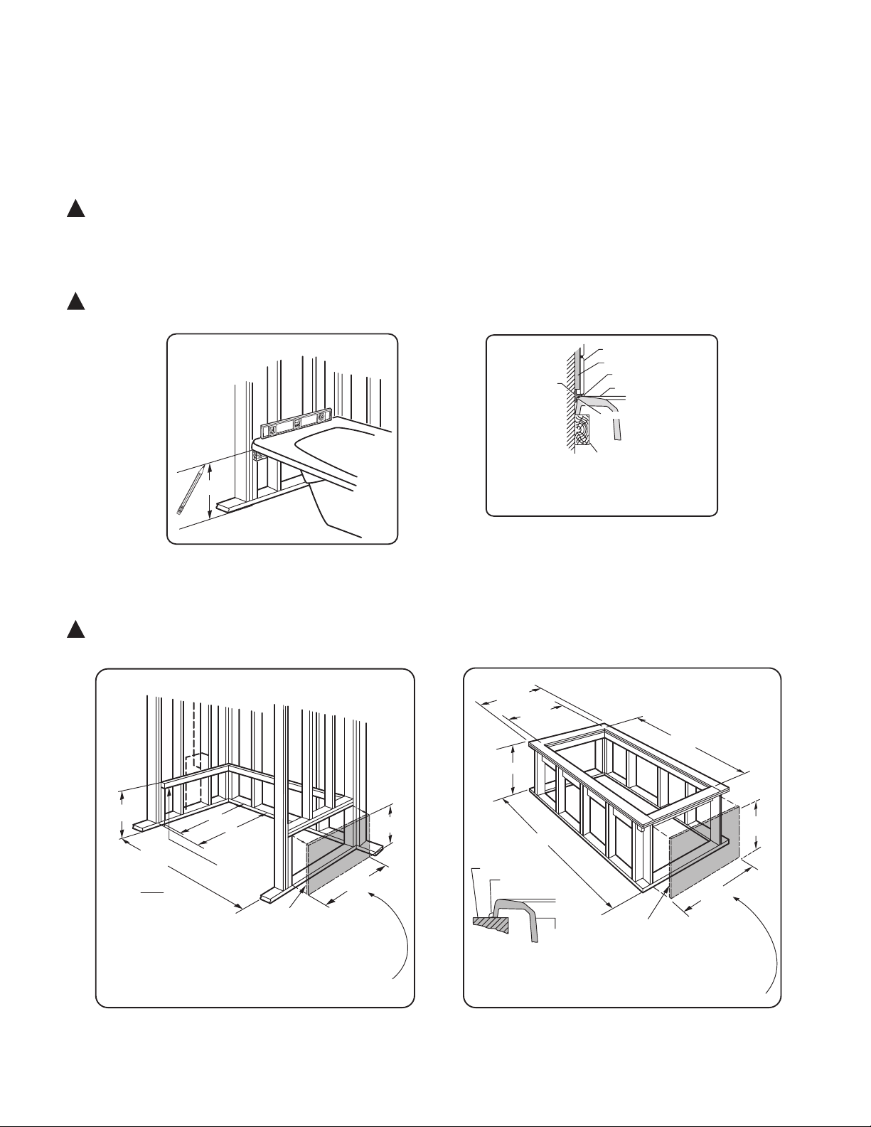
INSTALLATION AND FRAMING INSTRUCTIONS
The variety of installations possible for this whirlpool may require framing procedures other than those shown. Locate studs as needed. Ensure
roughing-in dimensions are proper, plumb and square. Provisions must be made in all installations for an access opening for servicing the pump
and controls. It is strongly recommended that an additional opening be provided for access to the drain components. The apron should not be used
as the primary access opening.
TYPICAL PIER TYPE INSTALLATION
AS DESIRED
F
CUTOUT
AS DESIRED
G
CUTOUT
C
4
(10 mm)
1
(05 mm)
MOUNTING
SURFACE
WATERPROOF
SEALANT
BATH
TYPICAL RECESS INSTALLATION
4
(10 mm)
1
(05 mm)
C
E
D
W
LEVELING
STRINGERS
TILE
TILE
BEAD
STRIP
LEVELING STRINGER
1 x 4 (not for support)
BATH
ADHESIVE
SEALANT
WALLBOARD
NOTE: Tile bead kit not included and
must be purchased separately.
C
TYPICAL INSTALLATION
FIGURE 1
Replace whirlpool and re-shim the integral support feet, shimming the entire length of the support feet. Secure the shims using construction
adhesive, silicone, mortar or equivalent materials. While not a necessity, the use of a foundation base consisting of cement, mortar, or grout
will help provide a solid and secure installation.
. Install drain components to the whirlpool following the drain installation instructions. Before replacing your whirlpool for final installation, be
certain that an opening has been provided in the sub-floor for the drain. See the roughing-in drawing and Table 1 for suggested opening
size (shadowed) and location dimensions. The drain/overflow of the bath extends below the bottom of the bath. Note that this requires a
cutout in the floor.
The floor structure beneath the bath must be able to support a total weight of bath, water, and bather. Refer to Table 1 under total weight for
your model.
. Remove the whirlpool and attach a 1 x 4 stringer to the studs, with the top of the stringer touching the traced line.
The rim of the bath must not support weight.
1. Position the whirlpool into the installation opening and level the deck in both directions, shimming the integral support feet IF necessary.
Mark the final position of the underside of the deck by tracing a line on to the studs (see Figure 1).
!
!
!
ACCESS PANEL MUST BE LOCATED
ON THE SAME SIDE AS THE MOTOR.
ALLOW OPEN FRAMING ON PUMP/MOTOR
END FOR SERVICE.
ACCESS PANEL MUST BE LOCATED
ON THE SAME SIDE AS THE MOTOR.
ALLOW OPEN FRAMING ON
PUMP/MOTOR END FOR SERVICE.
FOR E & D DIMENSIONS SEE TABLE 1 ON PAGE 5.
FOR G & F DIMENSIONS SEE TABLE 1 ON PAGE 5.
NOTE:
FRONT EDGE
OF BATH MUST
BE SUPPORTED
BY STUD WALL OR
AMERICAN STANDARD
APRON KIT
The rim of the bath must not support weight. If foundation base is used, allow the bedding material to completely harden before applying weight
to the rim or bottom of the bath. Any finish material such as tile or wall board must be self-supporting if it contacts the deck of the bath.
UNLESS AN ACCESS OPENING OF AT LEAST 12" X 24" (305 X 610mm)
IS PROVIDED, WARRANTY SERVICE WILL NOT BE PERFORMED.
UNLESS AN ACCESS OPENING OF AT LEAST 12" X 24" (305 X 610mm)
IS PROVIDED, WARRANTY SERVICE WILL NOT BE PERFORMED.
(EXCEPT 2425 WHERE APRON IS PRIMARY ACCESS OPENING)
ACCESS PANELS NOT REQUIRED
FOR BATH TUBS.
ACCESS PANELS NOT REQUIRED
FOR BATH TUBS.
754407-100 Rev. B
Page 7
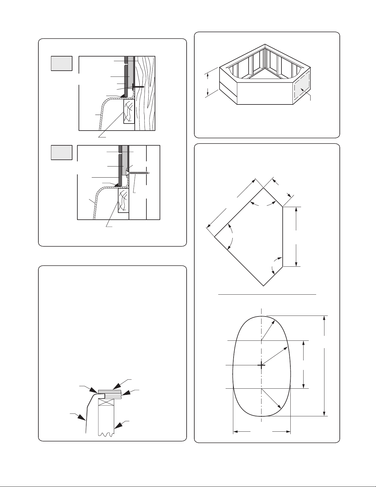
SUGGESTED WHIRLPOOL / BATH
INSTALLATION METHOD
SECURE THE BATH TO THE STUDS AS SHOWN
FOR WOOD OR STEEL STUD CONSTRUCTION.
TYPICAL FLANGE MOUNTING DETAIL
UNLESS AN ACCESS OPENING OF AT LEAST
12" x 24" (305 x 610mm) IS PROVIDED,
WARRANTY SERVICE WILL NOT BE PERFORMED.
1
(4mm)
WHIRLPOOL
ACCESS PANEL
UNDER DECK MOUNTING INSTRUCTIONS
Please note that care must be taken to protect the surface of the tub
during all aspects of the installation.
Do not drill or cut the bath deck with the tub directly beneath it as
damage to the tub may result.
1. Install the tub per the installation instructions provided with the
unit.
. Prepare the bath deck support structure per the local codes.
Note - the bath deck must be self supporting.
. Cut bath deck to your specifications.
4. Place the bath deck in position and trace the opening on the tub
with a soft pencil. Do not drill or cut the bath deck with the tub
directly beneath it as damage to the tub may result.
5. Remove the bath deck and apply a generous bead of waterproof
sealant on the outer edge of the traced line.
. Replace the bath deck and secure it into place.
7. Apply additional sealant along the tub and bath deck interface as
necessary to ensure a watertight seal.
. Remove excess sealant per the manufacturer's instructions.
Finished bath deck
surface material must be
self-supporting and
secured per local codes
Tub support structure
per installation
instructions provided
with the tub
Bath deck
support material
Bathtub
Waterproof
Sealant
STUD
WATER PROOF DRYWALL
OR CE MENT BOARD
WATERPROOF DRYWALL
OR CEMENT BOARD
TILE
SEALA NT
TUB
ROOFI NG NAIL
1 x (5 x 7mm) WOOD
STRINGER FULL LENGTH
1 x (5 x 7mm) WOOD
STRINGER FULL LENGTH
STEEL
STUD
WASHER
TILE
SEALANT
TUB
4" (10mm)
DRYWALL
SCREW
WOOD
STUDS
STEEL
STUDS
TYPICAL INSTALLATION - CORNER
PIER CUTOUTS
L
Drain
End
17" R
(4mm)
C
-5/1" R
(44mm)
1" R
(4mm)
40"
(101mm)
4"
(4mm)
70"
(177mm)
57-1/4"
(1454mm)
45-/4"
(11mm)
0˚
10˚
0˚
5"
(5mm)
Installation of a whirlpool in a platform requires a cutout.
Many whirlpools need only a rectangular cutout. Some whirlpools
require a more elaborate cutout. Illustrated below are diagrams
for those cutouts.
MODEL 2351
MODEL 2383
7
754407-100 Rev. B
Page 8
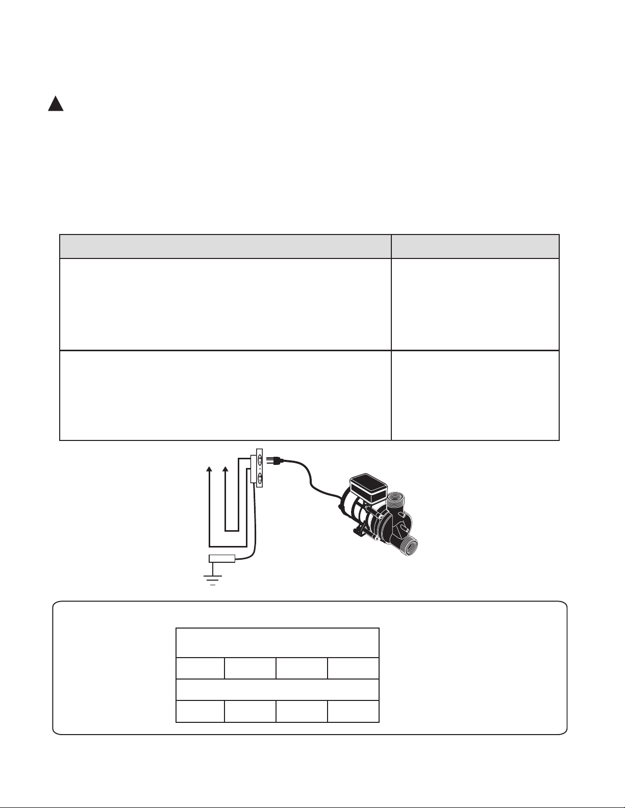
All wiring must be performed by a licensed electrician in accordance with the national electrical code and all other applicable codes.
WARNING: When using electrical products, basic precautions should always be observed, including the following:
1. DANGER: RISK OF ELECTRIC SHOCK! Connect only to a circuit protected by a ground-fault circuit interrupter.
. Grounding is required. The unit should be installed by a licensed electrician and grounded.
. Permit access for servicing motor as noted.
4. All building materials and wiring should be routed away from the pump body and heater (if equipped).
WHIRLPOOL ELECTRICAL INSTALLATION INSTRUCTIONS
ELECTRICAL DIAGRAM
READ AND FOLLOW ALL INSTRUCTIONS
BL AC K
WH IT E
120 VA C
GND .
PUMP/MOTOR
WIRE S E L E C T I O N GUIDE
Maxim u m d i s t a nce from
fuseb o x t o m o tor
The s i z e s s h o wn on th i s
chart a r e r e c ommendat i o n s
for c o p p e r c o nductors
only. A l w a y s follow
local a n d n a t ional
elect r i c a l c o des
Motor
Hi Pe r f o r m a n c e
Ratin g
2.1 H . P . ,
1.4 H . P . ,
and 1 . 2 5 H . P .
50' 100'
115V P o w e r L i ne
150' 20 0 '
12 10 8 8
!
The whirlpool should be installed on a 120 vac,
15
amp dedicated
GFCI circuit.
The circuit should be hard-wired from the electrical power supply panel. The
circuit must be a three () wire circuit from the electrical supply panel. A
grounded neutral wire and a third wire, earth ground, are essential.
Optional heater requires a separate 15 amp maximum GFCI circuit.
The whirlpool should be installed on a 120 vac, 20 amp dedicated
GFCI circuit.
The circuit should be hard-wired from the electrical power supply panel. The
circuit must be a three () wire circuit from the electrical supply panel. A
grounded neutral wire and a third wire, earth ground, are essential.
Optional heater requires a separate 15 amp maximum GFCI circuit.
GFCI CIRCUIT REQUIREMENTS: FOR MODEL NUMBERS:
2351
2371
2383
2466
PLEASE SEE THE FOLLOWING TABLE FOR GFCI CIRCUIT REQUIREMENTS:
754407-100 Rev. B
Page 9

DRAIN CONNECTION AND SYSTEM TEST
Using recommended drain assembly, connect whirlpool drain to waste line in accordance with the drain assembly instructions.
Tighten all drain joints securely. Check the pump couplings and make sure they are hand-tight. Clean the whirlpool and fill with
water to a point " above the top of the highest jet. Recheck the pump couplings and make certain that they are not leaking.
(Although the pump couplings are factory tightened and inspected, some loosening may have occurred during transit.) Make sure
the whirlpool is connected to the electrical supply and turn the whirlpool on. Check for leaks around all piping connections while the
whirlpool is running.
POST INSTALLATION CLEAN-UP
Remove all construction debris from bath. Tile grout can be removed with a wooden popsicle stick or tongue depressor. Do not use
wire brushes or any other metal implement on bath surface.
Post installation clean-up generally can be completed using warm water and liquid dishwashing detergent. Stubborn dirt or stains
may be removed using granular Spic and Span® mixed with water.
Painter's naphtha can be used to remove excess adhesives and/or wet oil-base paint.
AFTERCARE and CLEANING
• The high gloss surface is resistant to impact and chemicals and will retain its lasting luster with proper care and
maintenance.
• Always fill the tub with temperate water. Excessively hot water may cause surface damage
• Remove bath mat after use and hang to dry. Allowing bath mat to dry in the tub may cause surface damage.
• Clean after use with a mild liquid household detergent cleaner. Do not use Lestoil, Lysol Disinfectant (spray or
concentrate), or Lysol Basin, Tub and Tile Cleaner, Windex, Mr. Clean, Dow Disinfectant Bathroom Cleaner, or
cleaning products in aerosol cans.
HARSH CHEMICALS SHOULD NEVER BE USED ON ACRYLIC SURFACES.
• Do not use wire brushes, knives or sharp objects to remove stains, cigarette tar deposits,or other surface blemishes.
• Abrasive cleaners or powders must not be used, since they will dull the surface. If the glossy surface looses
its sheen, dulled areas can be restored by rubbing with a white "automotive type" polishing compound and
waxing with a "liquid wax."
• Do not wax areas where you walk or stand.
• Do not allow nail polish remover, acetone, dry cleaning fluid, paint remover or other solvents to come into
contact with the surface.
• Clean the surrounding surface immediately after using caustic drain cleaners.
• Burning cigarettes will damage the surface.
• Should damage to the fixture occur, repairs can be made quickly and easily.
Your distributor or builder can provide details.
• Do not permit drain cleaner to enter the circulation system.
CIRCULATION SYSTEM CLEANING-PURGING PROCEDURES
STEP 1. Once every month purge and clean the circulating system. Fill whirlpool with warm water and add two teaspoons
of dishwasher detergent and one-half cup of house hold bleach.
STEP 2. Activate whirlpool system in accordance with operating instructions or two minutes.
STEP 3. Drain and refill whirlpool with cool water and circulate for additional five minutes.
STEP 4. Drain whirlpool completely.
754407-100 Rev. B
Page 10

B
y Mail: American Standard Inc.
P.O. Box 5
West Caldwell, N.J. 07007
Attention: Customer Care Center
AS AMERICA, INC. (AMERICAN STANDARD) LIMITED LIFETIME WARRANTY
FOR ACRYLIC WHIRLPOOLS
AS America (“American Standard”) warrants to the original consumer purchaser that it will, at its option, repair or replace this whirlpool or any
of its parts that are found by American Standard, in its sole judgment, to be defective under normal residential use and maintenance so long
as it is owned by the original consumer purchaser.
This warranty shall only become effective upon receipt by American Standard of a completely filled out Warranty Registration Card evidencing
proof of purchase.
THIS WARRANTY SHALL BE VOID IF THE ACCESS PANEL TO THE WHIRLPOOL IS COVERED IN ANY MANNER CONTRARY TO THE
INSTALLATION INSTRUCTIONS. In no event will American Standard be liable for the cost of repair or replacement of any installation
materials including but not limited to tiles, marble etc.
This limited warranty DOES NOT COVER the following:
1. Defects or damages arising from shipping, installation, alterations, accidents, abuse, misuse, lack of proper maintenance and cleaning as
directed in the owner’s manual and use of other than genuine American Standard replacement parts, in all cases whether caused by a
plumbing contractor, service company, the owner or any other person.
. Deterioration through normal wear and tear and the expense of normal maintenance.
. Commercial application.
4. Options and accessories. American Standard’s limited warranty on these items is one year for parts only and excludes labor. This one
year limited warranty covers accessories manufactured by American Standard (e.g. aprons, drains, grab bars, heaters, trim kits) against
defects of material or workmanship. Warranty coverage begins on the date the accessory was originally purchased by the owner.
5. Postage or shipping costs for returning products for repairs or replacement under this limited warranty and labor or other costs incurred in
connection with product removal or installation under this limited warranty.
. ANY LIABILITY FOR CONSEQUENTIAL OR INCIDENTAL DAMAGES, ALL OF WHICH ARE HEREBY EXPRESSLY DISCLAIMED, OR
THE EXTENSION BEYOND THE DURATION OF THIS LIMITED WARRANTY OF ANY IMPLIED WARRANTIES, INCLUDING THOSE OF
MERCHANTABILITY OR FITNESS FOR AN INTENDED PURPOSE. (Some jurisdictions do not allow limitations on how long an implied
warranty lasts, or the exclusion or limitation of incidental or consequential damages, so these limitations and exclusions may not apply to you.)
7. Responsibility for compliance with local code requirements. (Since local code requirements vary greatly distributors, retailers, dealers,
installation contractors and users of plumbing products should determine whether there are any code restrictions on the installation or use of a
specific product.)
This warranty gives you specific legal rights. You may have other legal rights that vary from state to state. For service under this warranty, you
should contact the following:
By Telephone:
1-800-442-1902
If inspection of this AS American, Inc. (“American Standard”) plumbing product, within one year after its initial purchase, confirms that it is
defective in materials or workmanship, American Standard will repair or, at its option, exchange the product for a similar model.
This warranty applies only to the original purchaser and installation of these products.
This limited warranty does not apply to local building code compliance. Since local building codes vary considerably, the purchaser of this
product should check with a local building or plumbing contractor to insure local code compliance before installation.
This warranty shall be void if the product has been moved from its initial place of installation; if it has been subjected to faulty maintenance,
abuse, misuse, accident or other damages; if it was not installed in accordance with American Standard's instructions; or if it has been
modified in a manner inconsistent with the product as shipped by American Standard.
American Standard's option to repair or exchange the product under this warranty does not cover any labor or other costs of removal or
installation, nor shall American Standard be responsible for any other incidental or consequential damages attributable to a product
defect or to the repair or exchange of a defective product, all of which are expressly excluded from this warranty. (Some states or
provinces do not allow the exclusion or limitation of implied warranties, so this exclusion may not apply to you.)
This warranty gives you specific legal rights. You may have other statutory rights that vary from state to state or from province to province, in
which case this warranty does not affect such statutory rights.
For service under these warranties, it is suggested that a claim be made through the contractor or dealer from or through whom the product
was purchased, or that a service request (including a description of the product model and of the defect) be sent to:
AS AMERICA, INC. (AMERICAN STANDARD) ONE YEAR LIMITED WARRANTY
FOR E-Z INSTALL WHIRLPOOL HEATER
Product names listed herein are trademarks of AS America, Inc.
© AS America, Inc. 00
HOTLINE FOR HELP
For toll-free information and answers to your questions, call 1 (800) 442-1902
weekdays: :00 a.m. to 5:00 p.m. Eastern Time
SERVICE: For service or repair contact the number below. The model number and
serial number for your whirlpool are located on a label near the motor.
By Mail: American Standard Inc.
P.O. Box 5
West Caldwell, N.J. 07007
Attention: Customer Care Center
By Telephone:
1-800-442-1902
754407-100 Rev. B
10
 Loading...