

Page 1
Installation
Instructions
METERING
SPREAD LAVATORY
FAUCETS
Thank you for selecting American-Standard...the
benchmark of fine quality for over 100 years.
To ensure that your installation proceeds smoothly--please
read these instructions carefully before you begin.
TOOLS REQUIRED
1340.725
1340.825
1340.855
1340.865
1340.725
1340.825
1340.855 1340.865
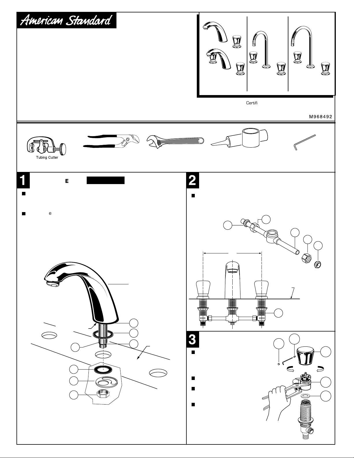
Certified to comply with ANSI A112.18.1M
SPOUT ASSEMBLY
Install RING WASHER (1) into SPOUT (2) recess. Check
that O-RING (3) on end of SPOUT SHANK (4) is in place. Insert
SPOUT SHANK (4) into center hole on mounting surface.
Assemble RUBBER WASHER (5) and BRASS WASHER (6) and
LOCKNUT (7) onto SPOUT SHANK (4). Align SPOUT ASSEMBLY.
From underside of ledge, tighten LOCKNUT (7) to secure SPOUT
ASSEMBLY to mounting surface.
SPOUT RECESS
4
5
6
7
CAUTION
Turn off hot and cold water
supplies before beginning.
SPOUT
ASSEMBLY
2
1
3
MOUNTING
SURFACE
Plumbers' Putty or CaulkingAdjustable Wrench 2.5mm Hex Wrench Channel Locks
PREPARE TUBE AND TEE ASSEMBLY
Remove COUPLING NUT (1) and FERRULE (2) from each
VALVE (3) and slide onto TUBING (4).
1
2
4
8"
MOUNTING
SURFACE
3
REMOVE HANDLE AND
!
ACTUATOR ASSEMBLY
Remove HANDLE (1) by
removing INDEX BUTTON (2)
and SET SCREW (3) with a
2.5mm hex wrench.
Pull off HANDLE (1).
Remove ACTUATOR
ASSEMBLY (4).
Remove WASHER (5).
3
2
REMOVE REPLACE
1
2
1
4
5
NOTE; Washer (5) may remain
inside of Actuator Assembly.
Page 2
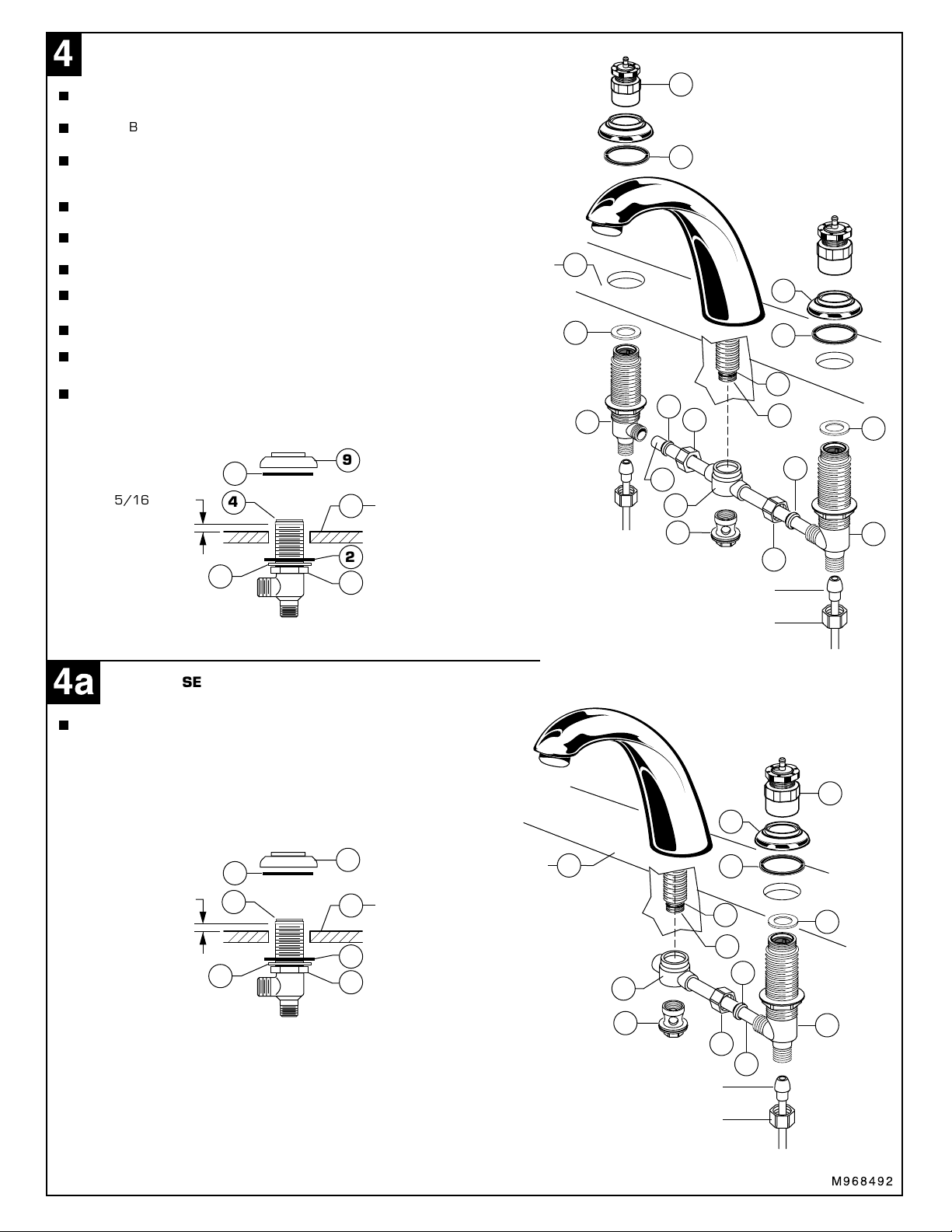
VALVE ASSEMBLY (1340.825; 1340.855; 1340.865)
"
Install LOCKNUTS (1), METAL WASHERS (3) and RUBBER WASHERS (2)
onto valve shanks.
Push TUBING (14) ends into VALVE (4) side outlets. Insert VALVES (4)
into mounting holes from underside of ledge.
Press TEE (5) onto SPOUT SHANK (6) making certain that the O-RING (7) is
properly seated on SHANK (6). Push COUPLING (8) into TEE (5) and
attach to SPOUT SHANK (6) and tighten.
Thread of VALVE BODY (4) should extend at least 5/16 inch above
MOUNTING SURFACE (11). If necessary, adjust LOCKNUT (1).
Place RUBBER RING (10) into ESCUTCHEONS (9) and thread onto valves
until snug against internal stop.
Tighten LOCKNUT (1) to secure VALVE (4) position.
Slide FERRULE (12) and COUPLING NUT (13) to outlet of VALVE (4)
and tighten COUPLING NUT (13) firmly.
Place WASHER (16) on top of VALVE ASSEMBLY (4).
Thread VALVE ACTUATORS (15) onto VALVES (4) and torque VALVE
ACTUATOR 12-15 ft. lbs, (12-20Nm).
Connect water supply to VALVES (4) with 1/2" IPS FLEXIBLE SUPPLIES or
3/8" O.D. BULL-NOSE RISERS. Use adjustable wrench to tighten connections.
Do not over tighten. Be careful not to kink copper supply when bending. Use
tubing cutter to cut to proper length.
9
10
5/16'' MIN.
4
11
MOUNTING
SURFACE
2
3
1
MOUNTING
SURFACE
15
10
11
16
12
4
HOT
13
14
5
8
1/2" IPS FLEXIBLE SUPPLIES or
3/8" O.D. BULL-NOSE RISERS
COUPLING NUT
13
9
10
7
6
16
12
4
COLD
"=
VALVE ASSEMBLY (1340.725)
For Cold or Tempered Water Supply
Valve assembly is same as two handle lavatory faucets. See above
instructions for assembly, (1340.725 Single Valve Faucet) is for Cold
or Tempered water only.
9
10
5/16'' MIN.
4
11
MOUNTING
SURFACE
2
3
1
MOUNTING
SURFACE
11
5
8
1/2" IPS FLEXIBLE SUPPLIES or
3/8" O.D. BULL-NOSE RISER
COUPLING NUT
13
9
10
7
6
12
14
15
16
4
COLD OR
TEMPERED
WATER
M968492
Page 3

INSTALL HANDLES
#
Remove INDEX BUTTON (1; 2) and loosen SET
SCREW (3) with a 2.5mm hex wrench.
Install HANDLES (4) onto VALVE STEM (5).
Tighten SET SCREWS (3) with 2.5mm Hex Wrench.
Replace INDEX BUTTONS. Red (1) in Left HANDLE (4)
Blue (2) in Right HANDLE (4).
TEST INSTALLED FITTING
$
1
4
3
3
4
2.5mm
HEX WRENCH
5
2
Turn on water supplies and check connections for leaks.
Remove AERATOR (1) with KEY (2) supplied.
Operate HOT and COLD HANDLES by pressing down on HANDLES.
Both Hot and Cold handles are set for approximately 8 second operating cycles.
Replace AERATOR (1).
TO ADJUST CYCLE TIME
%
Remove HANDLE (1) by removing INDEX BUTTON (2)
and SET SCREW (3) with a 2.5mm hex wrench.
Pull off HANDLE (1).
To increase cycle time, turn the gray PLASTIC ADJUSTING
KNOB (4) clockwise.
To decrease cycle time, turn the gray PLASTIC
ADJUSTING KNOB (4) counter-clockwise.
Replace SET SCREW (3), INDEX BUTTON (2) and
HANDLE (1). Test faucet for proper operation and
cycle time.
2
3
PRESS HANDLE
DOWN TO OPERATE
&
1
1
2
SERVICE
Remove HANDLE (1). Refer to Step 4 for handle removal.
Remove ACTUATOR ASSEMBLY (2).
Remove WASHER (3). Pull out VALVE ASSEMBLY (4) and
FILTER SCREEN (5).
Inspect that VALVE ASSEMBLY (4), FILTER SCREEN (5) and
VALVE SEAT (6) are clean and free from debris. VALVE
ASSEMBLY (3) and FILTER SCREEN (5) can be cleaned with
soap and water.
Replace FILTER SCREEN (5) and VALVE ASSEMBLY (4). Place
WASHER (3) on top of VALVE ASSEMBLY (4). Thread VALVE
ACTUATOR (2) onto faucet. Torque VALVE ACTUATOR (2)
to 12-15 ft. lbs (15-20 Nm).
Replace HANDLE (1).
2.5mm HEX WRENCH
TO DECREASE
CYCLE TIME
ROTATE
COUNTER-
CLOCKWISE
TO INCREASE
CYCLE TIME
ROTATE
CLOCKWISE
4
CARE INSTRUCTIONS:
DO: SIMPLY RINSE THE PRODUCT CLEAN WITH CLEAR
WATER. DRY WITH A SOFT COTTON FLANNEL CLOTH.
DO NOT: CLEAN THE PRODUCT WITH SOAPS, ACID, POLISH,
ABRASIVES, HARSH CLEANERS, OR A CLOTH WITH A
COARSE SURFACE.
1
REMOVE REPLACE
2
3
4
5
6
M968492
Page 4

METERING
Center Set Faucets
PRODUCT NUMBERS
M962390-YYYOA
HANDEL KIT
M962391-0070A
INDEX KIT
M952200-YYY0A
ACTUATOR UNIT
M913860-0070A
WASHER
M952210-0070A
VALVE
M952220-0070A
FILTER SCREEN
M962398-YYY0A
ESCUTCHEON KIT
051213-0070A
MOUNTING KIT
M962392-0070A
VALVE KIT
A911836-0070A
SEAL WASHER
030253-0070A
SPOUT MTG. KIT
1340.825
1340.725
5" GN
6" GN
M962399-YYY0A
SPOUT KIT
M962393-YYY0A
1.56 GPM AERATOR
1340.855
1340.865
024220-0070A
SUPPLY NUT
012078-0070A
VALVE COUPLING KIT
M962406-YYY0A
Replace the "YYY" with
appropriate finish code
CHROME 002
6" SPOUT KIT
028679-0070A
TUBE & TEE
ASSEMBLY
033757-0070A
TEE MTG. KIT
M962394-YYY0A
AERATOR
M962400-0070A
TUBE & TEE ASSEMBLY
(FOR 1340.725)
M962394-YYY0A
AERATOR
For toll-free information and answers to your questions, call:
IN CANADA 1-800-387-0369 (TORONTO 1-905-306-1093)
Product names listed herein are trademarks of American Standard Inc.
© American Standard Inc. 2005
HOT LINE FOR HELP
1 (800) 442-1902
Weekdays 8:00 a.m. to 8:00 p.m. EST
Weekdays 8:00 a.m. to 7:00 p.m. EST
M962405-YYY0A
5" SPOUT KIT
M968492
 Loading...