

Page 1
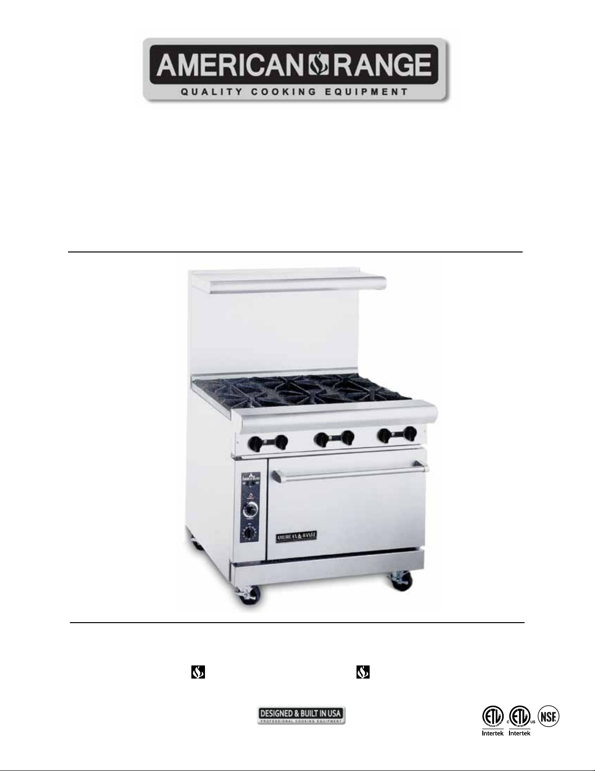
PROFESSIONAL QUALITY COOKING EQUIPMENT
DESIGN CLASS FUNCTION
OWNER’S MANUAL FOR
RESTAURANT SERIES RANGES
AR SERIES
AR-C SERIES
AR-NV SERIES
ARGF SERIES
© 2012 American Range
All Rights Reserved
13592 Desmond St., Pacoima, CA 91331 818.897.0808 tel 888.753.9898 toll free www.americanrange.com
Page 2
AR Series Ranges
Installation, Operation and
Owner’s Manual
FOR
YOUR
SAFETY
WARNING
IMPROPER
INSTALLATION
IMPORTANT SERVICE NOTICE!
Maintenance Instructions
FOR YOUR SAFETY!
Do not store or use gasoline or
WARNING!
FOR
YOUR
SAFETY
WARNING
IMPROPER
INSTALLATION
Instruction to be followed in the event the user smells gas should be posted
in a prominent location. This information should be obtained by
consulting the local gas supplier.
RETAIN THIS MANUAL FOR FUTURE REFERENCE.
13592 Desmond St., Pacoima, CA 91331 818.897.0808 tel 888.753.9898 toll free www.americanrange.com
Page 3

PROFESSIONAL QUALITY COOKING EQUIPMENT
To Our Most Valued Customer:
Congratulations on your purchase of an American Range product. We hope you will enjoy the
design, manufactured quality, innovative features and cooking performance of this product – it
represents our continuing dedication to satisfying the most demanding needs of customers
like you.
Please read this manual and become familiar with important safety information about how
to install and set-up the unit, basic operating instructions, and how to maintain that just-likebrand-new appearance and performance - over years of day-to-day use.
If you should encounter any sort of problem, turn to the section of the manual entitled,
"Troubleshooting" – for a quick solution or guidance regarding the next step required to get
back to tip-top condition.
Thank you for choosing an American Range product for your kitchen. As you can expect, this
appliance is designed for years of reliable service. If you have any questions or comments,
please contact the dealer from whom you purchased the unit, or contact American Range
Customer Service via email: [email protected] at www.americanrange.com, or call
888.753.9898.
Sincerely,
Shane Demirjian
President, American Range Corporation
13592 Desmond St., Pacoima, CA 91331 818.897.0808 tel 888.753.9898 toll free www.americanrange.com13592 Desmond St., Pacoima, CA 91331 818.897.0808 tel 888.753.9898 toll free www.americanrange.com
Page 4
Owner’s Manual AR Series Ranges
GENERAL 1
Important Safety Information .......................................................................1
Shipping Damage Claim Procedure ..........................................................1
INSTALLATION2-7
Installation, Operation & Service Personnel ......................................... 2
Ventillation Hoods ................................................................................................2
Gas Standards and Codes ..............................................................................2
Gas Connection ....................................................................................................3
Manual Shut-Off Valve .......................................................................................3
Rating Plate ..............................................................................................................3
Electric Standard & Codes .............................................................................4
Casters ....................................................................................................................... 5
Leveling ......................................................................................................................5
Typical Model & Parts Identication ..........................................................6
Installation Checklist ...........................................................................................7
OPERATING 8-10
Check for Gas Leaks ..........................................................................................8
Open Burner/Griddle/Raised Griddle Broiler .....................................8
Oven ...........................................................................................................................8
Lighting Innovection® & Convection Oven ...........................................8
Shut Down Innovection® & Convection Oven ....................................9
Final Preparation ...................................................................................................9
Hi-Shelf Installation ..............................................................................................9
Green Flame Lighting Instructions ...........................................................10
MAINTENANCE 11
Raised Griddle - Broiler .................................................................................11
Oven ........................................................................................................................11
Summary ................................................................................................................11
ExPLODED VIEW DRAWINGS/PARTS LISTS 12-15
AR Series ........................................................................................................12-13
AR-6NV ...........................................................................................................14-15
16
13592 Desmond St., Pacoima, CA 91331 818.897.0808 tel 888.753.9898 toll free www.americanrange.com
Page 5
Owner’s Manual AR Series Ranges
!
!
IMPORTANT - PLEASE READ AND FOLLOW!
• Before beginning, please read all the instructions carefully.
• DO NOT remove permanently afxed labels, warnings, or plates from product. This will void the warranty.
• All local and national codes and ordinances must be observed; installation must conform with local codes.
• The Installer must leave these instructions with the consumer who should retain for local inspector’s use and for future reference.
• Installation and service must be performed by a qualied installer, ser vice agency or gas supplier.
• Please ensure that the product is properly grounded.
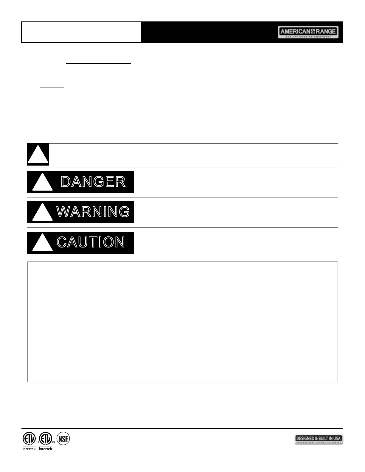
Your safety and the safety of others is very important. We have provided many important safety messages in this manual and on
your appliance. Always read and obey all safety messages.
!
DANGER
WARNING
CAUTION
!
CALIFORNIA PROPOSITION 65 WARNING
The burning of gas cooking fuel generates some by-products which are on the list of substances known by the State of
California to cause cancer or reproductive harm. California law requires businesses to warn customers of potential exposure
to such substances. To minimize exposure to these substances, always operate this unit according to the Owners Manual,
ensuring you provide proper ventilation when cooking with gas.
1
13592 Desmond St., Pacoima, CA 91331 818.897.0808 tel 888.753.9898 toll free www.americanrange.com
Page 6
Owner’s Manual AR Series Ranges
INSTALLATION
Installation of the equipment should be performed by qualied, certied, licensed and/or authorized personnel who are experienced
in state/local installation codes.
Operation of the equipment should be performed by qualied or authorized personnel who have read this manual and understand
and are familiar with the functions of the equipment.
Service of the equipment should be performed by qualied personnel who are knowledgeable with American Range products.
Means must be provided for any commercial, heavy-duty cooking appliance to exhaust combustion waste products to the outside
of the building. Usual practice is to place the unit under an exhaust hood. Filters and drip troughs should be part of any industrial
hood. Consult local codes before constructing and installing a hood.
Room air movement should be monitored during installation. Strong exhaust fans in the hood or in the overall air conditioning
system can produce a slight vacuum in the room and/or cause air drafts – either may interfere with the pilot or main burner
performance and can also be hard to diagnose. If pilot burner or main burner outage problems persist – make up air openings or
bafes may have to be provided in the room.
INSTALLATION - GAS STANDARDS AND CODES
IMPORTANT - The installation of this appliance must conform to local codes or, in the absence of local codes, with the National Fuel
Gas Code ANSI Z223.1 Natural Gas Installation Code, CAN/CGA-B149-1 or the Propane Installation Code, CAN/CGA-B149-2
as applicable, including:
1. The appliance and its individual shut-off valve must be disconnected from the gas supply piping system during any
pressure testing of that system at test pressure in excess of 1/2 psi (3.45 kPa).
2. The appliance must be isolated from the gas supply piping system by closing the individual manual shut-off
valve during any pressure testing of the gas supply piping system.
The appliance, when installed, must be wired and electrically grounded in accordance with local codes, or in the absence of local
codes, with the National Electric Code, ANSI/NFPA 70, or the Canadian Electrical Code, CSA C22.2 as applicable.
!
DANGER
2
13592 Desmond St., Pacoima, CA 91331 818.897.0808 tel 888.753.9898 toll free www.americanrange.com
Page 7
!
Owner’s Manual AR Series Ranges
A
A
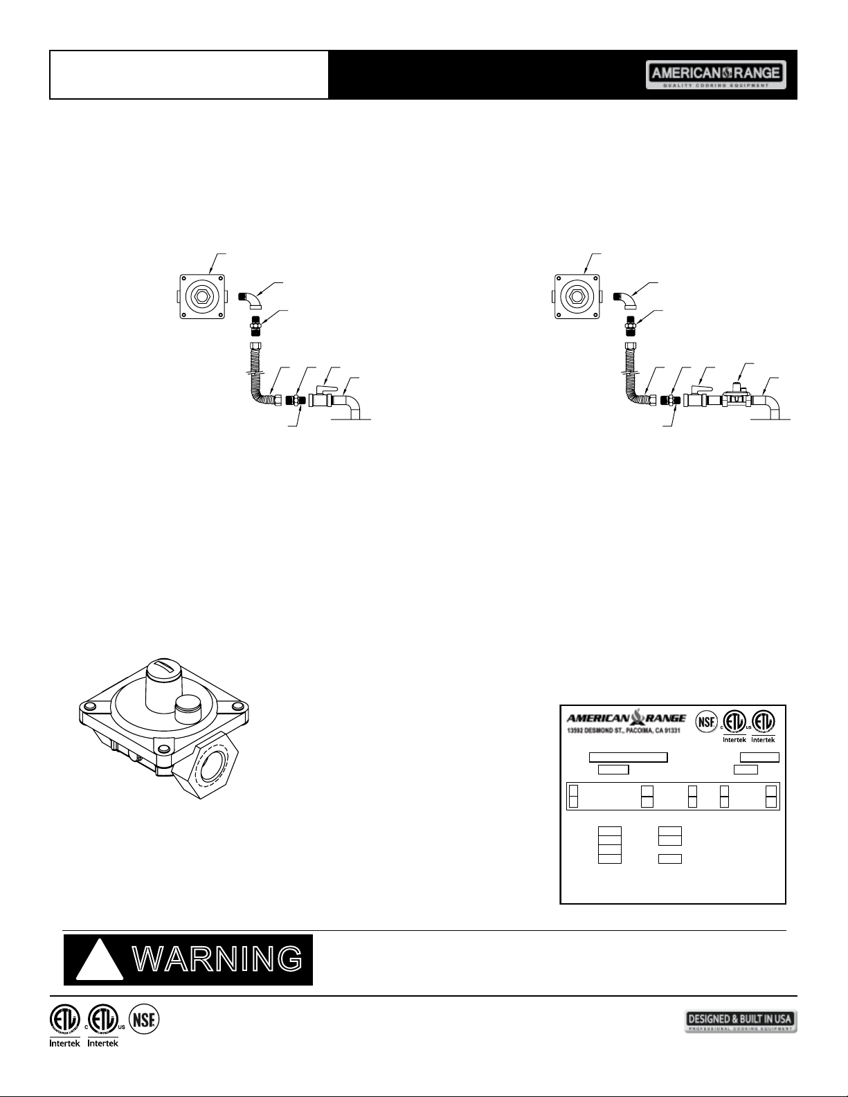
GAS CONNECTION - The single deck oven requires one gas connection; the double deck oven requires two gas connections.
The gas inlet line size of this appliance is 3/4" NPT. For proper operation, the gas service supply line must be the same size or
greater than the inlet line size of the appliance.
- A gas pressure regulator and a contractor-supplied shut-off valve must be plumbed in the gas
service line ahead of the appliance – in a physical location where it can be reached quickly in the event of an emergency.
B B
NATURAL GAS
A. Gas pressure regulator
B. 90º Street elbow
C. Adapter (must be 3/4" male pipe thread)
D. Flexible connector
E. Manual gas shut-off valve
F. 3/4" gas supply
G. Use pipe-joint compound
C
DCE
G
LP GAS
A. Gas pressure regulator
B. 90º Street elbow
C. Adapter (must be 3/4" male pipe thread)
D. Flexible connector
F
E. Manual gas shut-off valve
F. 3/4" gas supply
G. Use pipe-joint compound
H. Step down regulator
C
H
ECD
G
The gas pressure regulator must be installed in the gas line – failure to install a pressure regulator will void the equipment
warranty. The regulators supplied with ranges have 3/4" NPT connections; the regulator is adjusted at the factory for
5" W.C (water column) manifold gas pressure (natural gas) or 10" W.C. manifold gas pressure for propane gas operation.
Before connecting the regulator, check the incoming line pressure – as these regulators can only withstand a maximum inlet pressure
of 14" W.C. (1/2 PSI); exceeding this pressure will damage them. Visually double check any installer-supplied intake pipes and/or blow
them out using compressed air to clear any dirt or debris, threading chips, or other foreign matter – before installing a service line.
Those particles will clog gas orices when gas pressure is applied. Compounds used on threaded joints of this appliance piping must be
resistant to the action of NG and LP gas and provide a gas tight seal to prevent leaks. If the gas supply line pressure is greater than this
amount, a step-down regulator will be required. A gas ow direction arrow is cast into the body of the regulator to minimize installation
error – it should point downstream to the appliance. The blue air vent cap on the top of the regulator is part of the regulator and
should not be removed.
Any adjustment to the regulator must be made only by qualied and licensed service
personnel with the proper calibrated test equipment. Gas connections should be performed
by a qualied licensed contractor.
F
RATING PLATE - The information on the rating plate denes the model,
serial number, gas type (natural or liquid propane), operating pressures and burner
BTU ratings. Keep this information for future reference. It is essential for proper
identication of the unit when requesting additional information or factory support.
WARNING
3
13592 Desmond St., Pacoima, CA 91331 818.897.0808 tel 888.753.9898 toll free www.americanrange.com
AR-6-C 999999-999
MODEL: SERIAL NO.
NAT
GAS TYPE:
INNOVECTION:
CONVECTION:
X
INPUT-BTU/HOUR/BURNER CLEARANCES
OPEN TOP
V
120
V
120
32,000
20,000GRIDDLE
CON/NV
15,000BROILER
20,000HOT TOP
FOR USE ONLY ON NONCOMBUSTIBLE FLOORS
CURB MOUNT MUST HAVE 2" OVERHANG
INTENDED FOR OTHER THAN HOUSEHOLD USE
ANSI Z83.11a/CSA 1.8a-2007 Food Service Equipment
Rating Plate
MAN. PRESS: IN. W.C.
PHASE
1
PHASE
1
27,000SM. OVEN
BACK
35,000STD. OVEN
SIDES0”0”4"12"
30,000OVEN
A
A
NON-COMB. COMB.
3013256
3
5
5.0
CYCLE
CYCLE
60
60
Page 8
Owner’s Manual AR Series Ranges
!
!
INSTALLATION - ELECTRIC UTILITY CONNECTIONS - STANDARDS AND CODES
WARNING
Qualied installation personnel are individuals, a rm or a company which either in person or through a representative are engaged
in and responsible for the installation of electrical wiring from the electric meter, main control box or service outlet to the electric
appliance.
Qualied installation personnel, licensed and bonded, must be experienced in such work, familiar with all precautions required and
have complied with all requirements of state or local authorities having jurisdiction.
- All ovens, when installed, must be electrically grounded in accordance with local codes,
or in the absence of codes, with the National Electrical Code ANSI/NFPA 70 - Latest Edition and/or Canadian National Electrical
Code C22.2 as applicable.
The ventilation of these ranges should be in accordance with local codes. In absence of local codes, refer to the national ventilation
code titled, Standard for the Installation of Equipment for the Removal of Smoke and Grease Laden Vapors from Commercial
Cooking Equipment, NFPA-96-Latest Edition.
GENERAL ExPORT INSTALLATIONS - Installation must conform to Local and National Standards. Local installation codes
and/or requirements may vary. If you have any questions regarding the proper installation or operation of your American Range
Innovection® or Convection Oven, please contact your local distributor. If you do not have a local distributor, contact American
Range Corporation at 1.888.753.9898 or visit us at www.americanrange.com
ELECTRICAL CONNECTION - The standard gas operated convection ovens require a 120 VAC, 60 Hz, 15 AMP electrical service
for operation. The supply cord provided on the appliance is equipped with a three-prong (grounding) plug for protection against
electrical shock hazard. The electrical service in the building must be equipped with a properly grounded three-prong receptacle, in
accordance with local codes, or in the absence of local codes, with the National Electrical Code, ANSI/NFPA 70, or in Canada – to
Canadian electrical codes, CSA C22.2. Do not cut or remove the grounding prong from this plug.
ElECTRICAl GROUNdING INSTRUCTIONS
WARNING
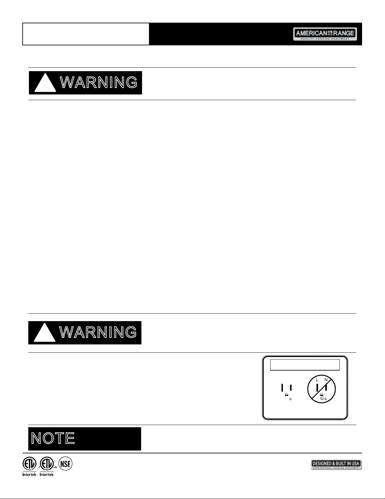
For gas red 120 VAC units and any NEC compliant receptacle, proper ground and correct
polarity is required.
Electric convection ovens are congured at the factory for operation from 208 VAC, single
phase, or 208 VAC, three-phase electrical service is also an available conguration. Consult
wiring diagram located at the end of this manual and on the back side of the appliance.
CAUTION
NL NL
G G
GOOD NO GOOD
120 VAC POLARITY SPECS A39074
NOTE
4
13592 Desmond St., Pacoima, CA 91331 818.897.0808 tel 888.753.9898 toll free www.americanrange.com
Page 9

Owner’s Manual AR Series Ranges
CASTER INSTALLATION
When installing provided casters, match holes on the caster with holes on the oven bottom base and fasten with the
hardware provided. Locking-type casters must be installed in the front.
Ovens with casters must be installed with the locking front casters supplied, a exible connector complying with ANSI Z21.69.
CGA6.16 and a quick-disconnect device complying with ANSI Z21.41CGA 6.9. Adequate means must be provided to limit the
movement of the appliance without depending on the connector and the quick-disconnect device or its associated piping to limit the
appliance movement.
LEVELING
A carpenter’s spirit level should be placed on the oven oor, and the unit leveled both front-to-back and side-to-side. If the unit is
not level, cakes, casseroles and any other liquid or semi-liquid batter will not bake evenly, burner combustion may become erratic, and
the unit will not function properly.
If the kitchen oor is relatively smooth and level, the unit may be leveled by turning the "foot" section of the leg, since casters are not
adjustable. Identify the high corner and level the unit if the adjustment required exceeds the 1-1/4" limit use metal shims.
dO NOT
CAUTION
!
All American Range Corporation appliances are adjusted and tested before leaving the factory, effectively matching them to
appropriate atmospheric conditions. We recommend that adjustments and calibrations are performed upon installation to assure
proper operation of the unit and avoid possible problems caused by rough handling or vibration during shipment. This work must be
performed only by qualied service personnel. These adjustments are the responsibility of the customer and/or dealer and are not
covered by warranty.
Check all gas connections for leaks with a soapy water solution before lighting the oven. DO NOT USE AN OPEN FLAME TO
Putting an open ame beside a new gas connection is extremely dangerous and may result in serious injury
or death.
5
13592 Desmond St., Pacoima, CA 91331 818.897.0808 tel 888.753.9898 toll free www.americanrange.com
Page 10
Owner’s Manual AR Series Ranges
OVEN THERMOSTAT
CONVECTION / INNOVECTION
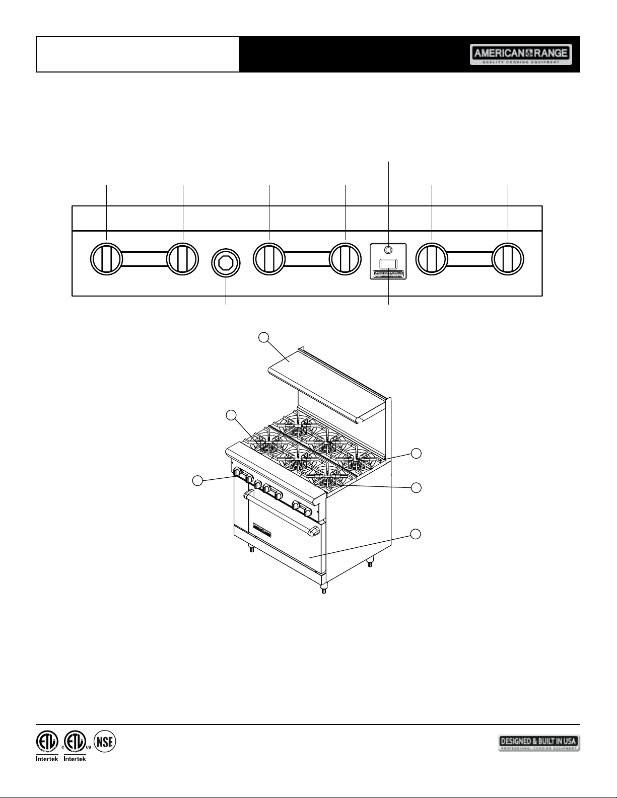
TYPICAL MODEL & PARTS IDENTIFICATION
OVEN
BURNER ON
LIGHT
BURNER
RIGHT
ON
COOL
DOWN
LEFT
REAR
FRONT
CENTER
2
CENTERLEFT
FRONT
OFF
ON
REARREAR
FRONT
RIGHT
1
3
6
4
5
Pilot
Grates
Ignition
Door
6
13592 Desmond St., Pacoima, CA 91331 818.897.0808 tel 888.753.9898 toll free www.americanrange.com
Page 11
Owner’s Manual AR Series Ranges
This checklist has been developed to assure proper installation of your oven.
To validate warranty, you must mail, e-mail or fax this form and a copy of your receipt to:
Street:___________________________________________
City, State, Zip Code:_______________________________
E-mail:__________________________________________
Telephone:______________________________________
Dealer:________________________________________
CHECK ALL THAT APPLY
0 Exterior
0 Top section
0 Oven interior
Installation
0 Read User Manual
0 Review Safety Instructions
0 Proximity to cabinets
0 Backguard in place
0 Level
0 Ventilation system
Ignition
0 Top Burners
0 Griddle
0 Char Broiler
0 Oven Burner
0 Infrared Broiler
Controls
0 Burner Knobs
0 Thermostats
0 Char Broiler
0 Convection Oven Fan & Switch
0 Oven Light Switch
0 Correct voltage
0 Grounded outlet
0 Polarized outlet
0 No GFCI
0 Verify fuel: 0 Natural -or- 0 LP
0 Gas shut-off present and accessible
0 Gas Supply line properly sized
0 Gas Supply pressure checked
0 Operating pressure checked
0 All connections checked for leaks
0 Top Burners
0 Griddle
0 Char Broiler
0 Oven Burner
0 Infrared Broiler
0 Alignment
0 Door Seal
0 Hinges
Purchase Date:___________________________________
Installation Date:__________________________________
Installer’s Name:__________________________________
Company:______________________________________
Telephone:______________________________________
0 Top Burners
0 Griddle
0 Char Broiler
0 Oven Burner
0 Infrared Broiler
0 Top Burners
0 Griddle
0 Char Broiler
0 Oven Burner
0 Infrared Broiler
7
13592 Desmond St., Pacoima, CA 91331 818.897.0808 tel 888.753.9898 toll free www.americanrange.com
Page 12
Owner’s Manual AR Series Ranges
+-
OPERATING INSTRUCTIONS
Before lighting, check all joints in the gas supply line for leaks. DO NOT USE OPEN FLAME TO CHECK FOR LEAKS!
Use soap and water solution.
1. Turn pilot valves to OFF position by turning adjustment screws clockwise.
2. Turn ON the manual gas valve at the inlet side of the gas supply line.
3. Check for gas leaks at the exible coupling or gas connector tting using a solution of one part soap and three par ts water.
4. Sparingly spray or brush the soapy solution at the gas ttings; active bubbling indicates location of gas leak.
5. If a gas leak is detected turn off the manual gas valve at the inlet side of the gas line. Call your certied and licensed service
technician.
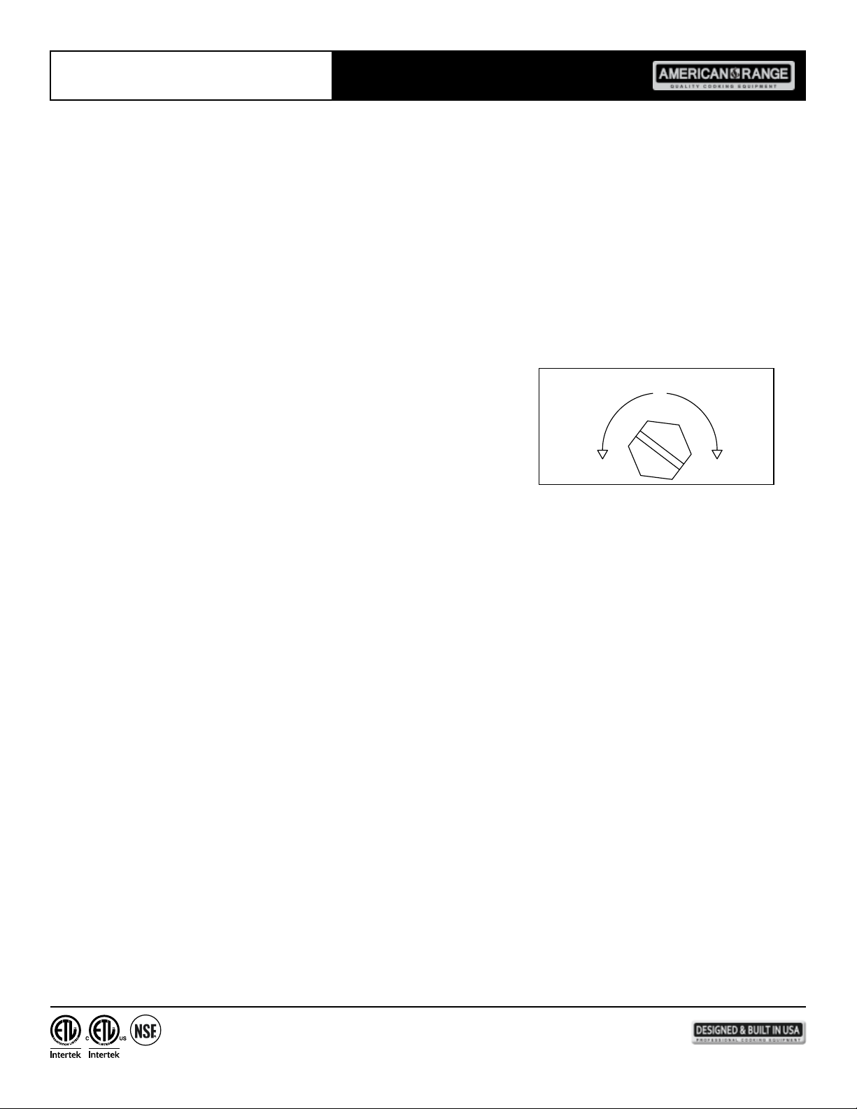
1. Turn pilot adjustment screw counter-clockwise, then light standing pilot and
adjust ame 1/4" high.
2. Turn ON gas valves to light main burners.
3. For complete shut down, shut-off gas valves and turn pilot adjustment screw
clockwise to shut-off gas to the pilots.
PILOT ADJUSTMENT SCREW
MORE GAS LESS GAS
OVEN
1. Turn thermostat to the OFF position.
2. Wait ve minutes.
3. Access the burner compartment by lifting up the kickplate and rotating forward to expose the safety valve.
4. Push in and hold the safety valve button at the bottom of the oven.
5. Light the pilot by repeatedly pressing the piezo electric ignition button; keep safety valve button pressed in until the pilot stays
lit when released.
6. If pilot goes out repeat steps 2 -5.
7. Set thermostat to desired temperature.
8. Turn the thermostat to the OFF position for complete shut down; shut-off main gas valve.
® AND CONVECTION OVENS
1. Before attempting to light this appliance, the cover, if so equipped should be open.
2. Turn OFF the manual gas valve located at the outlet side of the gas supply line.
3. Turn the manual gas supply valve to the OFF position.
4. Set the thermostat to the OFF position.
5. Press the power switch to the OFF position.
6. Wait ve minutes.
7. This appliance is equipped with an automatic spark ignition device which automatically lights the burner.
Do not try to light the burner with a match.
8. Turn the manual gas supply valve to the ON position.
9. Press the power switch to the COOK position.
10. Set the thermostat to the desired temperature. The direct spark ignitor will light the burner. If burner does not light, go
back to steps 2 - 9 above and repeat the process.
If the problem persists, call your factory personnel.
11. The cover, if so equipped, should be placed in the closed position.
12. If gas odor is detected, turn off the gas valve and follow lighting instructions beginning from step 1.
13592 Desmond St., Pacoima, CA 91331 818.897.0808 tel 888.753.9898 toll free www.americanrange.com
8
Page 13
Owner’s Manual AR Series Ranges
INNOVECTION® AND CONVECTION OVENS
1. Set the thermostat to the OFF position.
2. Press the power switch to the OFF position.
3. Turn the manual gas supply valve to the OFF position.
FINAL PREPARATION
On initial installation, turn the oven thermostat to 250ºF and operate the unit for about one hour, then reset the thermostat to its
maximum temperature and operate the unit for an additional hour. This will drive off any manufacturing oils remaining in the unit.
Let the unit cool, then thoroughly clean interior surfaces using hot soapy water.
CLEARANCES
Rear Rear
0" 0" 4" 12"
For installation on a non-combustible oor only.
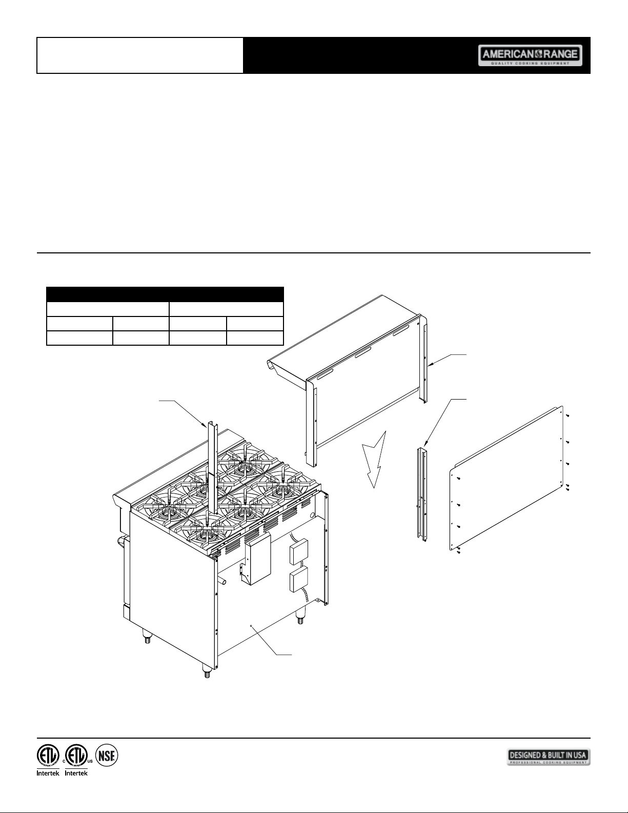
HI-SHELF ASSY
MOUNTING CHANNEL
MOUNTING CHANNEL
RANGE BODY BACK
REAR VIEW SHOWN
1. Slide hi-shelf assembly from top with mounting channels going inside the body sides.
2. Set on top of support brackets and screw to body sides at rear.
9
13592 Desmond St., Pacoima, CA 91331 818.897.0808 tel 888.753.9898 toll free www.americanrange.com
Page 14
Owner’s Manual AR Series Ranges
GREEN FLAME MODELS
Your new Green Flame Range is designed to deliver the commercial cooking performance you have come to expect from restaurant
equipment – with a difference. The difference comes from the use of innovative surface and oven burner ignition technology that
eliminates the need for standing pilot ames on the cooktop and in the oven – that burn all the time.
Lighting the Green Flame Range burners is as simple as twisting the knob to the light position – you will hear a few evenly spaced
“ticks” – that’s the electric spark working to ignite the burner. When the ticking stops, the burner is on – and sophisticated electronics
are monitoring a very small but important electrical current owing through the ions of the ame. The presence (or absence) of this
electrical current signals the electronics to automatically relight in case the burner ame is lost.
Operation of the oven is as simple – before, the chef lit a pilot ame – then activated the burner. Today, electrical contacts of the
thermostat activate an ignition circuit board – that lights and monitors the ame exactly the same way the surface burners are handled.
The Green Flame Range is an energy efcient product – in some cases saving 100’s of millions of BTU’s annually, helping to reduce the
carbon footprints of kitchen appliances. Here is a summary of operating procedures for lighting the surface and oven burners! It’s as
easy as 1-2-3!
1. Push in and turn the knob past the “FLAME” position for the burner you would like to light.
2. The automatic ignition system takes over, sparks to light the burner – and monitors the ame continuously –
automatically relighting in case it is lost.
3. Use the knob to adjust the surface burner ame light and cooking power by dialing in the desired setting.
1. Turn the Oven Thermostat to the desired temperature – typically 350ºF for baking.
2. As in the surface burners, the automatic ignition system takes over, sparks to light the burner – and monitors
the ame continuously – automatically relighting in case it is lost.
3. When nished using the oven, rotate the thermostat knob to the off position.
10
13592 Desmond St., Pacoima, CA 91331 818.897.0808 tel 888.753.9898 toll free www.americanrange.com
Page 15
Owner’s Manual AR Series Ranges
MAINTENANCE
1. Remove surface burners and clean with warm water and wire brush. Make sure the tiny burner ports are not clogged.
2. Check valves for operation and clean if necessary. Consult your service agency or local gas company.
1. Season prior to use. To season, pour a small amount of cooking oil (1 ounce / sq. ft. or 28g / .1 sq meter of surface) over the
top. With a cloth, spread oil over the entire surface to create a thin lm. Wipe off any excess oil with a cloth. Turn burner
on very low and allow oil burn off. Repeat the procedure three times before regular use.
2. Remove and empty grease pan. Clean thoroughly and replace.
3. Remove rack and grease pans. Clean with soap and water.
4. Wipe the inside clean.
5. Clean griddle plate with warm, soapy water. Rinse with warm water.
6. Turn griddle on and rinse again with warm water to boil-out any soap left at the edges of the griddle plate.
7. Repeat step one after cleaning process.
1. Remove burner assembly and clean with warm water and wire brush. Make sure the tiny burner ports are not clogged.
2. Remove griddle plate assembly and thoroughly scrape and clean the underside.
OVEN
1. Wipe clean the inside of the oven.
2. Remove oven racks and clean with soap and water.
3. Reassemble after cleaning.
4. Remove racks and rack guides (convection oven) and clean.
1. Remove burner and clean with warm water and wire brush. Make sure the tiny burner ports are not clogged.
2. Check the rear ue way and clean if any debris exists.
STAINLESS STEEL PARTS - Do not use steel wool, abrasive cloths, cleansers or powders to clean Stainless Steel surfaces. All
Stainless Steel parts should be wiped regularly with hot soapy water during the day and a Stainless Steel liquid cleaner at the end
of the day. To remove encrusted materials, soak in hot water to loosen the material, then use a wood or nylon scraper. Contact
the factory, factory representative or a local service company to perform maintenance and repairs.
MAINTENANCE SUMMARY
1. Never attempt to run oven with motor off.
2. Cool down after cooking is nished.
3. Periodically lubricate the pivot pins of the oven door hinge. Use a multi-purpose lubricating oil sparingly.
4. Door chain assembly and door bushing must be inspected periodically and adjusted or replaced to ensure
satisfactory operation of doors.
5. Clean the burner air shutter and burner chamber. Remove any accumulation of debris by hand.
6. Check blower wheel for any accumulation of debris. Remove by hand, do not use any tools.
7. Replace burned out light bulbs.
8. Excessive use will result in excessive wear and tear.
11
13592 Desmond St., Pacoima, CA 91331 818.897.0808 tel 888.753.9898 toll free www.americanrange.com
Page 16
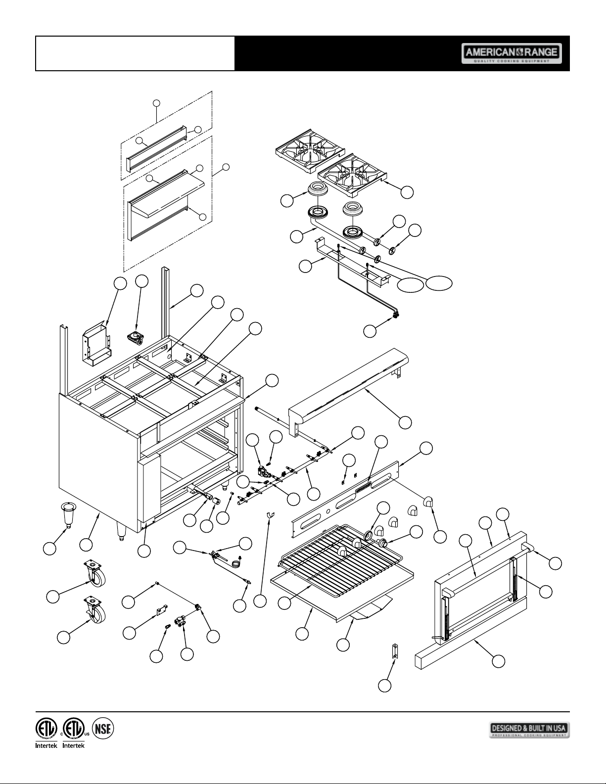
Owner’s Manual AR Series Ranges
1
3
2
6
5
4
8
7
9
10
17
16
18
19
20
21
11
15
14
13
12A
12B
22
46
23
24
44
45
47
43
25
42
41
28
32
31
30
29
26
27
40
48
53
52
49
50
51
54
33
34
35
36
23
38
37
61
39
60
59
58
56
55
57
12
13592 Desmond St., Pacoima, CA 91331 818.897.0808 tel 888.753.9898 toll free www.americanrange.com
Page 17
Owner’s Manual AR Series Ranges
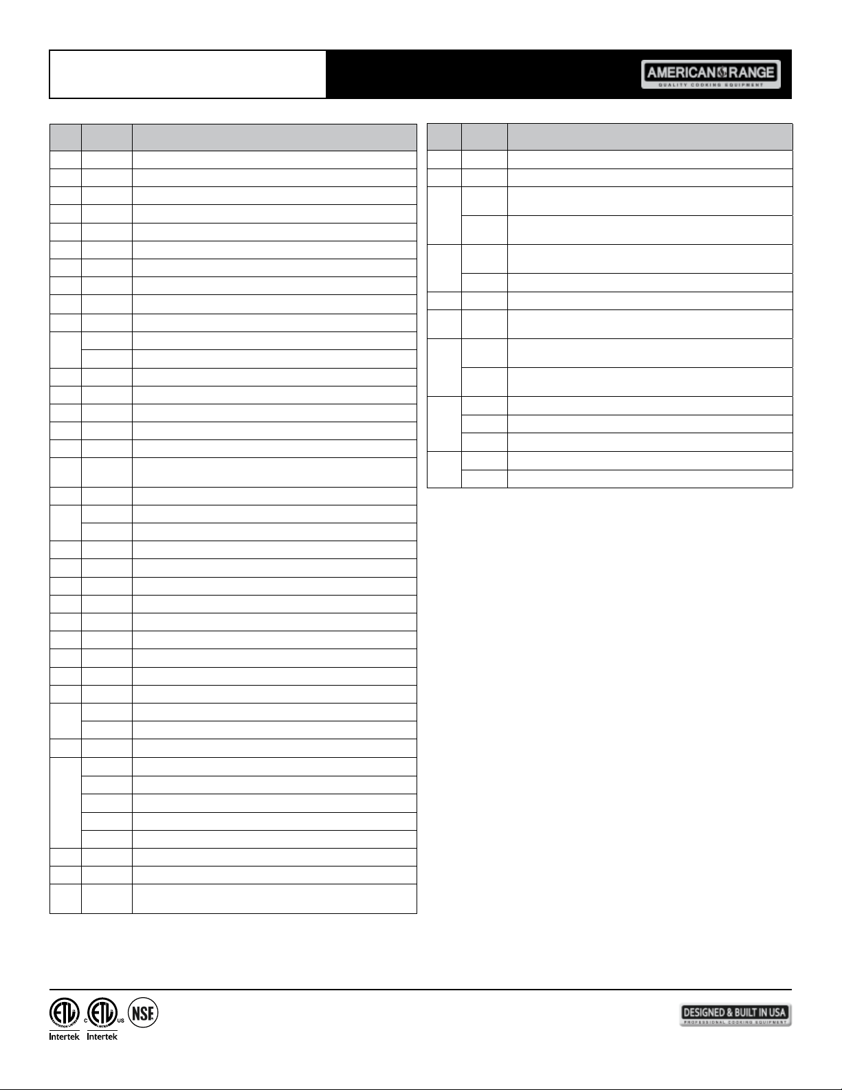
ITEM
ITEM
PART NO. DESCRIPTION
NO.
8 A14023 Burner Head, Lift Off Standard AR
9 A14024 Burner, Venturi Long Only 10447
10 A99585 Hanger, Burner AR Series 1180
11 A29301 Valve, Dual Gas Pilot 1/8 x 3/16C 10432
12A A11200 Pilot Tip, Assembly Short New Front Open Burner AR Series
12B A32012 Pilot Tip, Assembly Long New Rear Open Burner AR Series
13 A14037 Air Shutter, 2" 10464
14 A14025 Burner, Venturi Short Only 10446
A17000 Grates, Top 12" x 12" Cast Iron 10450-12
15
16 A99317 Flue, Oven AR Ranges 10207
A80011 Valve, Pressure Regulator 3/4 10481 LP Gas Set 10.0
17
A80110 Valve, Pressure Regulator 3/4 10480 Nat Gas Set 5.
18 A99602 Channel, High Rise AR Range 1037 Standard
20 A99314 Bracket, Top Grate w/Support 1181 Short Aluminized Metal
21 A99315 Bracket, Top Grate w/Support 1182 Long Aluminized Metal
22 A14048 Burner & Deector Assembly
23 A28000 Fitting, 3/8 CC x 1/4 MIP Brass 10011
A11101 Thermostat, BJ Griddle/Gas Oven 10421 1 Outlet
24
25 A23100 Nipple, Flanged BJ Thermostat 10012
A29000 Orice Hood, #39 1/2" Brass 11039
26
A29007 Orice Hood, #53 1/2" Brass
27 A14049 Air Shutter, 1" Oven Burner 10474 AR Range
28 R14020 Burner, Bake Oven ARROB/ARRSB
29 A11100 Thermocouple, 18" 2C AR Range 10485
32 A35001 Leg, 6" Cone 3" Adjustable Bullet Chrome Plated NSF
33 A35014 Caster, 4" Swivel Plate Mount No Brake NSF AR, AGBU, ACB
34 A35015 Caster, 4" Swivel Plate Mount w/Brake NSF AR, AGBU, ACB
37 A80100 Valve, Safety TS-11J AR Ranges 10425
38 A24001 Elbow, Orice Mixr 1/4Px3/8-27 10010
39 A10010 Ignitor, Piezo & Locking Nut 10434
A11104 Pilot, Nat Gas .018 5SL-2 AR/SAG 10413
40
A11132 Pilot, LP Gas AR Series Ranges 10413L SAG
41 A23010 Plug, 1/8" Pipe Hex Black All Manifolds
A15000 Manifold, 36" AR Range Standard
A15006 Manifold, 24" AR Range Standard
42
A15013 Manifold, 48" AR Range Standard
A15014 Manifold, 60" AR Range Standard
A15016 Manifold, 72" AR Range Standard
43 A44003 Nut, Speed #6 Push Black 10601
44 A80109 Valve, Manual On/Off UL 10419 AR, ARKB, ARRB, AECB
A38000 Name Plate, American Range 8" 10499
45
BJWA25PB-04-48
Quality Commercial Chrome
PART
NO.
NO.
48 A32012 Bezel, BJ Thermostat 10440
50 A32001 Knob, Gas On/Off Glossy Black Flat Down
A53034 Tube, Handle AR6 Heavy Duty SS .049W 1-1/4" x 27.75" 180
51
A53036 Tube, Handle AR4 Heavy Duty SS .049W 1-1/4" x 21-3/4" 180
A99500 Door, AR-6 36" Oven Assembly 10214-36 Heavy Duty
52
A99649 Door, AR-4 Oven Assembly 10214-24 Heavy Duty Construction
53 A47002 Rivet, 3/16 x 1/8 Steel
A32150 Bracket, Door Handle Heavy Duty 18164 Chrome Plated AR
54
A99010 Frame, Door AR 36" Assembly w/Rod Spring, Hinges and Cotter
55
A99023 Frame, Door AR 24" Assembly w/Rod Spring, Hinges and Cotter
A99531 Crumb Tray, AR 24"/ARHP-24 1026-24
A99532 Crumb Tray, 36" AR-6/ARHP-36 1026-36
59
A99533 Crumb Tray, ARHP-48", SUHP-48" 1026-48, AR-8 Range
A31020 Rack, Oven AR4 20-7/8" x 19-7/8" 1321-24 NSF Chrome Plated
60
A31025 Rack, Oven AR6 26-3/8" x 20-7/8" 1321-36 Chrome Plated
Grit
Grit
Construction
Range
Pin
Pin
DESCRIPTION
13
13592 Desmond St., Pacoima, CA 91331 818.897.0808 tel 888.753.9898 toll free www.americanrange.com
Page 18
Owner’s Manual AR Series Ranges
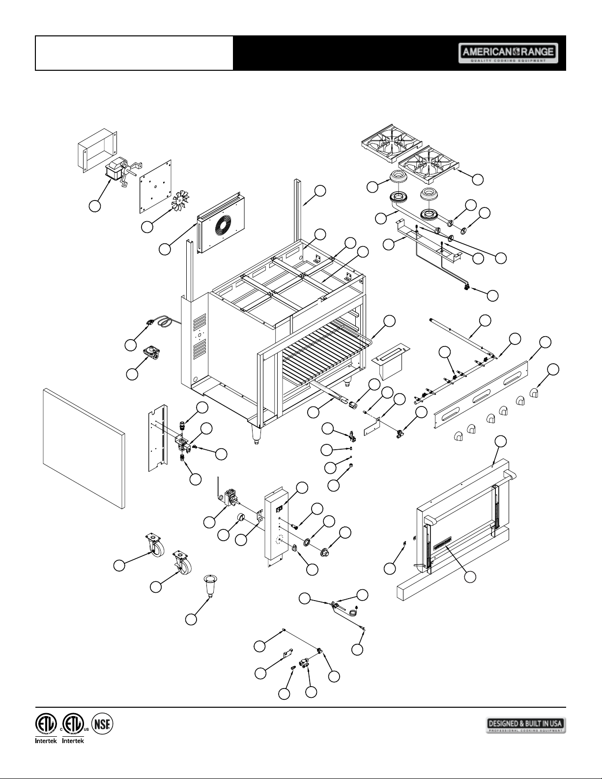
AR-6NV
58
54
1
53
2
3
57
56
52
55
51
50
49
48
47
44
45
4
44
5
43
42
41
40
33
34
6
7
32
31
35
36
39
8
30
29
6
27
28
26
9
5
0°
10
10
11
55
15
50
20
45
25
40
30
35
12
25
24
23
37
13
22
21
14
15
16
18
17
20
19
14
13592 Desmond St., Pacoima, CA 91331 818.897.0808 tel 888.753.9898 toll free www.americanrange.com
38
Page 19
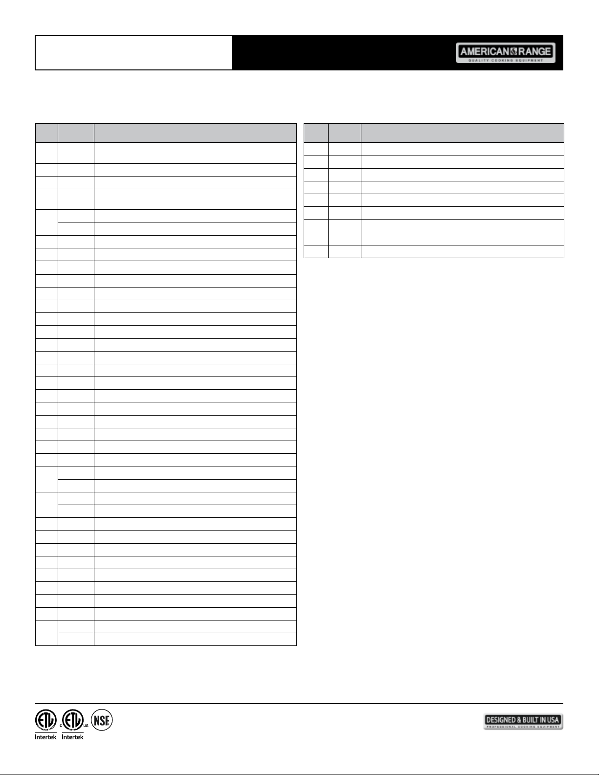
Owner’s Manual AR Series Ranges
AR-6NV
ITEM
ITEM
PART NO. DESCRIPTION
NO.
1 A91100
2 A91206 Fan, Blade Innovection Motor
4 A91202 Blower Bafe
5 A13100
A80110 Valve, Pressure Regulator 3/4" Natural Gas
6
A80011 Valve, Pressure Regulator 3/4" LP Gas
7 A28032 Elbow, 3/8" Compression Brass
8 A80101 Solenoid, Valve Safety Gas 115V
9 A29303 Elbow, 3/16CC - 1/8COMPC Brass
10 A28038 Elbow, Brass 3/8CC X 3/8 MNPT
11 A15037 Manifold Pipe (Convection) AR
12 A35014 Caster, 4" Swivel Plate Mount No Brake NSF AR, AGBU, ACB
13 A35015 Caster, 4" Swivel Plate Mount W/ Brake NSF AR, AGBU, ACB
14 A35001 Leg, 6" Cone 3" Adjustable Bullet Chrome Plated NSF
15 A11105 Thermostat, KXT Electric M/MSD
16 A60001 Timer, Cooking 60 Minute 10408 M/MSD, ARC
17 A99713 Bracket, KXT Thermostat M/MSD 1330 ARC
18 A32017 Knob, Timer M/MSD Series
19 A32005 Knob, Dial KXT Thermostat 10411 M/MSD Series, ARC/SAG
20 A32012 Bezel, BJ Thermostat
21 A10011 Light, Indicator 120V Red 12.7 10407 W/Wire Lead & Male Term
22 A10002 Switch, Rocker ON/OFF Innovection Oven
23 A28020 Nut, Reducer 1/4" - 3/16CC 10428
24 A28021 Sleeve, Ball 3/16" Tube Barrel
A1111 8 Orice, Bell .018 AR/AF Nat Gas
25
A1111 0 Orice, Bell .010 LPG Gas
A11104 Pilot, Nat Gas .018 5SL-2 AR/SAG
26
A11132 Pilot, LP Gas .010 5SL-2 AR/SAG
27 R14020 Burner, Bake Oven ARROB/ARRSB/AR Ranges
28 A44003 Nut, Speed, 6# Push Black 10601
30 A38000 Name Plate, American Range 8" Quality Commercial Chrome
32 A32001 Knob, Gas ON/OFF Glossy Black
34 A80109 Valve, Gas Manual ON/OFF UL 10419
36 A29301 Valve, Dual Gas Pilot 1/8 X 3/16C
37 A24000 Elbow, Orice Mixr 3/8C-3/8- 27 10442
38 A99713 Bracket, Orice Bracket ARC
A29000 Orice Hood, #39, 1/2" Brass 11039
39
A29007 Orice Hood, #53, 1/2" Brass
Motor, Innovection Fan Assembly ARR-Range Series / NV
Ranges
Cord, Power NEMA 5/15P SJT 16/3 6' Black Roj 5-1/2 GRN#10
Term
PART
NO.
NO.
40 A14049 Air Shutter, 1"
41 A31025 Rack, Oven AR6 26-3/8" X 20-7/8"
47 A14023 Burner, Lift Off Head Standard
48 A14024 Burner, Venturi Long Only 10447
51 A11200 Pilot, Tip Assembly Short New Front Open Burner AR Series
52 A11201 Pilot, Tip Assembly Long New Front Open Burner AR Series
53 A14037 Air Shutter, 2" 10464
54 A14025 Burner, Venturi Short Only 10446
55 A17000 Grate, Top 12" X 12" Cast Iron 10450-122
DESCRIPTION
15
13592 Desmond St., Pacoima, CA 91331 818.897.0808 tel 888.753.9898 toll free www.americanrange.com
Page 20
Owner’s Manual AR Series Ranges
!
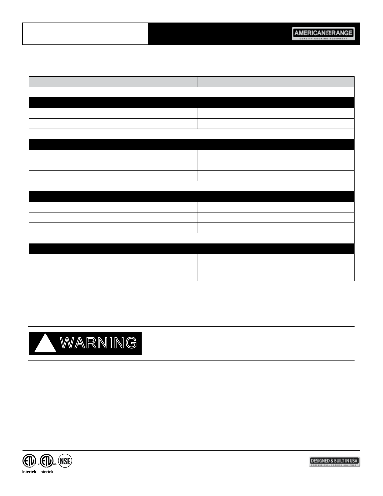
SUGGESTED ACTION
Unit is not connected to gas or electrical service Visually check unit is wired to gas or electrical service
Thermostat is set to very low temperature Set temperature to desired value
May not have been on long enough Unit preheats to 350ºF in about ten minutes
Thermostat may be defective Unit will require service
Too little gas pressure, dirty gas line Call for authorized service
Unit is not connected to electrical service Visually check unit is wired to electrical service
Power switch is off Move switch to ON position
Circuit breaker is tripped Reset the breaker, observe operation
Unit set to "standard" bake temperature
Thermostat out of calibration Unit will require service
WARNING
Set unit to "lower" convection bake temperature, operate for
shorter time
16
13592 Desmond St., Pacoima, CA 91331 818.897.0808 tel 888.753.9898 toll free www.americanrange.com
Page 21
Notes
13592 Desmond St., Pacoima, CA 91331 818.897.0808 tel 888.753.9898 toll free www.americanrange.com
Page 22
Notes
13592 Desmond St., Pacoima, CA 91331 818.897.0808 tel 888.753.9898 toll free www.americanrange.com
Page 23
Notes
13592 Desmond St., Pacoima, CA 91331 818.897.0808 tel 888.753.9898 toll free www.americanrange.com
Page 24

WARRANTY REQUIREMENT
R70028 120512
13592 Desmond Street, Pacoima, CA 91331
818.897.0808 tel 888.753.9898 toll free
818.897.1670 fax
www.americanrange.com
 Loading...