

American Megatrends X400 Hardware Manual
VPC6500 Series Vehicle PC Hardware Manual A.3 1
VPC6500
2-DIN Vehicle PC
Hardware Manual
Hardware Manual
November 2009, Ver. A.3
X400
X400

VPC6500 Series Vehicle PC Hardware Manual A.3 2
Copyright
This document by the original manufacturer is copyrighted © 2009, and all rights are
reserved. The original manufacturer reserves the right to make improvements to the
products described in this manual at any time without notice. No part of this manual may
be reproduced, copied, translated or transmi tted in any form or by any means wi thout the
prior written permission of the original manufacturer. Information provided in this manual
is intended to be accurate and reliable. However, the original manufacturer assumes no
responsibility for its use, nor for any infringements upon the rights of third parties that may
result from such use.
Copyright © 2009 by original manufacturer,
All rights reserved.
November 2009, Version A.3
Acknowledgments
AMI is a trademark of American Megatrends Inc. (AMI).
VIA is a trademark of VIA Technologies, Inc.
IBM, PC/AT, PS/2 and VGA are trademarks of International Business Machines
Corporation.
Intel, Pentium, Celeron, and MMX are registered trademarks of Intel Corporation.
Microsoft Windows
®
is a registered trademark of Microsoft Corp.
RTL is a trademark of Realtek Semi-Conductor Co., Ltd.
All other product names or trademarks are properties of their respective owners.
For more information, technical support and service about this VPC6500 V ehicle PC, please
contact your supplier where you have purchased from.
This manual is for VPC6500 series (Ver. A.3, November, 2009)
the X400
X400

VPC6500 Series Vehicle PC Hardware Manual A.3 3
Announcement
This manual is only written for the VPC6500 Vehicle PC series product with supporting
Windows based operating system use. The appropriate models for this user’s manual are in
the following list.
VPC6500 series
Limited Warranty
This product is warranted against manufacturing defects for the period of 1 year. During
one-year warranty period, defective parts will be repaired or replaced. There will be no
charge for labor or parts.
This warranty does not cover any failure resulting in loss to software, data, lost profits, lost
savings, any incidental damages or other economic consequential damages due to accident,
abuse, misuse, negligence and acts of God.
X400
X400 Series

VPC6500 Series Vehicle PC Hardware Manual A.3 4
Safety Notice
We make no warranties with respect to this documentation and disclaim any implied
warranties of merchantability and fitness for a particular purpose.
We shall not be liable for any error or for incidental or consequential damages in connection
with the furnishing, performance, or use of this documentation or the examples herein.
The information in this documentation is subject to change without notice.
1. This equipment should not be exposed to water or other liquids.
2. Do not cover the openings; the openings on the equipment are for air convection hence
protects the equipment from overheating.
3. Do not attempt to remove the cover of this equipment.
4. If any of the following situations arises, have the equipment checked by an authorized
service personnel:
• The USB connector is damaged.
• The power cord or connector is damaged.
• Liquid has penetrated into the equipment.
• The equipment has obvious sign of breakage.
Observe the following warnings when installing this unit.
1. Only a qualified professional may install or repair this unit, please contact your local
dealer for installation or repairing.
2. Use 12 VDC power supply only. This product is designed for operation with a negative
grounded 12 VDC battery system. Never operate this product with other battery
systems, especially a 24 VDC battery system.
3. Check for piping, gasoline tank, electric wiring, and other items before installing the
product.
4. Do not use safety-related vehicle components (fuel tank, brake, suspension, steering
wheel, pedals, airbag, etc.) for wiring or fixing the product or its accessories.
5. Installing the product on the air bag cover or in a location where it interferes with airbag
operation is prohibited.
6. In the case of installation to an airbag equipped car, confirm warnings and cautions of
the vehicle manufacturer before installation.
7. Without guidance of technicians, it is not allowed to replace the fuse of power supply.
Use of an improper fuse will damage the device or lead to smoke or fire.
8. Do not use the product where it may expose to water, moisture, or dust. Exposure of
the unit to water, moisture, or dust may lead to smoke, fire, or other damage to the

VPC6500 Series Vehicle PC Hardware Manual A.3 5
unit.
9. Do not cover the openings; the openings on the equipment are for ventilation hence
protects the equipment from overheating.
10. Never install the product in a location where it interferes with your field of vision.
11. Never have the power wire branched to supply other equipment with power.
12. After installation and wiring, you should check the normal oper atio n of other electrical
equipment.
13. Make sure the leads do not interfere with driving or getting in and out of the vehicle.
14. Isolate all exposed wires to prevent short circuiting.
Observe the following cautions when installing this unit.
1. Refer wiring and installation to qualified service personnel. Installation of this unit
requires special skills and experience. For maximum safety, have it installed by your
dealer . W e’re not liable for any problems resulting from your own installation of the unit.
2. Follow the instructions to install and wire the product. Not following the instructions to
properly install and wire the product could cause an accident or fire.
3. Take care not to damage the leads when wiring. Prevent them from getting caught in
the vehicle chassis, screws, and moving parts such as seat rails. Do not scratch, pull,
bend or twist the leads. Do not run them near heat sources or place heavy objects on
them. If leads must be run over sharp metal edges, protect the leads by winding them
with vinyl tape or similar protection.
4. Use the supplied or designated parts and appropriate tools to install the product. The
use of parts other than those supplied or designated may result in internal damage to
the unit. Faulty installation may lead to an accident, a malfunction or fire.
5. Do not install the product where it is exposed to strong vibrations or is unstable. Avoid
slanted or strongly curved surfaces for installation. If the installation is not stable, the
unit may fall down while driving and this can lead to an accident or injury.
6. Do not expose the unit to direct sunlight or excessive heat. Otherwise these will raise
the interior temperature of the unit, and it may lead to smok e, fire, or other damage to
the unit.
7. Do not block the air vent or the cooling plate of the unit. Blocking these parts will cause
the interior of the unit to overheat and will result in fire or other damage.
8. Wear gloves for safety. Make sure that wiring is completed before installation.
9. To prevent damage to the unit, do not connect the power connector until the whole
wiring is completed.
The user should bear in mind that in some areas there may be restrictions on how and
where this unit must be installed. Consult your dealer for further details.

VPC6500 Series Vehicle PC Hardware Manual A.3 6
Packing List
Before you begin installing your unit, please make sure that the following materials are
included in the packing:
• 1 x VPC6500 Vehicle PC main system
• 2 x CD (User Manual & Driver CD)
• 1 x Yellow card
• External cable kit with multi-lock connectors in 3 pieces (in a inner box)
If any of these items are missed or damaged, contact your distributor or sales
representative immediately.
Additional Information
Contact your distributor, sales representative, or customer service center for technical
support if you need additional assistance.
Please have the following information ready before you call:
• Product name and serial number
• Description of your peripheral attachments
• Description of your software (e.g. operating system, version, and application software…
etc.)
• A complete description of the problem
• The exact wording of any error messages
X400

VPC6500 Series Vehicle PC Hardware Manual A.3 7
Table of Content
Copyright ....................................................................................................2
Acknowledgments........................................................................................... 2
Announcement................................................................................................ 3
Limited Warranty ............................................................................................ 3
Safety Notice................................................................................................... 4
Packing List ....................................................................................................6
Additional Information.................................................................................... 6
Chapter 1 Introduction.................................................................................... 8
1.1 Introduction ........................................................................................ 8
1.2 VPC6500 features............................................................................... 8
1.2.1 Vehicle Use................................................................................8
1.2.2 Car Stereo ................................................................................8
1.2.3 MultiLock Connection .................................................................. 8
1.2.4 Windows O/S............................................................................. 9
1.2.5 Multimedia Graphic User's Interface..............................................9
1.2.6 Support GPS System (external device).......................................... 9
1.2.7 Wireless Network .......................................................................9
1.2.8 Bluetooth.................................................................................. 9
1.2.9 Smart Power .............................................................................9
1.3 General Specifications......................................................................... 10
1.3.1 Processor................................................................................ 10
1.3.2 Memory.................................................................................. 10
1.3.3 Storage (Optional) ...................................................................10
1.3.4 I/O Connector ......................................................................... 10
1.4 Front Panel..........................................................................................12
1.5 Rear Panel........................................................................................... 13
1.5.1 Connector A (Multi-40) .......................................................... 13
1.5.2 Connector B (Multi-24) .......................................................... 14
1.5.3 Connector C (Multi-16).......................................................... 16
1.6 Side view.............................................................................................16
Chapter 2 Installation for external device..................................................... 17
2.1 Introduction........................................................................................17
2.1.1 USB /SD card devices..................................................................... 17
2.1.2 Audio output................................................................................. 18
2.1.3 USB GPS installation ...................................................................... 18
2.1.4 Hand Braking............................................................................... 19
2.1.5 AUX Input ................................................................................... 20
2.1.6 CCD Camera ................................................................................ 20
2.1.7 Side Marker................................................................................. 21
Appendix A Pin Definition for MultiLock....................................................... 22
1. Multi-Lock Pin Assignment (Multi-40)................................................. 22
2. Multi-Lock Pin Assignment (Multi-24)................................................. 23
3. Multi-Lock Pin Assignment (Multi-16)................................................. 24
Appendix B Hard disk Assembly Instructions............................................... 25
X400

VPC6500 Series Vehicle PC Hardware Manual A.3 8
Chapter 1 Introduction
1.1 Introduction
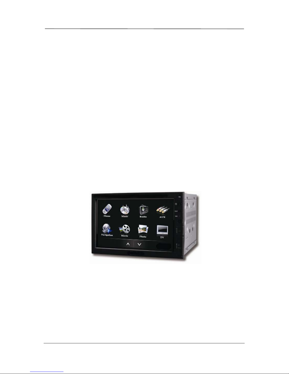
VPC6000 series Vehicle PC is the best 2-DIN Car PC solution in the market. The all-new
design improved 2-DIN features to be more friendly and easy-to-use. It’ s embedded with
car radio and built-in 5.1 channels amplifier with high-end sound stage simulation. The
front panel of the 2-DIN Car PC embeds a digital 6.95” LCD touch screen that provides 800
x 480 high resolution display that releases driver’s weariness.
Combined with multimedia entertainment system, it allows you using computing features
in car such as GPS navigation, WiFi/Bluetooth communication, Movie/ Music/ Phot o
playing, EQ control and smart power control…etc., by simply few touch clicks.
All combination in the unit fulfills car specification and it’s especially designed to meet
harsh environment such as sustaining extreme shock, vibration and high temperature
operation. VPC6500 brings you a vehicle infotainment computing runway whole the
driving.
The manual introduces hardware features and its operation instructions. Please read
carefully and the manual will guide you with more hardware description and installation.
1.2 VPC6500 features
1.2.1 Vehicle Use
• Vehicle-specific computer system
• 12 VDC power ready
• Suit to vehicle environment
• 2-DIN size with user friendly access buttons at front panel
1.2.2 Car Stereo
• 35W x 5 + Subwoofer output x 1
• FM and AM radio tuner embedded
• 18 FM/9 AM stations present
1.2.3 MultiLock Connection
• Standard vehicle use
• Secure data transferring
• Easy to connect and disconnect
The X400
The X400The X400
X400 Features

VPC6500 Series Vehicle PC Hardware Manual A.3 9
1.2.4 Windows O/S
• Microsoft Windows XP Embedded
• Support Windows bases application
1.2.5 Multimedia Graphic User's Interface
• Support media files playback
• Support software programs access
• Hands-free phone feature
• Music/Movie/Photo playback
• Flexible sound stage adjusting(EQ, audio output)
• GPS navigation
• WiFi/3G/Bluetooth communication
• Support digital TV
• Support web browser
• Intelligent system settings
1.2.6 Support GPS System (external device)
• USB GPS receiver supported (optional)
• Support Navigation software
1.2.7 Wireless Network
• Internet connection
• Web browse
1.2.8 Bluetooth
• Input device connectivity
• Support hands-free phone features
1.2.9 Smart Power
• Intelligent power control system
• Automatically power on/off with delayed time function
 Loading...