

Page 1
LED WALL PACK
Installation instructions for WP-R15 & WP-R30 Series
READ ALL OF THESE INSTALLATION INSTRUCTIONS BEFORE INSTALLING THE FIXTURE. FAILURE TO FOLLOW
INSTALLATION INSTRUCTIONS AND ALL APPLICABLE ELECTRICAL CODES WILL VOID THE PRODUCT WARRANTY.
WARNING:
These products may represent a possible shock or fire hazard if improperly installed or attached in any way.
Products should be installed in accordance with these instructions, current electrical codes and/or the current
National Electric Code (NEC).
WARNING:
Disconnect supply power from the source prior to installation. This product must be installed by a person familiar
with the construction and operation of the product and the hazards involved, and in accordance with current
electrical codes and/or the current National Electric Code (NEC). Consult a local licensed electrician if you are not
sure about the installation. To reduce potential of electric shock, fixture must be grounded. The electrical input
voltage of this product is 120-277V AC. The installer must determine whether power supply is in the range of
120-277V Ac at the luminaire before installation.
Do not mount or support these fixtures in a manner that can cut the outer jacket or damage the wire insulations.
Do not restrict fixture ventilation. Do not cover fixtures with insulation or any material that will impede air flow
around and heat dissipation of the fixtures.
APPLICATION / USE:
This product is suitable for use in wet locations and designed for surface mounting only.
installation where ambient temperatures do not exceed 104˚F (40˚C) during anticipated hours of fixture operation.
This xture is suitable for
INSTALLATION:
Disconnect supply power from the source prior to installation.
Installation requires T25 Security Torx Bit
1. Remove old fixture if applicable.
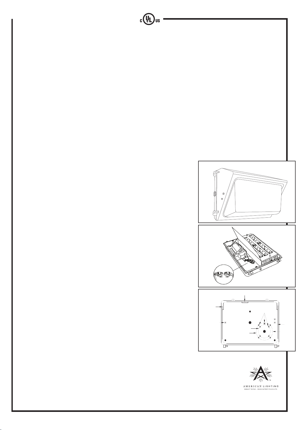
2. Open the lens assembly and remove the front cover. (Figure 1)
3. Unplug quick connect wires. (Figure 2)
4. Loosen two slotted head screws at each end of the LED heat sink module
and remove. (Figure 2)
5. Line up the back plate in desired location and mount securely. (Two gaskets
are provided for weather tight seal between template and junction box.)
6. Complete wiring to the power source and grounding wire.
7. Reinstall the LED heat sink
8. Remove protective cover from LED.
9. Replace front cover.
IMPORTANT:
To weather-proof your outdoor installation, seal all holes in xture housing
with silicone sealant.
MOUNTING:
The back plate has a cast-in drill and knock-out template to match
any standard recessed junction box, three 5/16” knockouts for mounting
holes (A) and three 1/2” NPS tapped holes (D) for surface conduit, photo
control. Refer to Figure 3 to locate these as needed:
A - 5/16” dia.
B - 9/16” dia.
C - Knockouts for #10 screw.
D - 1/2” NPS tapped holes.
Figure 1
Figure 2
Figure 3
D
GND
D
A
C
GR
31/4" OCT.BOX
A
B
4" OCT. BOX
D
GR
TEMPLATE
A
ADDITIONAL SAFETY MEASURES:
1. LEDs are not serviceable. Do not attempt to open the fixture or LED compartment.
2. LEDs are bright. Do not look directly into fixture.
3. Not intended for recess mounting in any type of installation.
4. Do not use with wall dimmers or in dimming circuits.
Note: These instructions do not cover all details or variations in equipment nor do they provide
for every possible situation during installation, operation or maintenance.
©2014 American Lighting
Denver, CO 80231 Made in China
RV-1435
www.americanlighting.com
 Loading...