

Page 1
Constant Voltage Drivers
Installation instructions for PS-25/60/100/150-12/24
BE SURE THAT SUPPLY POWER IS DISCONNECTED AT THE SOURCE BEFORE PROCEEDING!
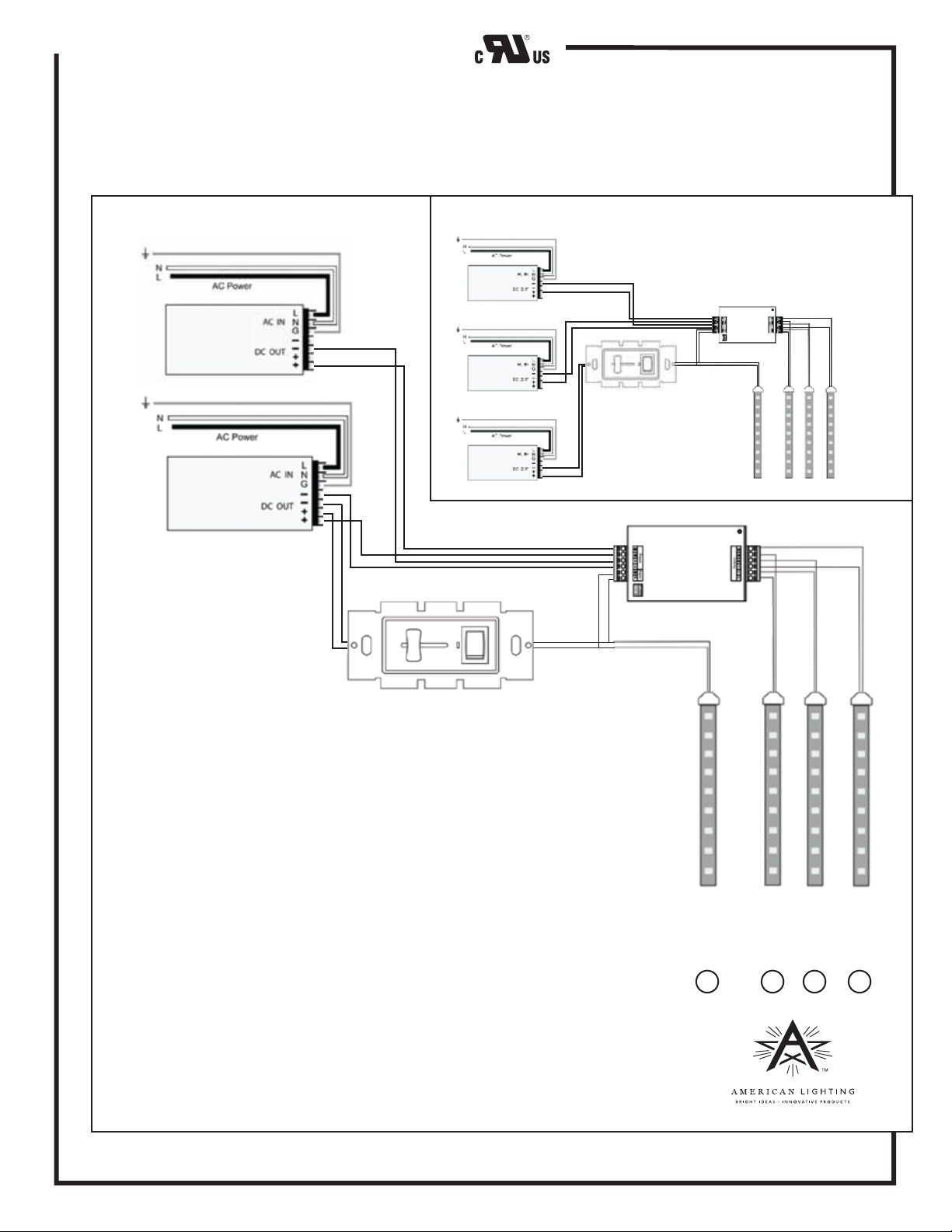
If the lighting load exceeds 72 watts for 12V loads, or 144 watts for 24V loads, a repeater (item number AL-3R-6A) can
be used in conjunction with the AL-PWM-6A dimmer and the constant voltage driver. See Figure 2 and installation
instructions for AL-3R-6A for more details about connecting multiple loads to one AL-PWM-6A dimmer.
When using a 24V system and three drivers, connect one max run up to
Figure 2
PS-150-24
PS-150-12
Driver
150 watts through the dimmer; then supply the repeater with power
directly as shown. The remaining three runs not to exceed 300
combined watts nor the maximum single run of the lighting product.
AL-3R-6A Repeater
PS-150-12
Driver
PS-150-24
PS-150-24
AL-PWM-6A
Dimmer
AL-PWM-6A Dimmer
AL-PWM-6A
Dimmer
AL-3R-6A
Repeater
72 watts of load may be attached to each of four runs in this 12V configuration when
two 150-watt drivers are used (part number PS-150-12).
144 watts of load may be attached to three runs in a 24V configuration when three
150-watt drivers are used (part number PS-150-24). See inset above. For 24V FlexForm,
one run of 144W max is directly powered by one driver. The two other runs of 144
watts will used a combined 288 watts and be powered by the two 150-watt driver
with the leftover 12 watts available for a short fourth run, if desired.
Note that the repeater and one of the 6A runs get their power from the secondary side
of the driver using the dual outputs (two positive and two negative terminals), In most
cases, when drivers with a single output (the 25-watt, 60-watt and 100-watt drivers)
are used, the repeater will not be necessary. In the case that multiple separate lower
wattage runs are attached to a 100-watt driver, for example, land the leads to both the
dimmer and repeater on the same terminals (matching polarity: red to positive and
black to negative) and do not exceed 100 watts of combined load, and no single run
can exceed the maximum run of the lighting product. See installation instructions and
cut sheets online for maximum runs for specific lighting products.
72 W
@12V
or
144W
@24V
1
72 W
72 W
@12V
@12V
or
144W
@24V
or
144W
@24V
2 3 4
72 W
@12V
or
12W
@24V
RV-1350
www.americanlighting.com
Page 2
Constant Voltage Drivers
Installation instructions for PS-25/60/100/150-12/24
WARNING:
should be installed in accordance with these instructions, current electrical codes and/or the current National Electric Code (NEC).
Install in a well-ventilated area free from explosive gases and vapors. Proper operation requires the free flow of air.
These products may represent a possible shock or fire hazard if improperly installed or attached in any way. Products
PLEASE READ THE FOLLOWING CAREFULLY BEFORE PROCEEDING!
CAUTION - To reduce risk of fire, electric shock or injury to persons:
1. ONLY A QUALIFIED ELECTRICIAN SHOULD INSTALL THIS HARDWIRE DEVICE.
2. BE SURE THAT SUPPLY POWER IS DISCONNECTED AT THE SOURCE BEFORE PROCEEDING!
3. DO NOT OPEN THE POWER SUPPLY OR ATTEMPT TO SERVICE - THIS COULD CREATE A SHOCK HAZARD
AND/OR DAMAGE THE DEVICE!
4. For all wire-to-wire connections, use UL Listed wire nuts.
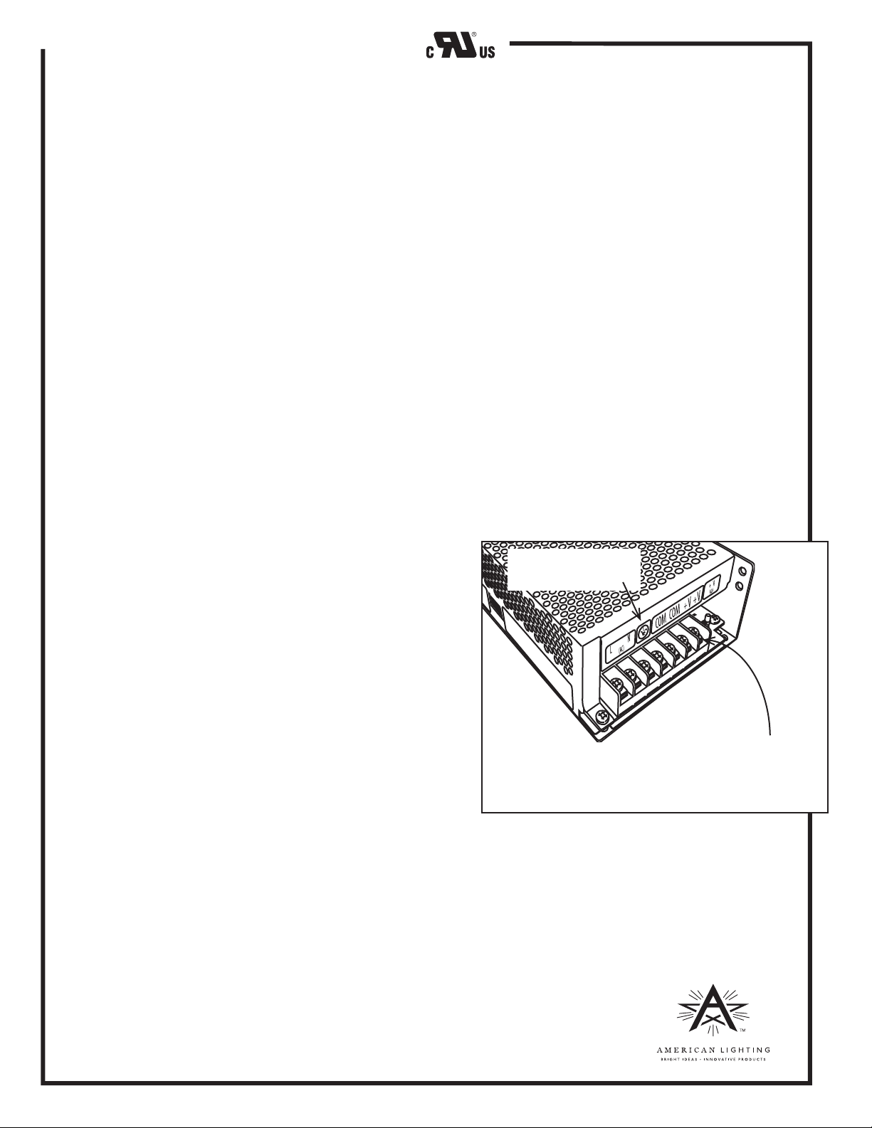
5. For all connections to the driver’s terminals, place conductor(s) between the metal plates, wrap it around terminal
screw clockwise so it stays in place as the terminal screw is firmly tightened for strain relief. See Figure 1.
6. The driver contains a single or double output. Make sure that the total connected load for does not exceed 100%
of its capacity in any case. PS-25-12 and PS-25-24 = 25 watts maximum; PS-60-12 and PS-25-24 = 60 watts maximum;
PS-100-12 and PS-100-24 = 100 watts maximum; PS-150-12 and PS-150-24 = 150 watts maximum.
7. The driver is dimmable with all dimmers designed for secondary connection to the power supply (those that
require a 12V and/or 24V input); and that provide pulse width modulation style of dimming. The factory
recommended dimmer is item number AL-PWM-6A for use with either 12V or 24V drivers, and corresponding
12V or 24V loads, up to 6 amps. (Note: 6 amps at 12V = 72 watts; 6 amps at 24V = 144 watts.)
8. For lighting loads that exceed 6 amps, factory recommended repeater (item number AL-3R-6A, sold separately)
must be used. See reverse side and the AL-3R-6A installation instructions for more information.
9. The components are protected for over load, over voltage and short circuit.
PRECAUTIONS BEFORE INSTALLING
1. This 100W and 150W power supplies have a Voltage Input
Selection Switch. Confirm the source voltage and be sure to set
the switch accordingly.
2. The operating temperature range is 0° to +50° for 100% loading;
-10° to +50° C for 80% loading; and 0° to +60° C for 60% loading.
3. Make sure that the source voltage is compatible and all lighting
loads to be attached are 12V or 24V constant voltage products.
4. Plan your lighting layout so that the connected load does not
exceed the driver’s capacity.
5. If the lighting load exceeds 72 watts for 12V loads, or 144 watts
for 24V loads, a repeater can be used in conjunction with the
AL-PWM-6A and the constant voltage driver. Please see reverse.
Be sure to gound driver in
accordance with NEC.
Place conductors between
metal plates and wrap around terminal screw
clockwise then firmly tighten with terminal screws..
INPUT & OUTPUT CONNECTIONS/GROUNDING
TO ENSURE SAFE OPERATION AND REDUCE THE POSSIBILITY OF INTERFERENCE, MAKE SURE THAT THE POWER SUPPLY
IS PROPERLY GROUNDED IN ACCORDANCE WITH NEC!
1. With the power turned off, route the supply wires to the L and N terminals and secure. See Figure 1.
2. Route the positive leads to the “+V” terminal(s) and negative leads to the “COM” or “–V” a terminal(s), respectively.
MOUNTING
1. When mounting, choose the best location on a vertical or horizontal surface that is capable of supporting
the weight of the driver.
2. Use the mounting slot and mounting hole located at opposing corners of its
base and suitable fasteners.
Figure 1
RV-1350
www.americanlighting.com
 Loading...