

Page 1
LED Contrax 120V Under Cabinet Light
Installation Instructions for LUC Series
WARNING: These products may represent a possible shock or re hazard if improperly
installed or attached in any way. Products should be installed in accordance with
these instructions, and with current electrical codes and/or the current National
Electric Code (NEC).
Warning: To avoid electric shock, disconnect power prior to installation.
Caution: Injury to persons and damage to the xture and/or mounting surface may
result if the xture is pulled from the surface. To reduce the likelihood of such injury
or damage, mount on a surface that is mechanically sound.
Use only a mild soap and/or water with soft cloth to clean the xture. Harsh chemicals will damage
the xture. Do not wipe the xture with a rough cloth that may scratch the nish or the lens.
Supply wires connection via housing knockouts:
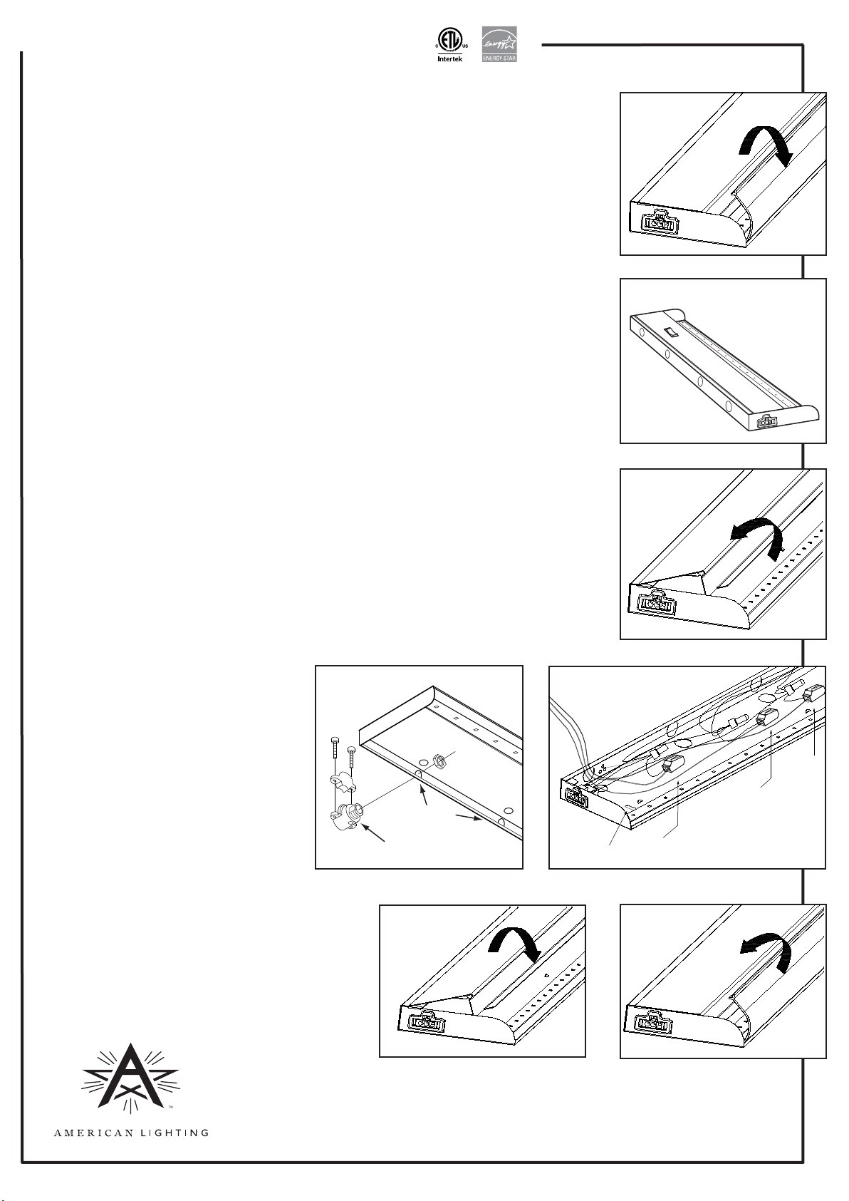
1. Remove the lens cover from the xture by lifting its back edge up gently and rotating it toward
the front of xture. See Figure 1.
2. Punch out whichever knockout is best suited for connection to 120V supply wires. Knockouts
are located along back and top of housing. See Figure 2.
3. Detach cover of wiring compartment by squeezing its front edge and rotating it backward in its
self-hinge. See Figure 3.
4. Install cable connnector and connect xture wires following National Electric Code and/or local
building code requirements. See Figure 4. AC supply should be 120V protected by circuit
breaker or fuse.
5. Use minimum 18AWG solid copper wires. Attach line voltage AC supply wires to xture lead
wires: Black to Black, White to White, Green or bare wire to Yellow/Green (Ground) inside the
xture. Secure each connection using the quick connector provided on the xture lead wire.
See Figure 5.
NOTE: If your system has no ground wire, you should consult a qualified electrician before
proceeding with the installation.
NOTE: Electric shock, overheating, low or no light output and shortened fixture life can result if
proper grounding is not done.
6. Replace the wiring compartment cover, securing lip under metal retaining tabs. See Figure 6.
NOTE: Be sure that the wires are not pinched or damaged by any part of the housing or cover.
Figure 1
Figure 2
16” unit shown.
See reverse for
other sizes.
Figure 3
Mounting xture:
NOTE: Lens cover must be o.
1. Determine desired location of xture and
mark locations of mounting holes (mark at
the small end of each keyhole slot).
2. Use a drill gun (or start holes with an awl)
and screw in mounting screws at these
locations, leaving 1/8” between head of
screw and mounting surface.
3. Slide xture over the mounting screws
using the keyhole slots to hold it in place,
then use a Philips screwdriver or driver bit
to tighten mounting screws and secure
xture to surface.
4. Replace the lens cover by tucking front lip
under front edge and pressing down rmly along
its entire length until it is secure. See Figure 7.
Multiple xtures may be interconnected with linking
cables (3” cable included with xture, other sizes sold
separately). SEE REVERSE FOR CONNECTING MULTIPLE
FIXTURES TOGETHER.
SEE REVERSE FOR PLUG-IN INSTALLATION INSTRUCTIONS.
Figure 4
Cable connector
Figure 5
Knockouts
Keyhole slot
Figure 6 Figure 7
Yellow/Green wire
(G)
White wire
(N)
Black
wire
(L)
RV1303 www.americanlighting.com
Page 2
LED Contrax 120V Under Cabinet Light
Installation Instructions for LUC Series
For supply wires connection (hardwire instructions) via housing knockouts, see reverse.
Plug-in installation:
NOTE: Power cords are sold separately from xtures. Plug-in installation requires purchase of LUC Series grounded power
cord (item number LUC-PC6-BK or LUC-PC6-WH).
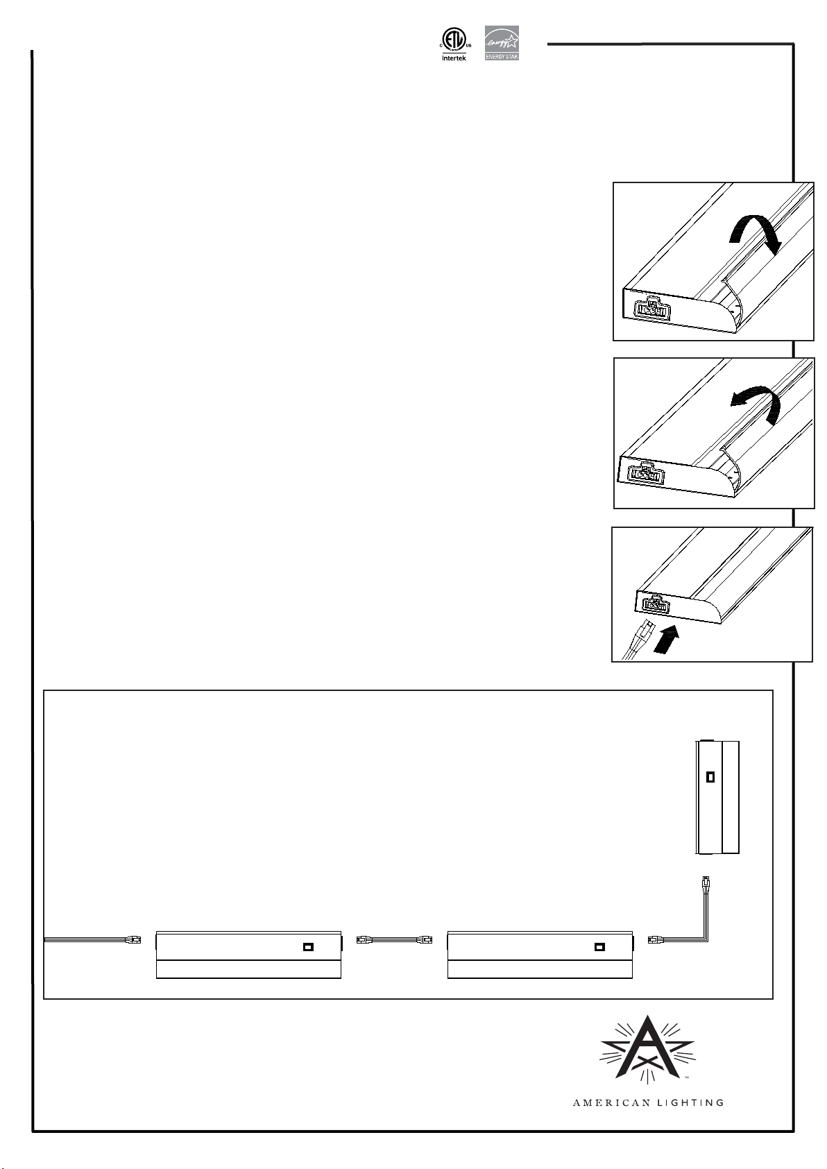
1. Remove the lens cover from the xture by lifting its back edge up gently and rotating it toward
the front of xture. See Figure 8.
2. Determine desired location of xture and mark locations of mounting holes (mark at the small
end of each keyhole slot).
3. Use a drill gun (or start holes with an awl) and screw in mounting screws at these locations,
leaving 1/8” between head of screw and mounting surface.
4. Slide xture over the mounting screws using the keyhole slots to hold it in place, then use a
Philips screwdriver or driver bit to tighten mounting screws and secure xture to surface.
5. Replace the lens cover by tucking front lip under front edge and pressing down rmly along its
entire length until it is secure. See Figure 9.
6. Insert the power cord into one of the end ports of the xture. The xture can be powered from
either end. See Figure 10.
7. Plug other end of power cord into 120V AC receptacle.
Additional Safety Measures:
1. Do not look directly at LED light source.
2. Do not touch the LEDs.
3. To avoid electrical shock, do not turn on xture with missing or damaged lens.
4. There are no serviceable parts inside LED module.
5. The power cord and extension cables are not serviceable. Inspect cords periodically.
Replace if damaged in any way.
6. WARNING! CAUTION - RISK OF FIRE: Keep xtures away from curtains and other
combustible materials.
7. Suitable for indoor dry locations only.
8. This product is suitable for use in dimming circuits. For best results (5-100% lighting
control), use Lutron LG-603PG, CTCL-153PDH or CVCL-153PD type dimmers
(www.lutron.com).
Figure 8
Figure 9
Figure 10
WARNING! CAUTION - RISK OF FIRE: Keep xtures away
from curtains and other combustible materials.
Suitable for indoor dry locations only.
Connecting Multiple Fixtures Together:
Plug ends of linking extension into end power connection ports on adjacent xtures.
Up to 50 xtures can be connected with one power cord or to one hardwired xture.
Each xture includes a 3” linking extension. Fixtures can be installed so they are powered from
an adjacent xture by using the 3” linking extension included with the xture; or 6”, 12” or 24”
linking extensions sold separately.
For 6”, 12” or 24” length linking extensions, order item numbers LUC-EX6-XX, LUC-EX12-XX
or LUC-EX24-XX, respectively. (XX denotes cord color options where BK = Black and WH = White.)
The xture can be
powered from either end
RV1303 www.americanlighting.com
 Loading...