

Page 1
LED Pendant Series Light Module
tion inst
WARNING: These products may represent a possible shock or re hazard if
improperly installed or attached in any way. Products should be installed in
accordance with these instructions, and with current electrical codes and/or
the current National Electric Code (NEC). This light module is intended to be
installed only by qualied personnel.
WARNING: To avoid electric shock, disconnect power at source
prior to installation.
Save these instructions.
Alteration of the xture or accessories will void the warranty.
For indoor installations only. Do not use where ambient temperature
exceeds 104°F (40°C); suitable for use in environments with 0-80% humidity.
Using this product in environments outside of these ranges will impact LED
life negatively.
For 120V, 60Hz input power applications only. Fixtures consume 7.5 watts
per module. Unpack the xture and inspect for any damage. If there is any
damage to the pendant cord, LED lens or wire inside canopy, do not install.
ruInstalla
ctions for PEN Series Light Module
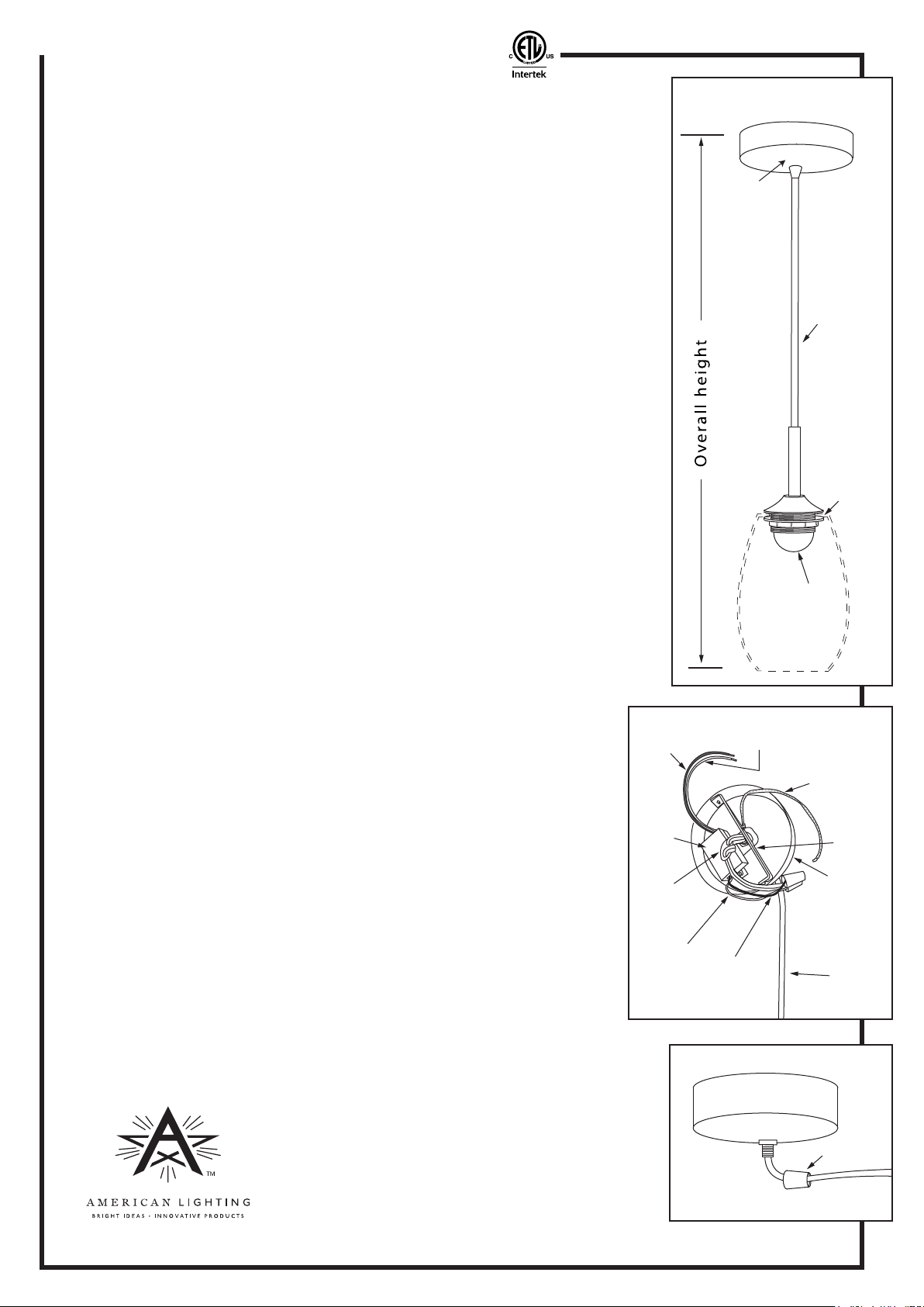
Figure 1
Canopy
Pendant cord
Note: Glass shade is sold separately.
DETERMINE OVERALL LENGTH OF PENDANT LIGHT: (See Figure 1)
G
enerally, the bottom of the pendant glass would be 24”-30” above a dining
table or eating counter, but perhaps more clearance may be needed over an
island. Consider surface height, pendant glass height and any clearance
issue(s) when determining overall height.
ADJUSTMENT OF PENDANT CORD: (See Figures 2 and 3)
1. Remove two retaining screws on side of canopy and set aside. Remove
mounting bracket and set aside. See Figure 2.
2. Loosen plastic nut on canopy. See Figure 3.
3. Adjust pendant cord to appropriate length by pulling up through the
canopy to achieve overall height per Figure 1.
4. Adjust position of strain relief ring by loosening pendant cord and moving
ring to location at side of driver. Pull any additional pendant cord through
ring to take up any slack.
5. Screw plastic nut back onto canopy and retighten to secure pendant cord.
CONTINUED ON REVERSE
ADDITIONAL SAFETY MEASURES:
1. To avoid electrical shock, do not turn on fixture with missing or damaged lens.
2. There are no serviceable parts inside LED module.
3. Suitable for indoor dry locations only.
4. This product is suitable for use in dimming circuits. Dimmable with most
incandescent, low voltage electronic and low voltage magnetic dimmers.
The use of chemicals or solvents may degrade the housing nish or its
protective coating. Use only a mild soap and/or slightly damp soft cloth
to clean the xture. Harsh chemicals will damage the lens and/or xture.
Do not wipe the xture with a rough cloth that may scratch the nish or the lens.
Black
wire
LED
driver
Strain
relief
ring
Red
Wire
Top View
Black
Wire
White
wire
Lock nut
Frosted
LED lens
Glass shade is
sold separately
Figure 2
Yellow/Green
ground wire
Mounting
bracket
Canopy
Pendant
cord to
lighting
module
Figure 3
Denver, CO 80231 • www.americanlighting.com
Canopy
Side View
American Lighting, Inc. RV1326 Page 1 of 2
© 2013
Plastic nut
Pendant cord
Page 2
LED Pendant Series Light Module
tion inst
WARNING: To avoid electric shock, disconnect power at source prior to installation.
ruInstalla
ctions for PEN Series Light Module
CONTINUED FROM REVERSE
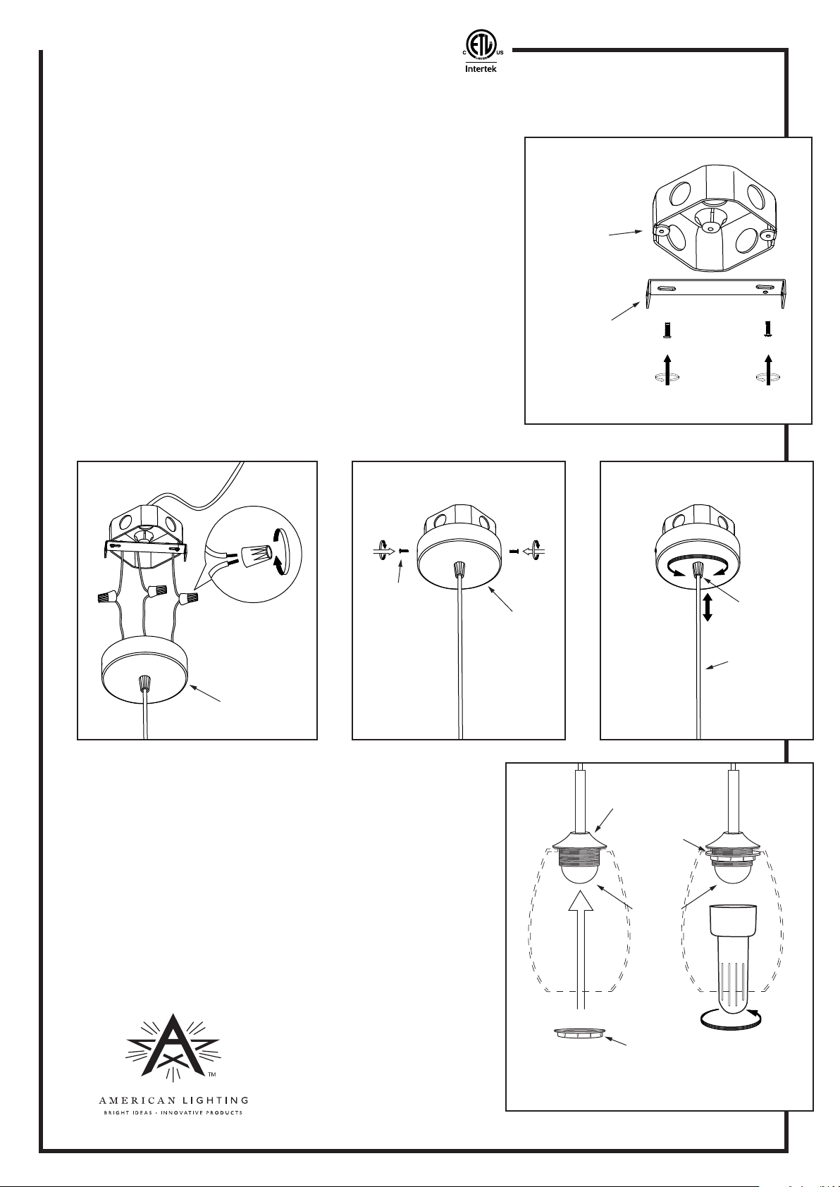
INSTALLATION INSTRUCTIONS: (See Figures 4-6)
1. Remove existing fixture if applicable.
2. Secure the mounting bracket to the existing junction box. See
Figure 4.
3.
Strip back jacket on supply wires 3/8“ and use UL Listed wire
connectors to connect wires (Black to Black/Hot, White to
White/Neutral and Yellow/Green stripe [Ground] to bare
wire). See Figure 5.
4. Bundle the extra pendant cord into canopy and/or junction box.
5. Align holes on side of canopy with mounting bracket holes and
attach canopy to mounting bracket using the retaining screws
previously set aside. See Figure 6.
6. Loosen the plastic nut and make any small adjustments to
overall length, if desired, and re-tighten the nut to secure pendant cord. See Figure 7.
Figure 5 Figure 6 Figure 7
junction
box
mounting
bracket
Figure 4
Retaining
screw
Canopy
GLASS INSTALLATION INSTRUCTIONS:
1.
Unscrew round lock nut from pendant module. Set it aside. See
Figure 8.
2. Lift glass shade over frosted LED lens. Slide lock nut over
frosted LED lens and screw it back into place from the underside
of the glass shade.
3. Optionally, you may use the lock nut tightening tool (plastic
wrench provided with pendant module) to tighten lock nut into
place and secure glass shade. See Figure 8.
CAUTION! Do not over-tighten locking nut!
Overtightening risks breaking glass shade!
4. Carefully straighten pendant cord with glass shade attached.
Verify equipment is secure.
Plastic nut
Canopy
Pendant cord
Figure 8
Pendant
module
Lock nut
Frosted
LED lens
Denver, CO 80231 • www.americanlighting.com
Lock nut
American Lighting, Inc. RV1326 Page 2 of 2
2013
Optional: Use
plastic wrench to
gently tighten lock nut
 Loading...