

Page 1
4” E-Pro LED Recessed Downlight
Installation instructions for EP4 Series
These products may represent a possible shock or fire hazard if improperly installed or attached in
WARNING:
any way. Products should be installed in accordance with these instructions, current electrical codes and/or
the current National Electric Code (NEC).
CAUTION - To reduce risk of fire, electric shock or injury to persons:
1. Make sure that the electrical power to the fixture is disconnected prior to any installation or retrofit.
2. This light is intended for indoor use only.
3. Use with 4” recessed cans (recessed housings) only. Do not attempt to alter for other sizes or purposes.
WARNING: Risk of re or electric shock. Install these kits only in 4” recessed housings. Conrm this before installation
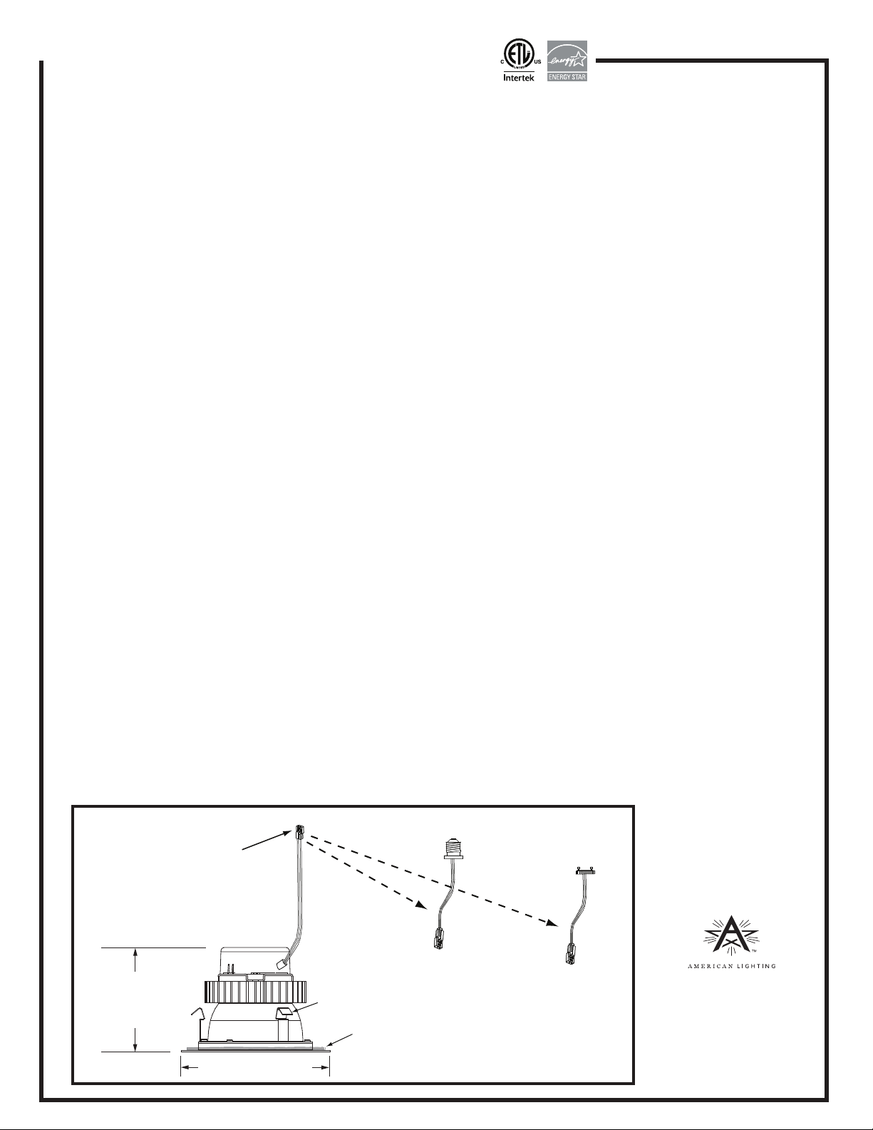
by checking the interior of the housing for a manufacturer’s part number and specications; or measure the diameter of the housing. The recessed housing must have a minimum measured inside diameter (opening) of 4”; maximum diameter 4-5/8”; minimum clearance of 3-7/8”. See Figure 1.
Do not make or alter any open holes in a wiring enclosure, nor in any electrical components during kit installation!
WARNING: Risk of re or electric shock. Kit installation requires knowledge of recessed lighting luminaires electrical
systems. If not qualied, do not attempt installation. Contact a qualied electrician.
Do not use these products in luminaires located where elevated ambient temperatures exist.
WARNING: Risk of re or electric shock. The electrical rating of this product is 120V AC. The installer must determine
whether power supply is 120V AC at the luminaire before installation.
WARNING: To prevent wiring damage or abrason, do not expose wiring to edges of sheet metal or other sharp
objects.
THIS PRODUCT MUST BE INSTALLED IN ACCORDANCE WITH THE APPLICABLE INSTALLATION CODE BY A PERSON
FAMILIAR WITH THE CONSTRUCTION AND OPERATION OF THE PRODUCT AND THE HAZARDS INVOLVED.
THE RETROFIT ASSEMBLY IS ACCEPTED AS A COMPONENT OF A FLUORESCENT LUMINAIRE WHERE THE SUITABILITY
OF THE COMBINATION SHALL BE DETERMINED BY CSA OR AUTHORITIES HAVING JURISDICTION.
Each xture includes an attached lead wire with a 120V socket adaptor (for use with either a GU24 or E26 adaptor);
an E26 adaptor; an insulating foam ring and a pair of attached torsion clips. See Figure 1.
FUTURE LAMP REPLACEMENT: Model EP4-E26-XX-YY (4” E-Pro LED Downlight is available from American Lighting, Inc.
Contact 800-880-1180 or visit www.americanlighting.com to find a local distributor.
Figure 1
120V plastic connector
for use with either a
GU24 or E26 adaptor
3-3/8” (85mm) height
Up to 1/2” additional
clearance required
for adaptor
5” (128mm) diameter
Torsion clips
Insulating foam ring
E26 adaptor
(included with fixture)
GU24 adaptor
(item number
AL-GU24,
sold separately)
www.americanlighting.com
©2012 American Lighting, Inc.
Denver, CO 80231
RV-1333
Page 1 of 2
Page 2
4” E-Pro LED Recessed Downlight
Installation instructions for EP4 Series
CAUTION: Always make sure power to the fixture is disconnected before beginning removal of
existing lamp and/or trim, or before beginning retrofit installation. Failure to do so can cause
electric shock, which can result in injury or death.
RETROFIT INSTALLATION
1. Confirm the LED trim is compatible with the recessed housing as outlined on reverse.
2. Remove existing lamp from existing recessed housing.
3. Remove existing trim from existing recessed housing.
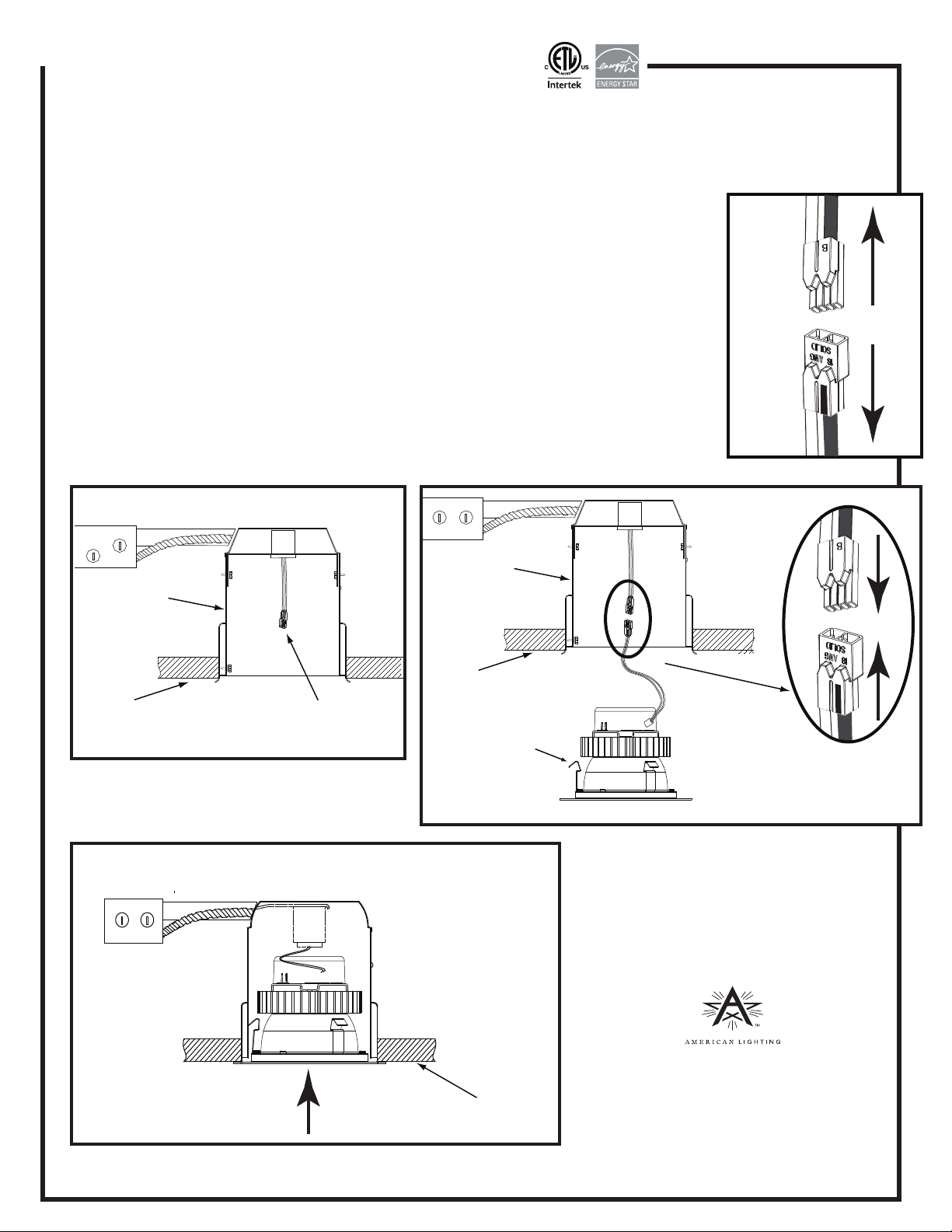
4. Detach E26 socket adaptor from LED fixture by grasping plastic connectors firmly
and pulling apart. Do not grasp wires to pull connectors apart. See Figure 2.
5. Screw E26 socket adaptor into existing E26 socket at the back of the housing; or push
and twist GU24 socket adaptor into existing GU24 socket at back of housing. See Figure 3.
6. Insert male connector pins into female con
nector and press firmly together until fully
seated. See Figure 4.
7. Anchor fixture to recessed can, aligning torsion clips with interior wall of can. See Figure 5.
Figure 3
Recessed
Recessed
housing
housing
Figure 2
Figure 4
Ceiling
E26 or GU24
socket adaptor
NEW CONSTRUCTION INSTALLATION
Follow step 1, then steps 4-7 above.
Figure 5
EP4 Installed
Ceiling
Torsion clips
Ceiling
Insert male connector pins
into female connector and
press firmly until fully seated
www.americanlighting.com
©2012 American Lighting, Inc.
Denver, CO 80231
RV-1333
Page 2 of 2
 Loading...