

Page 1
LED Clear Flex V2 -Single Color
Installation intructions for CFX2V2 Series
WARNING: These products may represent a possible shock or fire hazard if improperly installed or attached in any way. Products
should be installed in accordance with these instructions, current electrical codes and/or the current National Electric Code
(NEC).
PLEASE READ THESE INSTRUCTIONS CAREFULLY BEFORE INSTALLATION. SAVE THESE INSTRUCTIONS.
IMPORTANT INSTALLATION INFORMATION
• Before beginning installation or maintenance, be sure electricity is switched o at the source.
• Note: All joints end caps and connections must be sealed correctly to achieve IP68!
• A heat gun is required for installation (not supplied).
• Ensure that polarity and all connections are correct before turning on power.
Notes: The power consumption for CFX2V2 is 3.6 watts/foot (12 watts/meter). The maximum run is 16.4 feet
(20 meters). The cutting increment is every 3.9” (100mm). The minimum bending radius is 11/16“ (15mm).
THIS KIT INCLUDES THE FOLLOWING COMPONENTS:
(3) Power connection kits (CFX2V2-CONKIT-NP); one is pre-attached to reel
(1) 16’ 4-3/4”(5m) reel of Clear Flex2, CFX2V2 Series (1) Splice connection kit (CFX2V2-SPL)
(16) Mounting clips and screws (CFX2V2-CLIPS) (1) 20mL bottle of glue (CFX-GLUE)
ACCESSORIES AVAILABLE, SOLD SEPARATELY:
• Extension cables (jumpers) in .5, 1, 6 and 10 foot lengths
(CFX2V2-JUMP.5, CFX2V2-JUMP1, CFX2V2-JUMP6 and CFX2V2-JUMP10)
• Power connection kit (CFX2V2-CONKIT-NP) • Splice connection kit (CFX2V2-SPL)
• 20mL bottle of glue (CFX-GLUE) • Set of 3 end caps (CFX2V2-ENDS)
• Set of 16 mounting clips (CFX2-CLIPS) • Aluminum mounting channel, 3.28’(CFX2V2-CHAN-1M)
OTHER SAFETY PRECAUTIONS:
• Do not operate this product in environments where ambient temperatures exceed 113˚F (45˚) or drop
below 41˚F (5˚C).
• Do not cover this product as the covering may cause it to overheat, melt or ignite.
• Do ot operate LED rope light while it is tightly coiled.
• Do not route cord or light through walls, ceiling, doors, windows or any similar part of building structure.
• Do not install in vertical orientation, twisted, or bending along the short side. See bottom of page 2.
• Secure this exible light using only mounting clips provided or factory recommended mounting track
(CFX2V2-CHAN-1M, sold separately).
• Do not secure this product or its cord with staples, nails, or like means that may damage the insulation.
• Do not use if there is any damage to the PVC housing or power cord insulation. Inspect periodically.
• Do not install on gates or doors, where subject to continuous exing.
• Do not install in tanks or enclosures of any kind.
• Follow instructions carefully when splicing LED rope sections or attaching power cords. Ensure that all
connections, including the end cap on the last segment, are properly installed with sealant and shrink tube
to preclude the entrance of water.
• Risk of re. Do not alter power pins. Use only factory-recommended power connectors and accessories.
• Clear Flex2 can only be cut at intervals indicated by the cutting marks printed on the side of PVC housing.
• Failure to cut at a cut mark will result in a loss of light. Before making any cuts or attaching any power cords
or jumpers, be sure power source is disconnected!
• This product is designed for use by a qualied installer.
• For decorative use only. Not to be used by children as a toy. Keep out of reach of small children.
WARNING - When using outdoor portable lighting products, basic safety precautions should always be
followed to reduce the risk of re, electric shock and personal injury, including the following:
CAUTION - To reduce risk of re, electric shock or injury to persons be sure to follow power supply’s
instructions including:
1. Use silicone and shrink tube at all power connections including end cap when using outdoors.
2. Use Ground Fault Circuit Interrupter (GFCI) protection on the circuit(s) or outlet(s) when using outdoors.
3. Use only UL approved outdoor extension cords, such as type SW, SOW, STW, STOW, SJW,
SJOW, SJTW or SJTOW. This designation is marked on the jacket of the extension cord.
RV1316 www.americanlighting.com
Page 2
LED Clear Flex V2 -Single Color
Installation intructions for CFX2V2 Series
INSTALLATION INSTRUCTIONS
1. Disconnect power at source before installation or maintenance.
2. Clear Flex2 requires DC 24V LED Power Supply! Do not connect to 120V AC power!
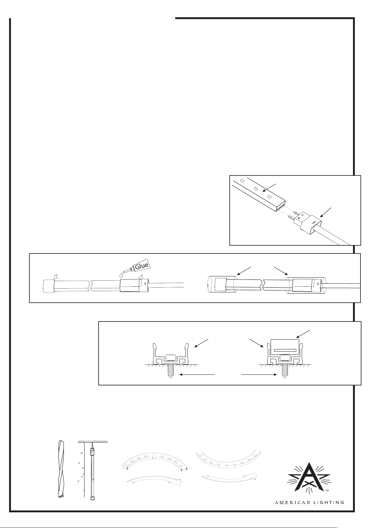
3. To connect power connection kit to the Clear Flex2:
• Push the pins of the connector kit into the end of the Clear Flex2 making sure that the two prongs make full
contact with both of the internal conductors. See Figure 1.
Note: Polarity is marked “ + - ” on the connector kit and Clear Flex2. If polarity is reversed, the LEDs will not be
damaged. They simply will not operate.
• Apply glue into the heat shrink tube, and slide the shrink tube over the joint where the power cord and Clear
Flex2 meet. See Figure 2.
• Use a heat gun to gently apply heat until the shrink tube shrinks in place over the assembly.
4. To connect the end cap to the Clear Flex2:
• Apply glue into the end cap and push the Clear Flex2 into the cap, until it is fully seated.
• Apply glue into the heat shrink tube and slide the shrink tube over the joint where the end cap and the Clear
Flex2 meet.
• Use a heat gun to gently apply heat until the shrink tube shrinks in place over the assembly.
5. To connect two sections of Clear Flex2 together using a splice connector:
• Slide the heat shrink tube onto one of the pieces of Clear Flex2 to be joined.
• Insert the connector pins into this piece of Clear Flex2 being sure to
make full contact with each of the internal conductors.
• Align the second piece of Clear Flex2 and push onto the connector
pins, making full contact with each internal conductor.
• Apply glue around the surface of both ends of the Clear Flex2
pieces and slide the heat shrink tube over the joint.
• Use a heat gun to gently apply heat until the shrink tube shrinks in
place over the assembly. Note: The glue must make contact with all
surfaces of the joints. Be sure that the heat shrink tube completely
covers each of the joints to maintain IP65 rating.
Figure 1
Lighted surface
Connector kit
Figure 2
6. Clear Flex2 can be mounted using the mounting clips or using aluminum mounting channel as shown below.
See Figure 3.
Figure 3
7. Clear Flex2 can be cut every six LEDs (approximately every 3.9“). Cut squarely on the cutting mark. Cutting
anywhere else will result in loss of 3.9” of light (one series parallel section).
8. Connect Clear Flex2 to a 24V DC power supply, ensuring the polarity is correct (red to positive and black to
negative). Do not apply 120V AC power to Clear Flex2! Please also refer to the power supply’s instructions.
DO NOT TWIST, MOUNT VERTICALLY OR BEND ALONG SHORT SIDE:
Aluminum Channel
Screw
Heat shrink tube
Light surface
×
RV1316 www.americanlighting.com
×
×
×
 Loading...