

Page 1
IP16 INSTALLATION
NOTE: The position of the indicator post target must be set to coincide with the position of the valve. Failure to coordinate these
positions can result in inaccurate valve position indication or may render the valve position indication mechanism inoperable.
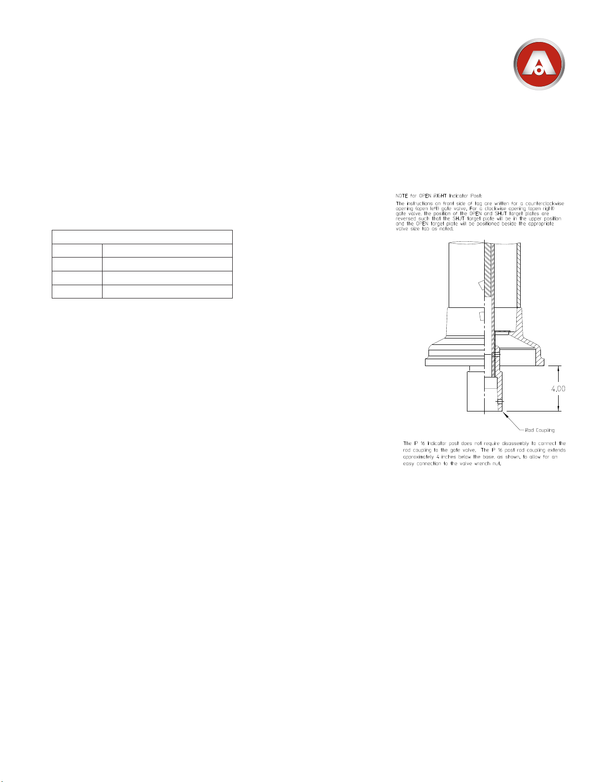
The installation instructions below are written for a counterclockwise opening (open-left) gate valve. For a clockwise opening
(open-right) gate valve, the position of the “OPEN” and “SHUT” target plates are reversed such that the “SHUT” target plate will
be on the upper position and the “OPEN” target plate will be positioned beside the appropriate valve size tab as noted below.
Installation
The IP16 Indicator Post is factory-set with the “SHUT” Target Plate (IP-16-
1.
15) positioned as shown in the following table. When the Indicator Post is
mounted to the sizes listed in the table, skip down to instruction item 6.
IP16 Model Post Indicator Valve Size
When the Indicator Post is mounted to valve sizes other than those listed
in the table, follow the instructions below to remove the Head (IP-16-5) and
adjust the “SHUT” Target Plate (IP-16-15).
2.
To remove the head (IP-16-5), remove the Operating Wrench (IP-16-2), the
eyebolt (IP-16-3) and hex-head bolt (IP-16-9). Using a screwdriver, remove
one of the Screws (IP-16-17), located on top of the head (IP-16-5) and adjacent to the Operating Stem Nut (IP-16-1) and loosen the other screw (IP16-17). Spread the Stung Box clips (IP-16-23) apart. Note the overlapping arrangement of the clips for proper re-assembly. Gently lift the Head
(IP-16-5) to remove.
Locate the desired gate valve size tab on the side of the Target Carrier (IP-
3.
16-24), loosen the “SHUT” target plate fastening Screws (IP-16-17) and
reposition both “SHUT” Target Plates (IP-16-15) to the center of the desired
gate valve size tab and then re-tighten the Screws. Do not rotate the Target
Carrier Nut (IP-16-13) on the Operating Stem Nut (IP-16-1) to maintain the
factory-set position of Target Carrier (IP-16-24).
4.
Apply lubricating oil to the O-ring (IP-16-33) at the top of the Operating Stem Nut (IP-16-1). Place the Head (IP-16-5)
onto the post and re-assemble the Stung Box clips (IP-16-23) into the groove on the Operating Stem Nut (IP-16-5)
and tighten the Screws (IP-16-17). Fasten the Head (IP-16-5) to the Upper Barrel (IP-16-29) by threading and tightening the Eye Bolt (IP-16-3) and Hex Head Bolt (IP-16-9). Make sure the Eye Bolt (IP-16-3) is fastened in the bolt hole 90
degrees from the Target Plate sight windows.“OPEN” targets centered in the sight windows of the head. If not, turn the
operating nut until the “OPEN” targets are centered in the sight window.
5.
Verify that the “OPEN” Target Plates (IP-16-14) are centered in the sight windows of the Head (IP-16-5). If they are
not, turn the Operating Stem Nut (IP-16-1) until the “OPEN” Target Plates (IP-16-14) are centered in the sight window.
6.
Open the gate valve fully to match the OPEN indication.
7.
Pin the Rod Coupling (IP-16-11) of the IP16 Indicator Post to the 2” wrench nut on the gate valve using the Cotter Pin
(IP-16-12) provided.
8.
Mount the IP16 Indicator Post to the post indicator valve (PIV) plate on the gate valve.
9.
Close the gate valve completely to verify that the “SHUT” Target Plate (IP-16-15) displays properly in the sight window.
10.
Adjust the IP16 Indicator Post height to accommodate the trench depth by loosening the square head Set Screws (IP-
16-8) located below the BURY line on the Upper Barrel (IP-16-29). Once the Indicator Post is adjusted to the proper
length, tighten the Set Screws on the Upper Barrel (IP-16-29) to secure the barrels together.
Factory-Set Target Positions
A 6-inch
B 16-inch
C 24-inch
8013668
AMERICAN Flow Control
Page 4B-8
IP16 Indicator Post
 Loading...