

Page 1
© Copyright 2006, American Fibertek, Inc. 1218JD
Instruction Manual
With Diagnostic Interface
SR-20D
Sub Rack
Page 2
Specifications SR-20D
Plug-in Cards SR-20D 13
Size 19” x 5 ¼” x 9”
Weight 4 ½ lbs.
2
Page 3

INSTALLATION AND OPERATION INSTRUCTIONS
INTRODUCTION
Thank you for purchasing your American Fibertek SR-20D sub-rack with diagnostic interface.
Please take a few minutes to read these installation instructions in order to obtain the maximum
performance from this product.
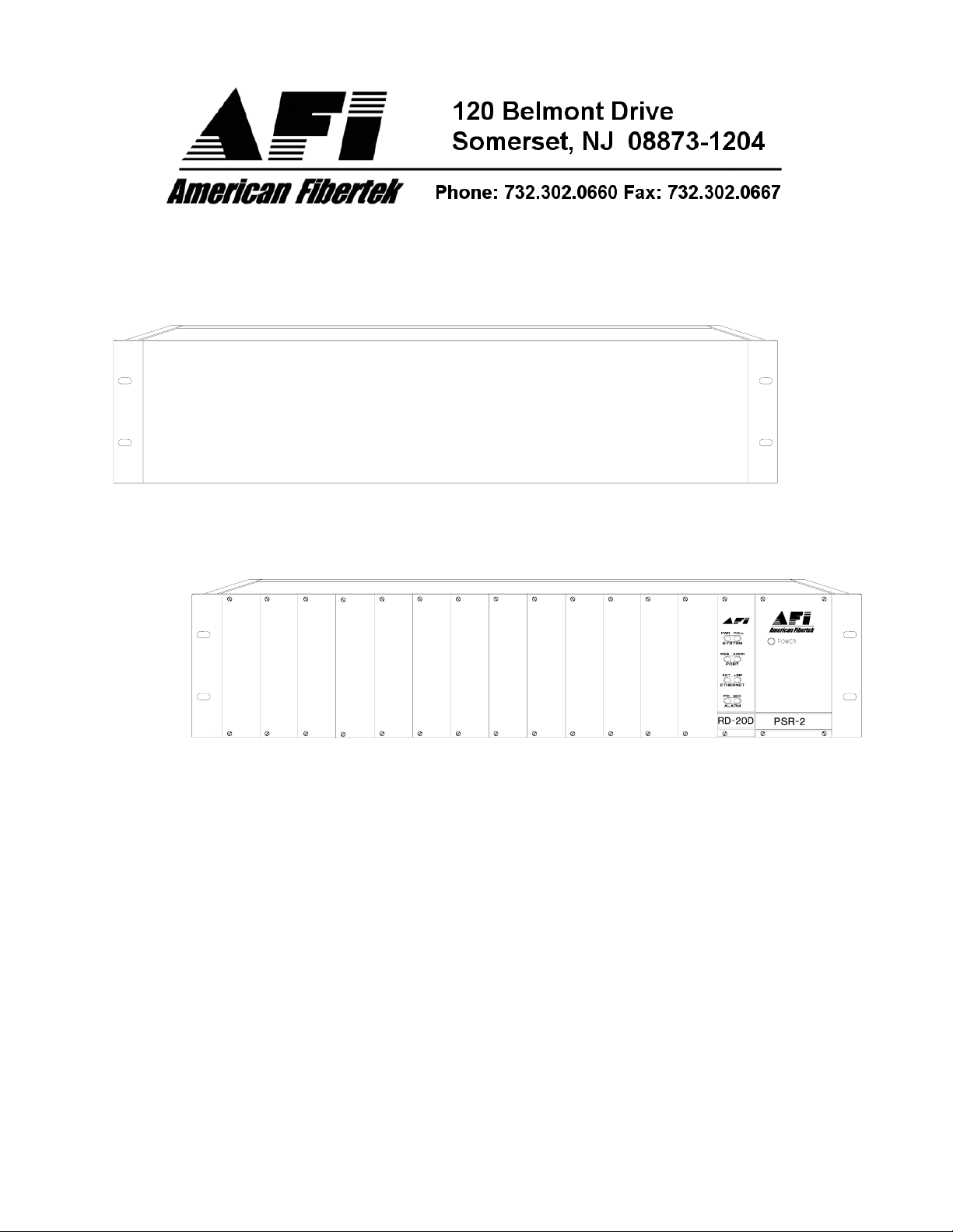
FUNCTIONAL DESCRIPTION
The SR-20D sub-rack is a standard 19" x 5.25" frame designed to accommodate up to thirteen
fiber optic plug-in cards along with a RD-20D diagnostic card and a PSR-2 power supply. The
SR-20D has a built in capability to be remotely monitored through the AFINETY Remote
Diagnostics System. A RD-20D diagnostic card is required to facilitate this feature. Please refer
to the RD-20D Instruction Manual for proper operation of this feature.
SYSTEM COMPATIBILITY
Any plug in card with the model number beginning with the letter "R" can be inserted into any of
the thirteen application slots on the left-hand side of the SR-20D.
INSTALLATION
THIS INSTALLATION OF THIS UNIT SHOULD BE MADE BY A QUALIFIED SERVICE
PERSON(S) AND MUST CONFORM TO ALL LOCAL CODES.
The SR-20D may be mounted, using standard hardware, in an upright position, with the
backplane upward, inside a standard 19” EIA rack cabinet. It is important, as with any electronic
equipment, to provide sufficient airflow to prevent over heating in the cabinet. At least 1 3/4"
(1RU) of space should be allowed above and below the SR-20D to provide air flow. If more than
one SR-20D racks are installed, forced airflow may be necessary depending upon the number
of plug-in cards used in the over-all installation. It is necessary to add a 1RU fan unit at the top
of every three SR-20D sub-racks with 1RU spacing between them.
The far right hand position of the SR-20D is only compatible with a PSR-2 series plug in power
supply. Please refer to PSR-2 instruction manual for further information. The RD-20D should be
inserted in the slot immediately to the left of the power supply. Insert the card all the way until
the edge fingers meet the internal bus connector and the front panel is even with the front of the
sub-rack. Then secure the ¼ turn fasteners by pushing with a small screwdriver, turning the
screw 90 degrees clockwise and releasing pressure. All remaining applications cards are
inserted in a similar manner. Any card may be used in any open slot.
3
Page 4

LIFETIME WARRANTY INFORMATION
American Fibertek, Inc warrants that at the time of delivery the products delivered will be free of
defects in materials and workmanship. Defective products will be repaired or replaced at the
exclusive option of American Fibertek. A Return Material Authorization (RMA) number is
required to send the products back in case of return. All returns must be shipped prepaid. This
warranty is void if the products have been tampered with. This warranty shall be construed in
accordance with New Jersey law and the courts of New Jersey shall have exclusive jurisdiction
over this contract. EXCEPT FOR THE FOREGOING WARRANTY, THERE IS NO WARRANTY
OF MERCHANTABILITY OR FITNESS FOR A PARTICULAR PURPOSE OR OTHERWISE,
EXPRESSED OR IMPLIED, WHICH EXTENDS BEYOND THE WARRANTY SET FORTH IN
THIS AGREEMENT. In any event, American Fibertek will not be responsible or liable for
contingent, consequential, or incidental damages. No agreement or understanding, expressed
or implied, except as set forth in this warranty, will be binding upon American Fibertek unless in
writing, signed by a duly authorized officer of American Fibertek.
SERVICE INFORMATION
There are no user serviceable parts inside the unit.
In the event that service is required to this unit, please direct all inquiries to:
American Fibertek, Inc. Phone: (877) 234-7200
120 Belmont Drive Phone: (732) 302-0660
Somerset, NJ 08873 FAX (732) 302-0667
E-mail: techinfo@americanfibertek.com
4
 Loading...