

Page 1
SM8P-SFP
6-Port 100/1000 SFP with
2 RJ-45/100/1000 SFP Combo Port
Managed Switch
Instruction Manual
Page 2

18-May-11
Regulatory Approval
-
FCCClassA
-UL 1950
-CSAC22.2No.950
-EN60950
-
CE
-
EN55022ClassA
-EN55024
CanadianEMINotice
ThisClassAdigitalapparatusmeetsall the requirementsoftheCanadianInterference-CausingEquipment
Regulations.
Cetappareilnumeriquedela classeArespectetoutesles exigencesdu Reglementsurlematerielbrouilleur
duCanada.
EuropeanNotice
ProductswiththeCEMarkingcomplywithboththe EMC Directive(89/336/EEC)andthe Low Voltage
Directive(73/23/EEC)issuedby the CommissionoftheEuropeanCommunityCompliancewiththese
directivesimplyconformitytothe followingEuropeanNorms:
EN55022(CISPR22)-RadioFrequencyInterference
EN61000-X-ElectromagneticImmunity
EN60950(IEC950)-ProductSafety
Page 3

18-May-11
Table of Contents
1.0 INTRODUCTION........................................................................................................................ 2
1-1.Overviewof Sm8p-Sfp..............................................................................................................................2
1-2.Checklist ...........................................................................................................................................6
1-3.Features......................................................................................................................................................6
1-4.Full View of Sm8p-Sfp .............................................................................................................................8
1-4-1.UserInterfacesontheFrontPanel(Button,LedsandPlugs)......................................................... 8
1-4-2.AcPowerInputontheRearPanel..............................................................................................9
1-5.View of the Optional Modules.........................................................................................................10
2.0 INSTALLATION................................................................................................................................11
2-1. Starting SM8P-SFP Up...................................................................................................................11
2-1-1. Hardware and Cable Installation...........................................................................................11
2-1-2. Installing Chassis to a 19-Inch Wiring Closet Rail...............................................................13
2-1-3. Cabling Requirements..........................................................................................................13
2-1-3-1. Cabling Requirements for TP Ports...............................................................................13
2-1-3-2. Cabling Requirements for 100/1000M SX/LX SFP Module.........................................13
2-1-3-3. Switch Cascading in Topology .....................................................................................14
2-1-4. Configuring the Management Agent of SM8P-SFP..............................................................17
2-1-4-1. Configuring the Management Agent of SM8P-SFP through the Console RJ-45 Port ...17
2-1-4-2. Configuring the Management Agent of SM8P-SFP through the Ethernet Port .............19
2-1-5. IP Address Assignment.........................................................................................................20
2-2. Typical Applications.......................................................................................................................24
3.0 OPERATIONOFWEB-BASEDMANAGEMENT................................................................. 26
3-1.Web Management Home Overview.......................................................................................................28
3-1-1.SystemInformation................................................................................................................31
3-1-2.AccountConfiguration...........................................................................................................33
3-1-3.TimeConfiguration................................................................................................................34
3-1-4.IPConfiguration.....................................................................................................................37
3-1-5.LoopDetection ......................................................................................................................40
3-1-6.ManagementPolicy................................................................................................................41
3-1-7.Syslog....................................................................................................................................44
3-1-8.SystemLog............................................................................................................................45
3-1-9.VirtualStack..................................................................................................................................46
3-2.Port Configuration...................................................................................................................................48
3-2-1.PortConfiguration..................................................................................................................48
3-2-2.PortStatus......................................................................................................................................50
3-2-3.SimpleCounter......................................................................................................................53
3-2-4.DetailCounter........................................................................................................................55
3-2-5.PowerSaving.........................................................................................................................58
3-3.VLAN.............................................................................................................................................59
3-3-1.VLANMode..........................................................................................................................59
3-3-2.Tag-basedGroup...........................................................................................................................60
3-3-3.Port-basedGroup ..........................................................................................................................63
3-3-4.Ports......................................................................................................................................65
3-3-5.PortIsolation..........................................................................................................................67
3-3-6.ManagementVLAN...............................................................................................................68
3-4.MAC...............................................................................................................................................69
Page 4

Rev.A1
18-May-11
iv
3-4-1.MacAddressTable..........................................................................................................................................69
3-4-2.StaticFilter.....................................................................................................................................71
3-4-3.StaticForward.........................................................................................................................................72
3-4-4.MACAlias.....................................................................................................................................73
3-4-5.MACTable.......................................................................................................................................................74
3-5.GVRP...................................................................................................................................................... 75
3-5-1.Config............................................................................................................................................75
3-5-2.Counter..........................................................................................................................................78
3-5-3.Group......................................................................................................................................................80
3-6.QOS(QUALITYOF SERVICE)CONFIGURATION ....................................................................................81
3-6-1.Ports...............................................................................................................................................81
3-6-2.QosControlList..............................................................................................................................83
3-6-3.RateLimiters ..................................................................................................................................88
3-6-4.StormControl..........................................................................................................................................89
3-6-5.Wizard.....................................................................................................................................................90
3-7.SNMPCONFIGURATION............................................................................................................................100
3-8.ACL....................................................................................................................................................... 108
3-8-1.Ports.............................................................................................................................................108
3-8-2.RateLimiters................................................................................................................................. 110
3-8-3.AccessControlList.........................................................................................................................111
3-8-4.Wizard...................................................................................................................................................140
3-9.IPMACBINDING.................................................................................................................................146
3-10.802.1XCONFIGURATION.........................................................................................................................148
3-10-1.Server......................................................................................................................................... 152
3-10-2.PortConfiguration....................................................................................................................... 154
3-10-3.Status...................................................................................................................................................157
3-10-4.Statistics..............................................................................................................................................158
3-11.TACACS+.....................................................................................................................................................159
3-11-1.State.....................................................................................................................................................159
3-11-2.Authentication............................................................................................................................ 160
3-11-3.AUTHORIZATION...........................................................................................................................161
3-11-4.ACCOUNTING .........................................................................................................................162
3-12.TrunkingConfiguration................................................................................................................................163
3-12-1.Port............................................................................................................................................. 164
3-12-2
AggregatorView....................................................................................................................................................166
3-12-3
AggregationHashMode............................................................................................................... 167
3-12-4
3-13
3-14
3-15.MIRROR .............................................................................................................................................186
3-16.MULTICAST................................................................................................................................................188
LACPSystemPriority............................................................................................................... 168
STPCONFIGURATION..............................................................................................................................169
3-13-1.Status..................................................................................................................................................169
3-13-2.Configuration.............................................................................................................................171
3-13-3.STPPortConfiguration............................................................................................................... 173
MSTP.................................................................................................................................................. 176
3-14-1
Status...................................................................................................................................................176
3-14-2
RegionConfig.............................................................................................................................177
3-14-3
InstanceView...............................................................................................................................................178
3-16-1
IGMPmode................................................................................................................................. 188
3-16-2
IGMPProxy.........................................................................................................................................189
3-16-3
IGMPSnooping...........................................................................................................................191
3-16-4
IGMPGroupAllow .....................................................................................................................192
3-16-5
IGMPGroupMembership............................................................................................................193
3-16-6MVR...........................................................................................................................................194
3-16-7MVID.........................................................................................................................................195
Page 5

iii
Rev.A1
18-May-11
3-16-8
MVRGroupAllow ..................................................................................................................... 196
3-16-9
3-17.ALARMCONFIGURATION.....................................................................................................................198
3-18.DHCPSNOOPING............................................................................................................................. 201
3-19.LLDP.................................................................................................................................................. 204
3-20.SAVE/RESTORE........................................................................................................................................210
3-21.EXPORT/IMPORT.....................................................................................................................................213
3-22.DIAGNOSTICS ................................................................................................................................. 214
3-23.MAINTENANCE............................................................................................................................... 216
3-24.LOGOUT ........................................................................................................................................... 217
MVRGroupMembership............................................................................................................ 197
3-17-1
Events........................................................................................................................................ 198
3-17-2
Email ......................................................................................................................................... 200
3-18-1.DHCPSnoopingState.........................................................................................................................201
3-18-2.DHCPSnoopingEntry................................................................................................................ 202
3-18-3.DHCPSnoopingClient ............................................................................................................... 203
3-19-1
.LLDPState........................................................................................................................................204
3-19-2
.LLDPEntry .............................................................................................................................. 206
3-19-3
.LLDPCounter .......................................................................................................................... 208
3-20-1.FactoryDefaults...........................................................................................................................211
3-20-2
.SaveStart...........................................................................................................................................211
3-20-3
.SaveUser...................................................................................................................................211
3-20-4
.RestoreUser.............................................................................................................................. 212
3-22-1.Diag........................................................................................................................................... 214
3-22-2.Ping............................................................................................................................................ 215
3-23-1
.WarmRestart............................................................................................................................. 216
3-23-2
.Firmwareupgrade ..................................................................................................................... 216
4.0 OPERATIONOFCLIMANAGEMENT........................................................................................218
4-1.CLIMANAGEMENT.......................................................................................................................218
4-1-1.Login...................................................................................................................................218
4-2.COMMANDSOF CLI.......................................................................................................................220
4-2-1.GlobalCommandsofCLI.....................................................................................................221
4-2-2.LocalCommandsofCLI......................................................................................................227
5.0 MAINTENANCE............................................................................................................................318
5-1.RESOLVINGNOLINKCONDITION....................................................................................................318
5-2.Q&A ...........................................................................................................................................318
APPENDIXATECHNICALSPECIFICATIONS....................................................................................319
APPENDIX BNULL MODEM CABLE SPECIFICATI ONS ................................ ................................ ....................... 322
Page 6

18-May-11
Date Revision
18/05/2011
A1
Revision History
Page 7

v
Rev.A1
18-May-11
Warning:
Self-demolition on Product is strictly prohibited. Damage caused by self-
demolitionwill be charged forrepairingfees.
Do not placeproductat outdoor orsandstorm.
Before installation, please make sure input power supply and product
specifications are compatibleto each other.
The SSL only provide the CLI for switch management and SSH
default enable without UI for management. (The feature supports
upperFWv5.01and optional)
Before importing / exporting configurationplease make sure the
firmwareversionis alwaysthesame.
After firmware upgrade, the switch will remove the configuration
automaticallytolatestfirmwareversion.
Rev.A1 vi
Page 8

About this user’s manual
In this user’s manual, it will not only tell you how to install and connect your
network system but configure and monitor the SM8P-SFP through the built-in CLI
and web by RJ-45 Console interface and Ethernet ports step-by-step. Many
explanation in detail of hardware and software functions are shown as well as the
examples of the operation for web-based interface and command-line interface
(CLI).
Overview of this user’s manual
Chapter1 “Introduction”describesthe features of SM8P-SFP
Chapter2 “Installation”
Chapter3 “Operation of Web-based Management”
Chapter 4 “Operation of CLI Management”
Chapter5“Maintenance”
1 Rev.A0
1-Mar-11
Page 9

Page 10

Rev.A1
18-May-11
2
1. Introduction
1-1. Overview of SM8P-SFP
SM8P-SFP, 6-Port 100/1000 Dual Speed SFP + 2-Port RJ-45/100/1000
SFP Managed Switch, is a standard switch that meets all IEEE 802.3/u/x/z Gigabit
Ethernet specifications. The switch can be managed through RJ-45 console port via
directly connection, or through Ethernet port using CLI or Web-based management
unit, associated with SNMP agent. With the SNMP agent, the network administrator
can logon the switch to monitor, configure and control each port’s activity in a
friendly way. The overall network management is enhanced and the network
efficiency is also improved to accommodate high bandwidth applications. In addition,
the switch features comprehensive and useful function such as ACL, IP-MAC
Binding, DHCP Option 82, QoS (Quality of Service), Spanning Tree, VLAN, Port
Trunking, Bandwidth Control, Port Security, SNMP/RMON, IGMP Snooping
capability via the intelligent software. It is suitable for both metro-LAN and office
application.
Others the switch increase support the Power saving for reduce the power
consumption with "ActiPHY Power Management" and "PerfectReach Power
Management" two technique.It could efficient saving the switch power with auto
detectthe client idle and cable length to provide different power.
In this switch, Port 7 and Port 8 include two types of media --- TP and
(100/1000M) SFP Fiber (LC, BiDi LC…); this port supports 10/100/1000Mbps TP or
100/1000 Dual Speed SFP Fiber with auto-detected function. (100/1000M) SFP
Fibertransceiveris used forhigh-speedconnectionexpansion
1000MbpsLC, Multi-Mode,SFP Fiber transceiver
1000MbpsLC, 10km, SFP Fiber transceiver
1000MbpsLC, 30km, SFP Fiber transceiver
1000MbpsLC, 50km, SFP Fiber transceiver
1000MbpsBiDi LC, 20km, 1550nmSFPFiberWDM transceiver
1000MbpsBiDi LC, 20km,1310nmSFPFiber WDM transceiver
100Base-FXFE SFP Fiber Module, LCMulti-Mode
100Base-FXFE SFP Fiber Module, LCSingle-Mode20km
10/100/1000Mbps TP is a standard Ethernet port that meets all IEEE
802.3/u/x/z Gigabit, Fast Ethernet specifications. (100/1000M) SFP Fiber
transceiver is a Gigabit Ethernet port that fully complies with all IEEE 802.3z and
1000Base-SX/LXstandards and100-FXstandards.
1000Mbps Single Fiber WDM (BiDi) transceiver is designed with an optic
Wavelength Division Multiplexing (WDM) technology that transports bi-directional
full duplex signal overa single fiber simultaneously.
For upgrading firmware, please refer to the Section 3-21 or Section 4-2-2 for
more details. The switch will not stop operating while upgrading firmware and after
that,the configurationkeeps unchanged.
The switch also supports the IEEE Standard─ ─ 802.1AB ( Link Layer
Discovery Protocol),Provide more easy debug tool and enhance the networking
management availability, Others it can provide auto-discovery device and topology
Page 11

3
Rev.A1
18-May-11
providing.
Page 12

Rev.A1
18-May-11
4
•
KeyFeaturesinthe Device
QoS:
Support Quality of Service by the IEEE 802.1P standard. There are two
priorityqueueand packettransmissionschedule.
SpanningTree:
Support IEEE 802.1D, IEEE 802.1w (RSTP: Rapid Spanning Tree
Protocol) standards.
VLAN:
Support Port-based VLAN and IEEE802.1Q TagVLAN. Support 256 active
VLANs and VLAN ID 1~4094.
PortTrunking:
Supportstatic port trunking and port trunking with IEEE 802.3ad LACP.
BandwidthControl:
Supportingress and egress perport bandwidthcontrol.
PortSecurity:
Supportallowed,deniedforwardingand port securitywith MAC address.
Link Layer DiscoveryProtocol(LLDP):
IEEE Standard─ ─ 802.1AB (Link Layer Discovery Protocol),Provide
more easy debug tool and enhance the networking management availability,
Othersit can provideauto-discovery device and topology providing
SNMP/RMON:
SNMP agent and RMON MIB. In the device, SNMP agent is a client
software which is operating over SNMP protocol used to receive the
command from SNMP manager (server site) and echo the corresponded
data, i.e. MIB object. Besides, SNMP agent will actively issue TRAP
informationwhen happened.
RMON is the abbreviation of Remote Network Monitoring and is a branch of
the SNMP MIB.
The device supports MIB-2 (RFC 1213), Bridge MIB (RFC 1493), RMON
MIB (RFC 1757)-statistics Group 1,2,3,9, Ethernet-like MIB (RFC 1643),
EthernetMIB (RFC 1643) and so on.
IGMPSnooping:
Support IGMP version 2 (RFC 2236): The function IGMP snooping is used
to establish the multicast groups to forward the multicast packet to the
member ports, and, in nature, avoid wasting the bandwidth while IP
multicastpacketsare running over thenetwork.
IGMPProxy:
The implementation of IP multicast processing. The switch supports IGMP
version 1 and IGMP version 2, efficient use of network bandwidth, and fast
response time for channel changing. IGMP version 1 (IGMPv1) is
described in RFC1112 ,and IGMP version 2 (IGMPv2) is described in RFC
2236. Hosts interact with the system through the exchange of IGMP
messages. Similarly, when you configure IGMP proxy, the system interacts
Page 13

5
Rev.A1
18-May-11
with the router on its upstream interface through the exchange of IGMP
messages. However, when acting as the proxy, the system performs the
host portion of the IGMP task onthe upstream interfaceas follows:
When queried, sends group membershipreports to the
group.
When one of its hostsjoins a multicast address group to
which none of its other hosts belong,sends unsolicited
group membershipreportsto that group.
When the lastof its hosts in a particular multicast group
leaves the group,sends an unsolicited leave group
membershipreportto the all-routers group (244.0.0.2).
PowerSaving:
The Power saving using the "ActiPHY Power Management" and
"PerfectReach Power Management" two techniques to detect the client idle
and cable length automatically and provides the different power. It could
efficientto save theswitch power andreduce the powerconsumption.
Q-
in-QVLAN for performance & security:
The VLAN feature in the switch offers the benefits of both security and
performance. VLAN is used to isolate traffic between different users and
thus provides better security. Limiting the broadcast traffic to within the
same VLAN broadcast domain also enhances performance. Q-in-Q, the use
of double VLAN tags is an efficient method for enabling Subscriber
Aggregation.Thisis very usefulin the MAN.
MVR:
Multicast VLAN Registration (MVR) can support carrier to serve content
provider using multicast for Video streaming application in the network.
Each content provider Video streaming has a dedicated multicast VLAN.
The MVR routes packets received in a multicast source VLAN to one or
more receive VLANs. Clients are in the receive VLANs and the multicast
serveris inthe source VLAN.
AccessControl List (ACL):
The ACLs are divided into EtherTypes. IPv4, ARP protocol, MAC and VLAN
parameters etc. Here we will just go over the standard and extended
access lists for TCP/IP. As you create ACEs for ingress classification, you
can assign a policy for each port, the policy number is 1-8, however, each
policy can be applied to any port. This makes it very easy to determine what
type of ACL policy youwillbe workingwith.
IP-MAC-PortBinding:
The IP network layer uses a four-byte address. The Ethernet link layer uses
a six-byte MAC address. Binding these two address types together allows
the transmission of data between the layers. The primary purpose of IPMAC binding is to restrict the access to a switch to a number of authorized
users. Only the authorized client can access the Switch’s port by checking
the pair of IP-MAC Addresses and port number with the pre-configured
database. If an unauthorized user tries to access an IP-MAC binding
enabledport, the systemwill block the access by droppingitspacket.
Page 14

Rev.A1
18-May-11
6
SSLand SSHfor secure Management: (Optional by Project Requirement, Refer
to device’sFW v5.0x upper)
Secure Sockets Layer (SSL) supports the encryption for all HTTP traffic,
allowing secure access to the browser-based management GUI in the
switch. And Secure Shell (SSH) which supports the encryption for all
transmitted data for secure, remote command-line interface (CLI) access
overIP networks
Note: The SSL only provide the CLI for switch management and SSH
defaultenablewithoutUI for management.
TACACS+: (Optional by Project Requirement, Refer to device’s FW v5.0x
upper)
The switch supports to ease switch management security administration by
using a password with CiscoTACACS+authenticationserver
Syslog:
The Syslog is a standard for logging program messages . It allows
separation of the software that generates messages from the system that
stores them and the software that reports and analyzes them. It is
supported by a wide variety of devices and receivers across multiple
platforms.
Page 15

7
Rev.A1
18-May-11
1-2. Checklist
Before you start installingthe switch,verify that the packagecontains the
following:
SM8P-SFP 6-Port 100/1000 Dual SpeedSFP + 2-PortRJ-45/100/1000 SFP
ManagedSwitch
ThisUser's Manual in CD-ROM
AC Power Cord
RJ-45transformRS-232Cable
Please notify your sales representative immediatelyif anyof the aforementioned
items is missingor damaged.
1-3. Features
The SM8P-SFP, a standalone off-the-shelf switch, provides the
comprehensive features listed below for users to perform system network
administrationand efficientlyand securely serveyour network.
•
Hardware
•
6 100/1000M Fiber SFP ports
•
2 10/100/1000MbpsTP or 100/1000Dual SpeedSFPFiber dual mediaauto
sense
•
1392KBon-chipframe buffer
•
Supportjumbo frame up to 9600bytes
•
Programmableclassifier for QoS(Layer 4/Multimedia)
•
8K MAC address and4K VLAN support(IEEE802.1Q)
•
Per-portshaping,policing,and BroadcastStormControl
•
PowerSavingwith "ActiPHYPowerManagement"and"PerfectReachPower
Management"techniques.
•
IEEE802.1QQ-in-QnestedVLANsupport
•
Full-duplexflow control(IEEE802.3x) and half-duplex backpressure
•
Extensivefront-panel diagnostic LEDs; System: Power, SFP Port1-8: LINK/ACT,
100/1000M,TP Port7-8:TP(LINK/ACT/Speed)
•
Management
•
Supportsconciselythe status of port and easilyport configuration
•
Supportsper port traffic monitoring counters
•
Supports a snapshotof the systemInformationwhen you login
•
Supports port mirror function
•
Supports the static trunk function
•
Supports 802.1Q VLAN
•
Supports user management and limitsthree users to login
Page 16

Rev.A1
18-May-11
8
•
Maximalpacket length can be up to 9600 bytesfor jumbo frameapplication
•
Supports DHCP BroadcastingSuppressionto avoid network suspendedor
crashed
•
Supports to sendthe trap eventwhilemonitoredeventshappened
•
Supports Link Layer Discovery Protocol (LLDP)
•
Supports default configuration which can be restored to overwrite the current
configurationwhichis workingon via webbrowser and CLI
•
Supports on-line plug/unplugSFP modules
•
Supports Quality of Service(QoS) for realtime applicationsbased on the
informationtaken from Layer 2 to Layer 4, suchas VoIP
•
Built-inweb-basedmanagementandCLI management, providinga more
convenientUI for the user
•
Supports port mirror functionwithingress/egresstraffic
•
Supportsrapidspanningtree(802.1wRSTP)
•
Supportsmultiplespanningtree(802.1sMSTP)
•
Supports SSL/SSH supports the encryptionfor all transmitted data for secure
•
Supports ease switch managementsecurity administration by using a password
withCiscoTACACS+authenticationserver
•
Supports 802.1X port securityon a VLAN
•
Supports IP-MAC-Port Bindingfor LAN security
•
Supports user management and only first login administratorcan configure the
device.The rest of users canonly view the switch
•
SNMPaccesscan be disabledand prevent from illegalSNMP access
•
Supports Ingress, Non-unicast and Egress Bandwidth rating management with
a resolution of 1Mbps
•
The trap eventand alarm message can be transferred via e-mail
•
Supports diagnostics to let administrator knowing the hardwarestatus
•
Supports loop detection to protect the switch crash when the networking has
loopingissue
•
HTTP and TFTP for firmware upgrade, system log upload and configuration file
import/export
•
Supports remote bootthe device through user interface andSNMP
•
Supports NTP network time synchronization and daylight saving
•
Supports 120 event log records in the mainmemory and display on the local
console
•
Supports Syslog a standard for logging program messages and allows
separationof the softwarethat generates messages from thesystem
Page 17
9
Rev.A1
18-May-11
1-4. Full View of SM8P-SFP
Fig. 1-1 Full View of SM8P-SFP
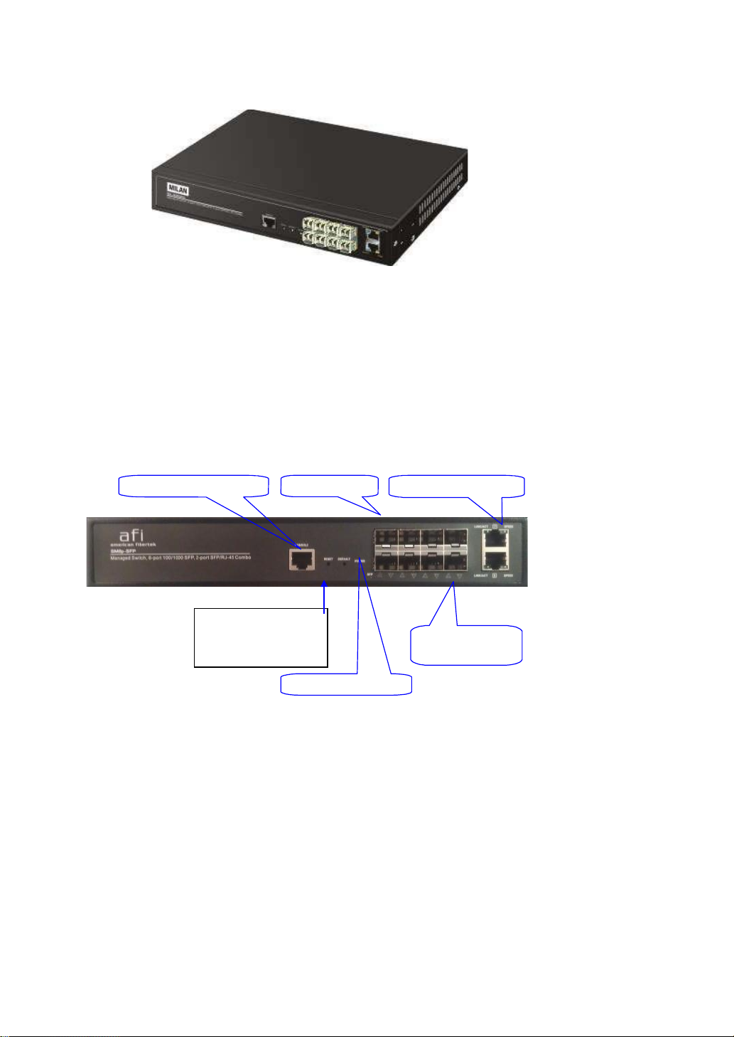
1-4-1.User Interfaceson the FrontPanel (Button,LEDsand Plugs)
There are 6 TP Gigabit Ethernet ports and 2 SFP fiber ports for optional
removable modules for optional removable modules on the front panel of the switch.
LED display area, locating on the left side of the panel, contains a Power LED,
which indicates the power status and 8 ports working status of the switch. One RJ45 Console interface is offeredfor configuration or management.
RJ-45 Console Interface SFP Fiber Port Gigabit Ethernet Port
RESET Button:
RESET button is used
to reset the
management system.
Power Indication LED
Fig. 1-2 Front View of SM8P-SFP
Fiber Port Status
Indication LEDs
Page 18

Rev.A1
18-May-11
10
•
LED
Color
Function
SystemLED
POWER
Green
Lit when poweris on and good
100/1000 SFP Port 1 to 8 LED
LINK/ACT
Green/
Amber
Lit Green whenSFP link on 1000Mbpsspeed
LitAmberwhen SFP linkon 100Mbps speed
Blinks when anytrafficis present
TP Port 7, 8 LED
LINK/ACT
Green
Lit Green whenTP link good
Blinks when anytrafficis present
Speed
Green/
Amber
Lit Green whenTP link on 1000Mbps speed
Lit Amber whenTP link on 100Mbps speed
Off when 10Mbpsor no link occur
LEDIndicators
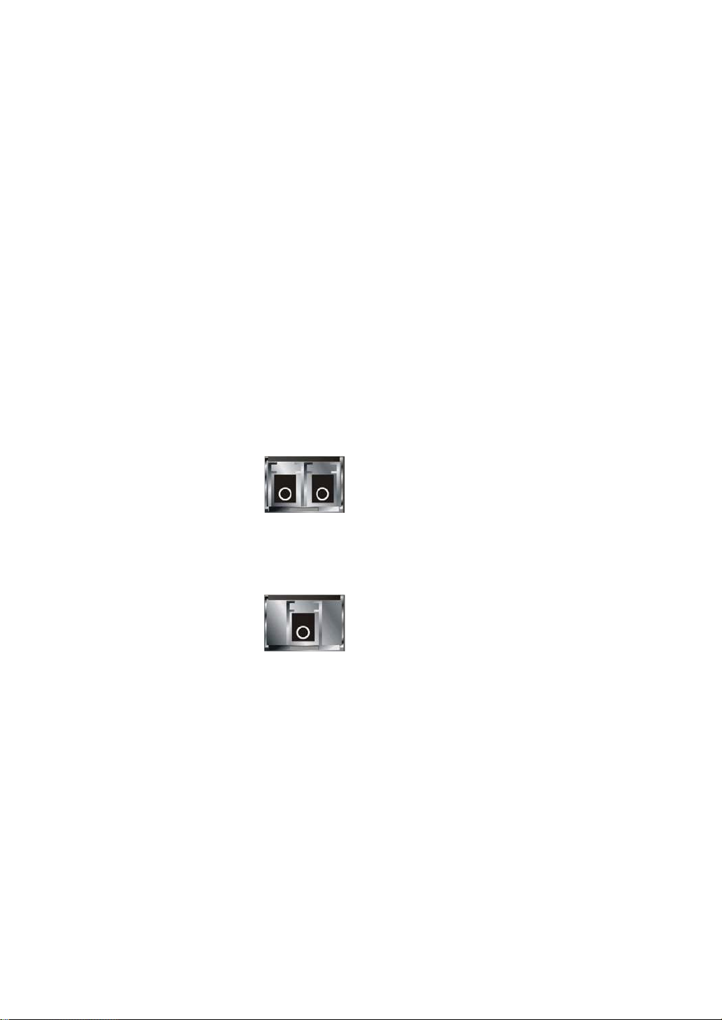
1-4-2.AC PowerInputon the Rear Panel
One socket onthe rear panel is forAC power input.
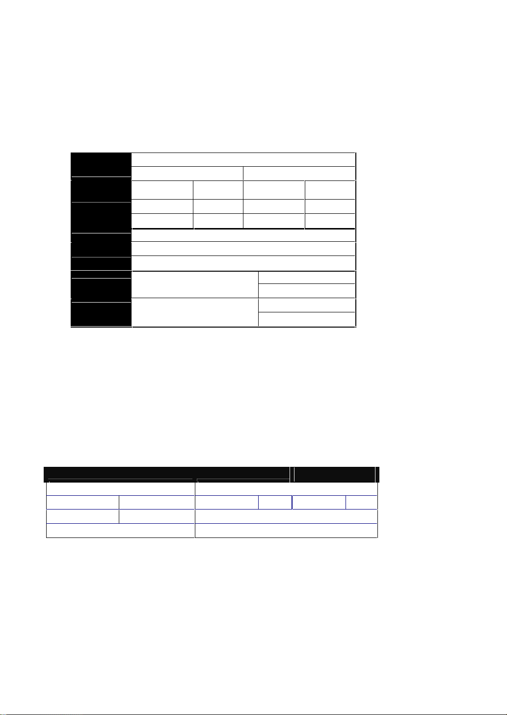
Table1-1
AC Line 100-240V 50/60 Hz
Fig. 1-3 Rear View of SM8P-SFP
Page 19
11
Rev.A1
18-May-11
1-5. View of the Optional Modules
In the switch, Port 7~8 includes two types of media --- TP and SFP Fiber (LC,
BiDi LC…); this port supports 10/100/1000Mbps TP or 100/1000 Dual Speed SFP
Fiber with auto-detected function. 100/1000 Dual Speed SFP Fiber transceiver is
used for high-speed connection expansion; the following are optional SFP types
providedfor the switch:
1000Mbps LC, MM, SFP Fibertransceiver(SFP.LC)
1000Mbps LC, SM 10km, SFP Fiber transceiver (SFP.LC.S10)
1000Mbps LC, SM 30km, SFP Fiber transceiver (SFP.LC.S30)
1000Mbps LC, SM 50km, SFP Fiber transceiver (SFP.LC.S50)
1000Mbps BiDiLC, type 2, SM 20km,SFP Fiber WDM transceiver ,
1310nm (SFP.BL3.S20)
1000Mbps BiDiLC, type 1, SM 20km,SFPFiberWDM transceiver
1550nm (SFP.BL5.S20)
100Base-FX FE SFPFiber Module, LC Multi-Mode(SFP.FLC)
100Base-FX FE SFPFiberModule,LC Single-Mode 20km (SFP.FLC.S20)
Fig. 1-4 100/ 1000M-FX/SX/LX LC, SFP Fiber Transceiver
Fig. 1-5 Front View of 1000Base-LXBiDi LC, SFP Fiber Transceiver
Page 20
Rev.A1
18-May-11
12
2. Installation
2-1. Starting SM8P-SFP Up
Thissection will give users a quick start for:
- Hardwareand Cable Installation
-
ManagementStationInstallation
-
Softwarebootingandconfiguration
2-1-1.HardwareandCableInstallation
At the beginning,pleasedo first:
Weara grounding device to avoid the damagefrom electrostaticdischarge
Besurethat powerswitchis OFFbefore youinsertthe powercord to power
source
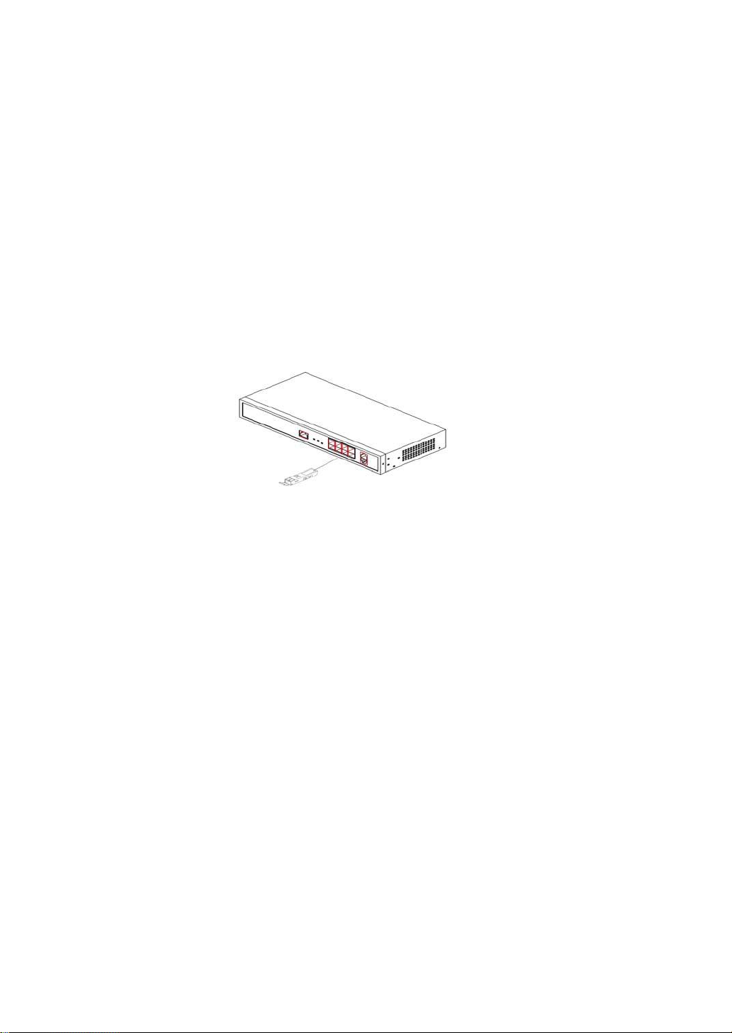
•
Installing Optional SFP Fiber Transceiversto the SM8P-SFP
Note: If youhave no modules,please skip this section.
Fig. 2-1 Installation of Optional SFP Fiber Transceiver
•
Connectingthe SFP Module to the Chassis:
The optional SFP modulesare hot swappable, so you can plug or unplugit
beforeor after poweringon.
1.
Verifythat the SFP module is the right modeland conforms to the chassis
2.
Slide the modulealong the slot. Alsobe sure that the moduleis properly
seatedagainstthe slot socket/connector
3.
Installthe media cablefor network connection
4.
Repeat the abovesteps, as needed,for each moduleto be installed into
slot(s)
5.
Havethe power ON after the aboveproceduresare done
Page 21

13
Rev.A1
18-May-11
• TP Port and CableInstallation
In the switch, TP port supports MDI/MDI-X auto-crossover, so both types of
cable, straight-through (Cable pin-outs for RJ-45 jack 1, 2, 3, 6 to 1, 2, 3, 6 in
10/100M TP; 1, 2, 3, 4, 5, 6, 7, 8 to 1, 2, 3, 4, 5, 6, 7, 8 in Gigabit TP) and
crossed-over (Cable pin-outs for RJ-45 jack 1, 2, 3, 6 to 3, 6, 1, 2) can be used.
It means youdo not have to tell from them,just plug it.
Use Cat. 5 grade RJ-45 TP cable to connect to a TP port of the switch and the
other end is connected to a network-aware device such as a workstation or a
server.
Repeat the above steps, as needed, for each RJ-45 port to be connected to a
Gigabit10/100/1000TP device.
Now, you canstart having theswitch in operation.
•
Power On
The switch supports 100-240 VAC, 50-60 Hz power supply. The power
supply will automatically convert the local AC power source to DC power. It does not
matter whether any connection plugged into the switch or not when power on, even
modules as well. After the power is on, all LED indicators will light up immediately
and then all off except the power LED still keeps on. This represents a reset of the
system.
•
FirmwareLoading
After resetting, the bootloader will load the firmware into the memory. It will
take about 30 seconds, after that, the switch will flash all the LED once and
automaticallyperforms self-test and is in readystate.
Page 22

Rev.A1
18-May-11
14
2-1-2.InstallingChassisto a 19-Inch WiringClosetRail
Fig. 2-2
Caution:Allow a proper spacingand proper air ventilationfor the coolingfan
at both sidesof the chassis.
Weara groundingdevicefor electrostatic discharge.
Screw the mountingaccessoryto the front side of the switch(See Fig. 2-2).
Place the Chassisinto the 19-inch wiring closet rail and locate it at the proper
position.Then,fix the Chassisby screwing it.
2-1-3.CablingRequirements
To help ensure a successful installation and keep the network performance
good, please take a care on the cabling requirement. Cables with worse
specificationwillrender the LANto work poorly.
2-1-3-1.Cabling Requirementsfor TP Ports
For Fast EthernetTP network connection
The grade ofthe cable must be Cat. 5 or Cat. 5e with a maximum lengthof
100meters.
Gigabit Ethernet TP networkconnection
The grade ofthe cable must be Cat. 5 or Cat. 5e with a maximum lengthof
100 meters. Cat. 5eis recommended.
2-1-3-2.Cabling Requirementsfor 100/1000MSX/LX SFP Module
It is more complex and comprehensive contrast to TP cabling in the fiber
media. Basically, there are two categories of fiber, multi mode (MM) and single
mode (SM). The later is categorized into several classes by the distance it supports.
They are SX, LX, LHX, XD, and ZX. From the viewpoint of connector type, there
mainlyare LC and BIDI LC.
Page 23
15
Rev.A1
18-May-11
Gigabit Fiber withmulti-modeLC SFP module
Multi-mode Fiber Cable and Modal Bandwidth
Multi-mode 62.5/125m
Multi-mode 50/125m
Modal
Bandwidth
Distance
Modal
Bandwidth
Distance
160MHz-Km
220m
400MHz-Km
500m
IEEE 802.3z
Gigabit Ethernet
1000SX 850nm
200MHz-Km
275m
500MHz-Km
550m
Single-mode Fiber 9/125m
Single-mode transceiver 1310nm 10, 30Km
1000BaseLX/LHX/XD/ZX
Single-mode transceiver 1550nm 50Km
TX(Transmit) 1310nm
Single-Mode
*20Km
RX(Receive) 1550nm
TX(Transmit) 1550nm
1000Base-LX
Single Fiber
(BIDI LC)
Single-Mode
*20Km
RX(Receive) 1310nm
1000Base-XTP,Fiber
100Base-TXTP
100Base-FXFiber
Round trip Delay: 4096
Round trip Delay: 512
Cat. 5 TP Wire:
11.12/m
Cat. 5 TP Wire:
1.12/m
Fiber Cable:
1.0/m
Fiber Cable :
10.10/m
TP to fiber Converter: 56
Bit Timeunit : 1ns (1sec./1000 Mega bit)
Bit Time unit: 0.01s (1sec./100Mega bit)
Gigabit Fiber withsingle-modeLCSFP module
100Base-FX FE SFPFiberModule,LC Multi-Mode
100Base-FX FE SFPFiberModule,LC Single-Mode
Gigabit Fiberwith BiDi LC 1310nmSFP module
Gigabit Fiberwith BiDi LC 1550nmSFP module
The following table liststhe types of fiber that we supportand those elsenot
listed here are availableuponrequest.
Table2-1
2-1-3-3.SwitchCascadinginTopology
•
Takesthe Delay Time intoAccount
Theoretically, the switch partitions the collision domain for each port in switch
cascading that you may up-link the switches unlimitedly. In practice, the network
extension (cascading levels & overall diameter) must follow the constraint of the
IEEE 802.3/802.3u/802.3z and other 802.1 series protocol specifications, in which
the limitations are the timing requirement from physical signals defined by 802.3
series specification of Media Access Control (MAC) and PHY, and timer from some
OSI layer 2 protocols such as802.1d, 802.1q, LACP andso on.
The fiber,TP cables anddevices’bit-time delay(roundtrip) are as follows:
Table 2-2
Page 24
Rev.A1
18-May-11
16
Sum up all elements’ bit-time delay and the overall bit-time delay of
wires/devices must be within Round Trip Delay (bit times) in a half-duplex network
segment (collision domain). For full-duplex operation, this will not be applied. You
may use the TP-Fiber module to extend the TP node distance over fiber optic and
providethe long haul connection.
•
TypicalNetworkTopologyin Deployment
A hierarchical network with minimum levels of switch may reduce the timing
delay between server and client station. Basically, with this approach, it will
minimize the number of switches in any one path; will lower the possibility of
network loop and will improve network efficiency. If more than two switches are
connected in the same network, select one switch as Level 1 switch and connect all
other switches to it at Level 2. Server/Host is recommended to connect to the Level
1 switch. This is general if no VLANor other specialrequirementsare applied.
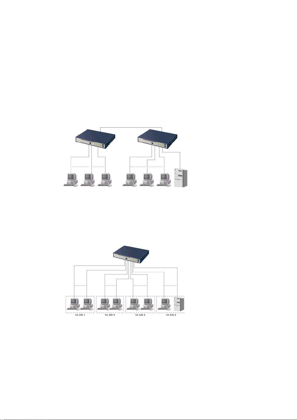
Case1:All switch ports arein the samelocal area network. Every port can access
each other (See Fig. 2-3).
Fig. 2-3 No VLAN Configuration Diagram
If VLAN is enabled and configured, each node in the network that can
communicateeachother directly is boundedin the same VLAN area.
Here VLAN area is defined by what VLAN you are using. The switch
supports both port-based VLAN and tag-based VLAN. They are different in practical
deployment, especially in physical location. The following diagram shows how it
works and whatthe differencethey are.
Case2a:Port-basedVLAN(SeeFig.2-4).
Fig. 2-4 Port-based VLAN Diagram
Page 25
17
Rev.A1
18-May-11
1.
The same VLANmembers could not be in differentswitches.
2.
Every VLAN members couldnot access VLANmemberseach other.
3.
The switch managerhas to assigndifferentnamesfor eachVLAN groups
at one switch.
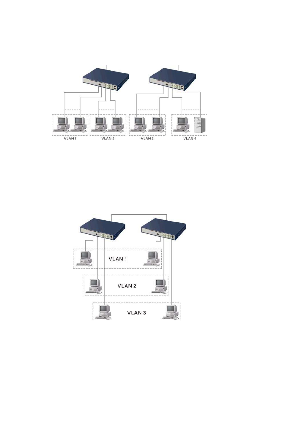
Case 2b: Port-based VLAN (See Fig.2-5).
Fig. 2-5 Port-based VLAN Diagram
1.
VLAN1 members could not accessVLAN2,VLAN3 and VLAN4 members.
2.
VLAN2 members could not accessVLAN1 and VLAN3members,butthey could
accessVLAN4members.
3. VLAN3 members could not accessVLAN1,VLAN2 and VLAN4.
4.
VLAN4 members could not accessVLAN1 and VLAN3members,butthey could
accessVLAN2members.
Case3a: The same VLAN members can beat different switches with the same VID
(See Fig. 2-6).
Fig. 2-6 Attribute-based VLAN Diagram
Page 26
Rev.A1
18-May-11
18
2-1-4.ConfiguringtheManagementAgentofSM8P-SFP
We offer you three ways to startup the switch management function. They
are RJ-45 console, CLI, and Web. Users can use any one of them to monitor and
configurethe switch. Youcan touch them through the followingprocedures.
Section2-1-4-1:Configuringthe ManagementAgent of SM8P-SFPthrough the
ConsoleRJ-45Port
Section2-1-4-2:Configuringthe ManagementAgent of SM8P-SFPthrough the
EthernetPort
Note: Please first modifythe IP address, Subnet mask,Defaultgatewayand DNS
throughRJ-45console, and thendo the next.
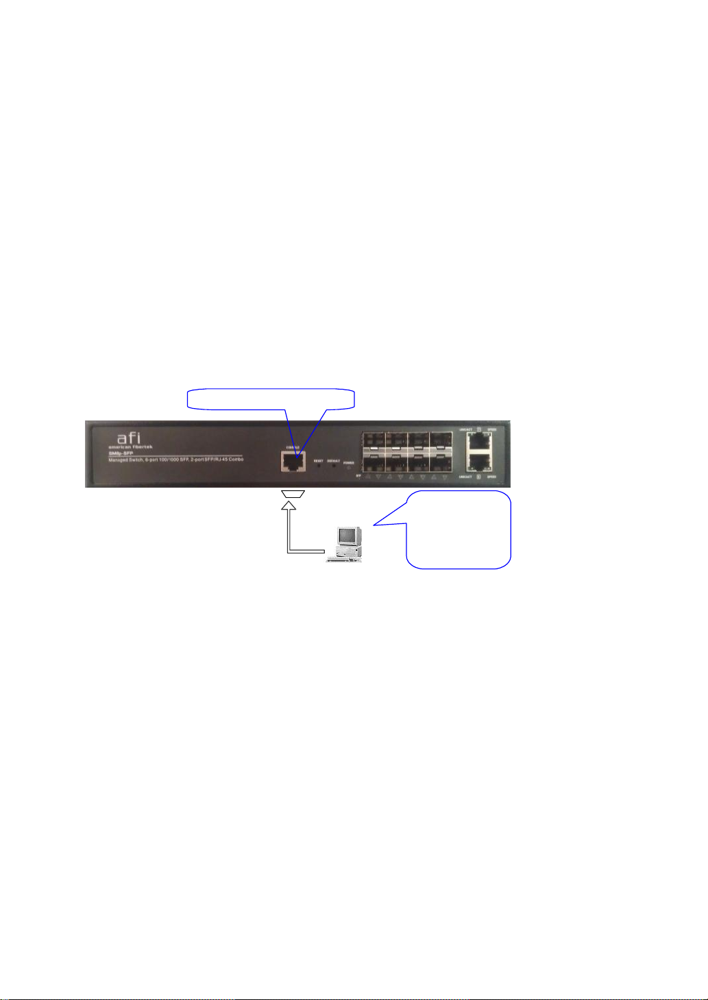
2-1-4-1.Configuringthe ManagementAgent of SM8P-SFPthrough the Console
RJ-45 Port
To perform the configuration through RJ-45 console port, the switch’s
console port must be directly connected to a DCE device, for example, a PC,
through RJ-45 transform RS-232 cable with RJ-45 connector. Next, run a terminal
emulator with the default setting of the switch’s serial port. With this, you can
communicatewiththeswitch.
In the switch, RJ-45 interface only supports baud rate 115200 bps with 8 data
bits, 1 stop bit, no paritycheck and no flow control.
RJ-45 Console Connector
SM8P-SFP L2 Managed Switch
Default IP Setting:
IP address = 192.168.1.77
Subnet Mask = 255.255.255.0
Default Gateway = 192.168.1.254
Terminal or Terminal Emulator
Fig. 2-7
RJ-45 transform
RS-232 cable
with RJ-45
connector at
both ends
Toconfigure the switch, pleasefollowthe procedures below:
1. Find the RJ-45transformRS-232cablewith RJ-45 connector bundled.
Normally,it just uses pins 2, 3 and 7. See also Appendix Bfor more
detailson Null Modem Cable Specifications.
2. Attachesthe RJ-45 transform RS-232 cable connector to the RJ-45
Consoleconnectoron the switch.
3. Attaches the otherend of the RJ-45 transform RS-232 cableto PC’s
serialport,running a terminal emulator supporting VT100/ANSI terminal
withThe switch’s serial portdefaultsettings. For example,
Windows98/2000/XPHyperTerminalutility.
Page 27

19
Rev.A1
18-May-11
•
Default Value
SM8P-SFP
Your Network Setting
IP Address
192.168.1.77
10.1.1.1
Subnet
255.255.255.0
255.255.255.0
DefaultGateway
192.168.1.254
10.1.1.254
setting. They are default setting of IP address. Youcan first either configure your PC
IP address or change IP address of the switch, next to change the IP address of
defaultgatewayand subnet mask.
255.255.255.0. You can change the switch’s default IP address 192.168.1.77 to
10.1.1.1
gateway,may be it is 10.1.1.254.
configuration taken effect. After this step, you can operate the management through
the network, no matter it is from a web browser or Network Management System
(NMS).
Note: The switch’s serial port defaultsettingsare listed as follows:
Baud rate 115200
Stop bits 1
Data bits 8
Parity N
Flow control none
4. When you complete theconnection,then press <Enter>key.The login
prompt will be shown on thescreen.The default usernameand
passwordare shown asbelow:
Username = admin Password= root
Set IP Address, Subnet Mask and Default Gateway IP Address
Please refer to Fig. 2-7 CLI Management for details about ex-factory IP
For example, your network address is 10.1.1.0, and subnet mask is
and set the subnet mask to be 255.255.255.0. Then, choose your default
Table 2-3
After completing these settings in the switch, it will reboot to have the
SM8P-SFP
SM8P-SFP
Fig. 2-8 the Login Screen for CLI
Page 28

Rev.A1
18-May-11
20
2-1-4-2.Configuringthe ManagementAgent of SM8P-SFPthrough the
EthernetPort
There are three ways to configure and monitor the switch through the
switch’s Ethernet port. They are CLI, Web browser and SNMP manager. The user
interface for the last one is NMS dependent and does not cover here. We just
introducethe first two types of management interface.
SM8P-SFP L2 Managed Switch
Default IP Setting:
IP = 192.168.1.77
Subnet Mask = 255.255.255.0
Default Gateway = 192.168.1.254
Assign a reasonableIP address,
For example:
IP = 192.168.1.100
Subnet Mask = 255.255.255.0
Default Gateway = 192.168.1.254
•
ManagingSM8P-SFPthrough EthernetPort
Fig. 2-9
Ethernet LAN
Beforeyou communicate with the switch, you haveto finish firstthe
configurationof the IPaddress or toknow the IP address of the switch. Then,
followthe procedureslisted below.
1.
Set up a physical pathbetweenthe configured the switchand a PC bya
qualifiedUTPCat. 5 cablewith RJ-45 connector.
Note: If PC directly connects to the switch, you have to setup the same
subnet mask between them. But, subnet mask may be different for the PC
in the remote site. Please refer to Fig. 2-9 about the switch’s default IP
addressinformation.
2.
Run CLI or web browserand follow the menu. Please refer to Chapter 3
and Chapter 4.
Fig. 2-10 the Login Screen for Web
Page 29

21
Rev.A1
18-May-11
0
2-1-5.IPAddressAssignment
For IP address configuration, there are three parameters needed to be filled
in. They are IP address, Subnet Mask, DefaultGatewayand DNS.
IP address:
The address of the network device in the network is used for internetworking
communication. Its address structure looks is shown in the Fig. 2-11. It is “classful”
becauseit is split into predefined address classes orcategories.
Each class has its own network range between the network identifier and
host identifier in the 32 bits address. Each IP address comprises two parts: network
identifier (address) and host identifier (address). The former indicates the network
where the addressed host resides, and the latter indicates the individual host in the
network which the address of host refers to. And the host identifier must be unique
in the same LAN. Here the term of IP addresswe used is version 4, known as IPv4.
32 bits
Networkidentifier Hostidentifier
Fig. 2-11 IP addressstructure
With the classful addressing, it divides IP address into three classes, class A,
class B and class C. The rest of IP addresses are for multicast and broadcast. The
bit length of the network prefix is the same as that of the subnet mask and is
denoted as IP address/X, for example, 192.168.1.0/24. Each class has its address
rangedescribedbelow.
ClassA:
Address is less than 126.255.255.255. There are a total of 126 networks can
be defined because the address 0.0.0.0 is reserved for default route and
127.0.0.0/8isreservedfor loopback function.
Bit # 0 1 7 8 31
Network address Host address
Class B:
IP address range between 128.0.0.0 and 191.255.255.255. Each class B
network has a 16-bit network prefix followed 16-bit host address. There are 16,384
(2^14)/16 networks able to be defined with a maximum of 65534 (2^16 –2) hosts
per network.
Page 30

Rev.A1
18-May-11
22
10
110
ClassA
10.0.0.0---10.255.255.255
ClassB
172.16.0.0--- 172.31.255.255
ClassC
192.168.0.0--- 192.168.255.255
Bit # 01 2 15 16 31
Network address Host address
Class C:
IP address range between 192.0.0.0 and 223.255.255.255. Each class C
network has a 24-bit network prefix followed 8-bit host address. There are
2,097,152 (2^21)/24 networks able to be defined with a maximum of 254 (2^8 –2)
hosts per network.
Bit # 0 1 2 3 23 24 31
Network address Host address
Class D and E:
Class D is a class with first 4 MSB (Most significance bit) set to 1-1-1-0 and
is used for IP Multicast. See also RFC 1112. Class E is a class with first 4 MSB set
to 1-1-1-1 andis used for IP broadcast.
According to IANA (Internet Assigned Numbers Authority), there are three
specific IP address blocks reserved and able to be used for extending internal
network.We call it Private IP address andlist below:
Pleaserefer to RFC 1597 andRFC 1466 for more information.
Subnetmask:
It means the sub-division of a class-based network or a CIDR block. The
subnet is used to determine how to split an IP address to the network prefix and the
host address in bitwise basis. It is designed to utilize IP address more efficiently and
ease to manageIP network.
For a class B network, 128.1.2.3, it may have a subnet mask 255.255.0.0 in
default, in which the first two bytes is with all 1s. This means more than 60
thousands of nodes in flat IP address will be at the same network. It’s too large to
manage practically. Now if we divide it into smaller network by extending network
prefix from 16 bits to, say 24 bits, that’s using its third byte to subnet this class B
network. Now it has a subnet mask 255.255.255.0, in which each bit of the first
three bytes is 1. It’s now clear that the first two bytes is used to identify the class B
network, the third byte is used to identify the subnet within this class B network and,
of course, the last byte is the host number.
Page 31

23
Rev.A1
18-May-11
Network
Subnet
10000000.00000001.00000010.1 0000000
25 bits
All 0s = 128.1.2.128
All 1s= 128.1.2.255
1
addresses are reserved. They are the addresses with all zero’s and all one’s host
Prefix Length
No. of IP matched
No. of Addressable IP
/32
1
-
/31
2
-
/30
4
2
/29
8
6
/28
16
14
/27
32
30
/26
64
62
/25
128
126
/24
256
254
/23
512
510
/22
1024
1022
/21
2048
2046
/20
4096
4094
/19
8192
8190
/18
16384
16382
/17
32768
32766
/16
65536
65534
number. For example, an IP address 128.1.2.128, what IP address reserved will be
lookedlike?All 0s mean the networkitself, and all1s mean IP broadcast.
255.255.255.128, contains 126 members in the sub-netted network. Another is that
the length of network prefix equals the number of the bit with 1s in that subnet mask.
With this, you can easily count the number of IP addresses matched. The following
tableshows the result.
Not all IP address is available in the sub-netted network. Two special
128.1.2.128/25
0000000
1111111
In this diagram, you can see the subnet mask with 25-bit long,
Table 2-4
Page 32

Rev.A1
18-May-11
24
According to the scheme above, a subnet mask 255.255.255.0 will partition a
network with the class C. It means there will have a maximum of 254 effective
nodes existed in this sub-netted network and is considered a physical network in an
autonomous network. So it owns a network IP address which may looks like
168.1.2.0.
With the subnet mask, a bigger network can be cut into small pieces of
network. If we want to have more than two independent networks in a worknet, a
partition to the network must be performed. In this case, subnet mask must be
applied.
For different network applications, the subnet mask may look like
255.255.255.240. This means it is a small network accommodating a maximum of
15 nodes inthe network.
Defaultgateway:
For the routed packet, if the destination is not in the routing table, all the
traffic is put into the device with the designated IP address, known as default router.
Basically, it is a routing policy. The gateway setting is used for Trap Events Host
only in theswitch.
For assigning an IP address to the switch, you just have to check what the IP
address of the network will be connected with the switch. Use the same network
address and appendyourhost address to it.
Fig. 2-12
First, IP Address: as shown in the Fig. 2-12, enter “192.168.1.77”, for
instance.For sure, anIP address suchas 192.168.1.x must beset on your PC.
Second, Subnet Mask: as shown in the Fig. 2-12, enter “255.255.255.0”. Any
subnetmask such as 255.255.255.xis allowable in this case.
DNS:
The Domain Name Server translates human readable machine name to IP address.
Every machine on the Internet has a unique IP address. A server generally has a static IP
address. To connect to a server, the client needs to know the IP of the server. However, user
generally uses the name to connect to the server. Thus, the switch DNS client program (such
as a browser) will ask the DNS to resolve the IP address of the named server.
Page 33

25
Rev.A1
18-May-11
2-2. Typical Applications
The SM8P-SFP implements 8 Gigabit Ethernet TP ports with auto MDIX
and two slots for the removable module supporting comprehensive fiber types of
connection, including LC and BiDi-LC SFP modules. For more details on the
specificationof the switch, please refer to AppendixA.
The switch is suitablefor the following applications.
Central Site/Remotesite application is usedin carrieror ISP (SeeFig. 2-13)
Peer-to-peerapplicationis used in two remote offices (See Fig. 2-14)
Officenetwork(SeeFig. 2-15)
Central Site
Fig. 2-13 Network Connectionbetween Remote Site and Central Site
Page 34

Rev.A1
18-May-11
26
Fig. 2-13 is a system wide basic reference connection diagram. This diagram
demonstrateshowthe switch connects withothernetwork devices and hosts.
Fig. 2-14 Peer-to-peer Network Connection
Fig. 2-15 Office Network Connection
Page 35

27
Rev.A1
18-May-11
through the web user interface it supports, to access and manage the 6-Port
IPAddress
192.168.1.77
255.255.255.0
192.168.1.254
admin
SubnetMask
DefaultGateway
Username
Password
root
100/1000 Dual Speed SFP and 2-Port Gigabit TP/ (100/1000M) SFP Fiber
management Ethernet switch. With this facility, you can easily access and monitor
through any one port of the switch all the status of the switch, including MIBs status,
each port activity, Spanning tree status, port aggregation status, multicast traffic,
VLAN and prioritystatus, evenillegal access record and so on.
switch’s serial interface, you can browse it. For instance, type http://192.168.1.77 in
the address row in a browser, it will show the following screen (see Fig.3-1) and ask
you inputting username and password in order to login and access authentication.
The default username and password are both “admin”. For the first time to use,
please enter the default username and password, then click the <Login> button.
Thelogin process now is completed.
“Ctrl+Z” in CLI’s login screen (See Fig. 4-1~4-2) in case the user forgets the
manager’s password. Then, the system will display a serial No. for the user. Write
down this serial No. and contact your vendor, the vendor will give you a temporary
password. Use this new password as ID and Password, and it will allow the user to
login the system with manager authority temporarily. Due to the limit of this new
password, the user only can login the system one time, therefore, please modify
your password immediatelyafter you login in the systemsuccessfully.
respectively, the switch will not give you a shortcut to username automatically. This
looksinconvenient,butsafer.
one administrator to configure the system at the same time. If there are two or more
users using administrator’s identity,the switch will allow the only one who logins first
to configure the system. The rest of users, even with administrator’s identity, can
only monitor the system. For those who have no administrator’s identity, can only
monitor the system. There are only a maximum of three users able to login
simultaneouslyin theswitch.
3. Operation of Web-based
Management
This chapter instructs you how to configure and manage the SM8P-SFP
The default values of the managedswitchare listed inthe table below:
Table 3-1
After the managed switch has been finished configuration in the CLI via the
Just click the link of “Forget Password” in WebUI (See Fig. 3-1) or input
In this login menu, you have to input the complete username and password
In the switch, it supports a simple user management function allowing only
Page 36

Rev.A1
18-May-11
28
To optimize the display effect, we recommend you use Microsoft IE 6.0
above, Netscape V7.1 above or FireFox V1.00 above and have the resolution
1024x768.Theswitchsupportedneutral webbrowserinterface.
In Fig. 3-2, for example, leftsection is the whole function tree with web user
interfaceand we will travel it throughthis chapter.
Fig. 3-1
Page 37

29
Rev.A1
18-May-11
3-1. Web Management Home Overview
After you login, the switch shows you the system information as Fig. 3-2. This
page is default and tells you the basic information of the system, including “Model
Name”, “System Description”, “Location”, “Contact”, “Device Name”,
“System Up Time”, “Current Time”, “BIOS Version”, “Firmware Version”,
“Hardware-Mechanical Version”, “Serial Number”, “Host IP Address”, “Host
Mac Address”, “Device Port”, “RAM Size” , “Flash Size” and “CPU Load”.
With this information, you will know the software version used, MAC address, serial
number, how manyports good and so on. Thisis helpful whilemalfunctioning.
SM8P-SFP
Fig. 3-2
Page 38

Rev.A1
18-May-11
30
•
TheInformationof PageLayout
On the top side, it shows the front panel of the switch. In the front panel, the
linked ports will display green; as to the ports, which are link off, they will be
dark. For the optional modules, the slot will show only a cover plate if no
module exists and will show a module if a module is present. The image of
module depends on the one you inserted. The same, if disconnected, the port
will show just dark, if linked,green.(See Fig. 3-3)
Fig. 3-3 port detail information
In Fig. 3-3, it shows the basic information of the clicked port. With this, you’ll
see the information about the port status, traffic status and bandwidth rating for
egressandingressrespectively.
On the left-top corner, there is a pull-down list for Auto Logout. For the sake of
security, we provide auto-logout function to protect you from illegal user as you
are leaving. If you do not choose any selection in Auto Logout list, it means
you turn on the Auto Logout function and the system will be logged out
automatically when no action on the device 3 minutes later. If OFF is chosen,
the screen willkeep as it is. Default is ON.
On the left side, the main menu tree for web is listed in the page. They are
hierarchical menu. Open the function folder, a sub-menu will be shown. The
functions of each folder are described in its corresponded section respectively.
When clicking it, the function is performed. The following list is the full
functiontreefor web user interface.
Page 39

31
Rev.A1
18-May-11
Root
System
Port
VLAN
MAC
GVRP
QoS
SNMP
ACL
IP MAC Binding
802.1X
TACACS+
Trunk
STP
MSTP
Mirroring
Multicast
Alam
DHCPSnooping
LLDP
Save/Restore
Export/Import
Diagnostics
Maintenance
Logout
Page 40

Rev.A1
18-May-11
32
3-1-1.SystemInformation
Functionname:
SystemInformation
Functiondescription:
Showthe basicsysteminformation.
SM8P-SFP
SM8P-SFP
Parameterdescription:
Modelname:
The model name ofthis device.
Systemdescription:
As it is, this tells what this device is. Here, it is “Managed Switch, 6
port 100/1000 SFP, 2 Port SFP/ RJ-45 Combo”.
Location:
Basically,it isthe location wherethis switch is put. User-defined.
Contact:
For easily managing and maintaining device, you may write down the
contact person and phone here for getting help soon. You can configure
this parameter through the device’suserinterface or SNMP.
Devicename:
The name of the switch.User-defined.Default is SM8P-SFP.
Fig. 3-4
Page 41

33
Rev.A1
18-May-11
System up time:
The time accumulated since this switch is powered up. Its format is day,
hour,minute, second.
Currenttime:
Show the system time of the switch. Its format: day of week, month, day,
hours : minutes : seconds, year. For instance, Wed, Apr. 23, 12:10:10,
2004.
BIOSversion:
The version of the BIOS in this switch.
Firmwareversion:
The firmware version in thisswitch.
Hardware-Mechanicalversion:
The version of Hardware and Mechanical. The figure before the hyphen
is the version of electronic hardware; the one after the hyphen is the
versionof mechanical.
Serialnumber:
The serial number is assigned by the Transition.
Host IP address:
The IP address of the switch.
Host MAC address:
It is the Ethernet MAC addressof the managementagentin this switch.
DevicePort:
Show all typesand numbers ofthe port in the switch.
RAM size:
The size of the DRAMin this switch.
Flashsize:
The size of the flash memoryin this switch.
CPULoading:
The loading ofthe CPU on this switch.
Page 42

Rev.A1
18-May-11
34
3-1-2.AccountConfiguration
In this function, only administrator can create, modify or delete the username
and password. Administrator can modify other guest identities’ password without
confirming the password but it is necessary to modify the administrator-equivalent
identity. Guest-equivalent identity can modify his password only. Please note that
you must confirm administrator/guest identity in the field of Authorization in advance
before configuring the username and password. Only one administrator is allowed
to exist and unable to be deleted. In addition, up to 4 guest accounts can be created.
The default setting for user account is:
Username: admin
Password : root
Fig. 3-5
Page 43

35
Rev.A1
18-May-11
3-1-3.TimeConfiguration
The switch provides manual and automatic ways to set the system time via
NTP. Manual setting is simple and you just input “Year”, “Month”, “Day”, “Hour”,
“Minute” and “Second” within the valid value range indicated in each item. If you
input an invalid value, for example, 61 in minute, the switch will clamp the figure to
59.
NTP is a well-known protocol used to synchronize the clock of the switch
system time over a network. NTP,an internet draft standard formalized in RFC 1305,
has been adopted on the system is version 3 protocol. The switch provides four
built-in NTP server IP addresses resided in the Internet and an user-defined NTP
server IP address. The time zone is Greenwich-centered which uses the expression
form of GMT+/-xx hours.
Functionname:
Time
Functiondescription:
Set the system time by manual input or set it by syncing from Time servers.
Thefunction also supports daylight saving for different area’s time adjustment.
Fig. 3-6
Parameterdescription:
CurrentTime:
Show the current time of the system.
Manual:
This is the function to adjust the time manually. Filling the valid figures in
the fields of Year, Month, Day, Hour, Minute and Second respectively and
press <Apply> button, time is adjusted. The valid figures for the
Page 44

Rev.A1
18-May-11
36
parameter Year,Month, Day,Hour,Minute and Second are >=2000, 1-12,
1-31, 0-23, 0-59 and 0-59 respectively. Input the wrong figureand press
<Apply> button, the devicewill reject the time adjustment request. There
is no time zone setting in Manual mode.
Default: Year = 2000, Month = 1, Day = 1
Hour = 0, Minute = 0, Second = 0
NTP:
NTP is Network Time Protocol and is used to sync the network time
based Greenwich Mean Time (GMT). If use the NTP mode and select a
built-in NTP time server or manually specify an user-defined NTP server
as well as Time Zone, the switch will sync the time in a short after
pressing <Apply> button. Though it synchronizes the time automatically,
NTP does notupdatethe time periodically without user’s processing.
Time Zone is an offset time off GMT. You have to select the time zone
first and then perform time sync via NTP because the switch will combine
this time zone offset and updated NTP time to come out the local time,
otherwise, you will not able to get the correct time. The switch supports
configurabletimezone from –12to +13 step 1 hour.
DefaultTimezone: +8 Hrs.
DaylightSaving:
Daylight saving is adopted in some countries. If set, it will adjust the time
lag or in advance in unit of hours, according to the starting date and the
ending date. For example, if you set the day light saving to be 1 hour.
When the time passes over the starting time, the system time will be
increased one hour after one minute at the time since it passed over. And
when the time passes over the ending time, the system time will be
decreasedone hour afterone minute at the time since it passedover.
The switch supports valid configurable day light saving time is –5 ~ +5
step one hour. The zero for this parameter means it need not have to
adjust current time, equivalent to in-act daylight saving. You don’t have to
set the starting/ending date as well. If you set daylight saving to be nonzero, you have to set the starting/ending date as well; otherwise, the
daylightsaving function will not beactivated.
Defaultfor Daylight Saving: 0.
Thefollowing parametersare configurablefor the functionDaylight
Saving and described in detail.
Day Light SavingStart:
This is used to set when to start performing the day light saving time.
Mth:
Range is 1 ~ 12.
Default:1
Day:
Range is 1 ~ 31.
Default:1
Page 45

37
Rev.A1
18-May-11
Hour:
Range is 0 ~ 23.
Default:0
Day Light SavingEnd :
This is used to set when to stop performing the daylightsavingtime.
Mth:
Range is 1 ~ 12.
Default:1
Day:
Range is 1 ~ 31.
Default:1
Hour:
Range is 0 ~ 23.
Default:0
Page 46

Rev.A1
18-May-11
38
3-1-4.IPConfiguration
IP configuration is one of the most important configurations in the switch.
Without the proper setting, network manager will not be able to manage or view the
device. The switch supports both manual IP address setting and automatic IP
address setting via DHCP server. When IP address is changed, you must reboot the
switch to have the setting taken effect and use the new IP to browse for web
managementandCLImanagement.
Functionname:
IPConfiguration
Functiondescription:
Set IP address, subnet mask,default gateway and DNSfor the switch.
Parameterdescription:
DHCPSetting:
DHCP is the abbreviation of Dynamic Host Configuration Protocol. Here
DHCPmeans a switch to turnON or OFF the function.
The switch supports DHCP client used to get an IP address automatically
if you set this function “Enable”. When enabled, the switch will issue the
request to the DHCP server resided in the network to get an IP address.
If DHCP server is down or does not exist, the switch will issue the
request and show IP address is under requesting, until the DHCP server
is up. Before getting an IP address from DHCP server, the device will not
continue booting procedures. If set this field “Disable”, you’ll have to
input IP address manually. For more details about IP address and DHCP,
pleasesee the Section2-1-5 “IPAddressAssignment” in thismanual.
Default: Disable
Fig. 3-7 IP Address Configuration
Page 47

39
Rev.A1
18-May-11
IPaddress:
Users can configure the IP settings and fill in new values if users set the
DHCPfunction“Disable”. Then,click <Apply> button toupdate.
WhenDHCPis disabled, Default: 192.168.1.77
If DHCP is enabled, this fieldis filled by DHCP server and will not allow
user manually set it any more.
Subnetmask:
Subnet mask is made for the purpose to get more network address
because any IP device in a network must own its IP address, composed
of Network address and Host address, otherwise can’t communicate with
other devices each other. But unfortunately, the network classes A, B,
and C are all too large to fit for almost all networks, hence, subnet mask
is introduced to solve this problem. Subnet mask uses some bits from
host address and makes an IP address looked Network address, Subnet
mask number and host address. It is shown in the following figure. This
reduces the total IP number of a network able to support, by the amount
of 2 power of the bit number of subnet number (2^(bit number of subnet
number)).
32 bits
NetworkID Host ID
Network ID HostID
Subnetnumber
Subnet mask is used to set the subnet mask value, which should be the
same value as that of the other devices resided in the same network it
attaches.
For more information, please also see the Section 2-1-5 “IP Address
Assignment”in this manual.
Default:255.255.255.0
Defaultgateway:
Set an IP address for a gateway to handle those packets that do not
meet the routing rules predefined in the device. If a packet does not meet
the criteria for other pre-defined path, it must be forwarded to a default
router on a default path. This means any packet with undefined IP
addressin the routingtable will besent to this device unconditionally.
Default:192.168.1.254
Page 48

Rev.A1
18-May-11
40
DNS:
It is Domain Name Server used to serve the translation between IP
addressand name address.
The switch supports DNS client function to re-route the mnemonic name
address to DNS server to get its associated IP address for accessing
Internet. User can specify a DNS IP address for the switch. With this, the
switchcan translate a mnemonic name address into an IPaddress.
There are two ways to specify the IP address of DNS. One is fixed mode,
which manually specifies its IP address, the other is dynamic mode,
which is assigned by DHCP server while DHCP is enabled. DNS can
help you easily remember the mnemonic address name with the
meaningfulwords in it.Defaultis no assignment of DNSaddress.
Default:0.0.0.0
Page 49

41
Rev.A1
18-May-11
3-1-5.LoopDetection
The loop detection is used to detect the presenceof traffic. When switch
receivespacket’s(loopingdetection frame) MACaddressthe same as oneselffrom
port, show Loop detectionhappens.The port will belocked when it receivedthe
looping detection frames. If youwant to resume the lockedport,pleasefind out the
looping path and take off the loopingpath,then select the resumethe locked port
and click on“Resume” to turnon the locked ports.
Functionname:
LoopDetection
Functiondescription:
Displaywhetherswitchopen Loop detection.
Parameterdescription:
Port No:
Displaythe port number. The numberis 1 – 8.
DetectionPort - Enable:
When Port No is chosen, and enable port' s Loop detection, the port can
detect loop happens. When Port-No is chosen, enable port' s Loop
detection, and the port detects loop happen, port will be Locked. If Loop
did not happen, portmaintainsUnlocked.
Locked Port - Resume:
When Port Nois chosen,enableport' s Loop detection, and the port
detectsloop happen, the port will be Locked.When choosing Resume,
port locked will be opened andturned into unlocked. If not choosing
Resume,Portmaintainslocked.
Fig. 3-8
Page 50

Rev.A1
18-May-11
42
Accept
Deny
3-1-6.ManagementPolicy
Through the management security configuration, the manager can do the
strictsetup to controlthe switch andlimit the user to accessthis switch.
Thefollowing rules areoffered for the manager to managethe switch:
Rule 1) : When no listsexists, then it will accept all connections.
Accept
-----------------------------------------------------------------------
Rule 2) : When only “accept lists” exist, then it will deny all connections,
excludingthe connection inside of the acceptingrange.
Accept Deny Accept Deny Accept
-----------------------------------------------------------------------
Rule 3) : When only “deny lists”exist, then it will accept all connections,
excludingthe connection inside of the denying range.
Deny Accept Deny Accept Deny
-----------------------------------------------------------------------
Rule 4) : When both “acceptand deny” listsexist,then it will deny all
connections,excludingthe connectioninside ofthe accepting range.
Accept Deny Deny Deny Accept
-----------------------------------------------------------------------
Rule 5) : When both “acceptand deny” listsexist,then it will deny all
connections,excludingthe connectioninsideof the accepting range and NOT
inside of the denying range at the same time.
Accept
Deny| Acc | Deny | Acc | Deny
----------------------------------------------------------------------
Page 51

43
Rev.A1
18-May-11
Functionname:
ManagementSecurityConfiguration
Functiondescription:
The switch offers Management Security Configuration function. With this
function, the manager can easily control the mode that the user connects to
the switch. According to the mode, users can be classified into two types:
Those who are able to connect to the switch (Accept) and those who are
unable to connect to the switch (Deny). Some restrictions also can be placed
on the mode that the user connect to the switch, for example, we can decide
that which VLAN VID is able to be accepted or denied by the switch, the IP
range of the user could be accepted or denied by the switch, the port that the
user is allowed or not allowed to connect with the switch, or the way of
controllingandconnectingto the switch via Http, Telnetor SNMP.
Fig. 3-9
Parameterdescription:
Fig. 3-10
Add:
A new entry of Management Security Configuration can be created after
the parameters as mentioned above had been setup and then press
<Add> button. Of course, the existed entry also can be modified by
pressingthis button.
Delete:
Removethe existed entry of ManagementSecurityConfigurationfrom
the managementsecuritytable.
Page 52

Rev.A1
18-May-11
44
Name:
Aname is composedof any letter(A-Z, a-z) and digit (0-9) with maximal
8characters.
VID:
The switch supports two kinds of options for managed valid VLAN VID,
including “Any” and “Custom”. Default is “Any”. When you choose
“Custom”,you can fill in VID number. The validVID range is 1~4094.
IPRange:
The switch supports two kinds of options for managed valid IP Range,
including “Any” and “Custom”. Default is “Any”. In case that” Custom”
had been chosen, you can assigned effective IP range. The valid range
is0.0.0.0~255.255.255.255.
IncomingPort:
The switch supports two kinds of options for managed valid Port Range,
including “Any” and “Custom”. Default is “Any”. You can select the ports
that you would like them to be worked and restricted in the management
securityconfiguration if ”Custom” had beenchosen.
AccessType:
The switch supports two kinds of options for managed valid Access Type,
including “Any” and “Custom”. Default is “Any”. “Http”, “Telnet” and
“SNMP” are three ways for the access and managing the switch in case
that” Custom” had been chosen.
Action:
The switch supports two kinds of options for managed valid Action Type,
including “Deny” and “Accept”. Default is “Deny”. When you choose
“Deny” action, you will be restricted and refused to manage the switch
due to the “Access Type” you choose. However, while you select
“Accept”action, you will havethe authority to managethe switch.
Page 53

45
Rev.A1
18-May-11
3-1-7.Syslog
The Syslog is a standard for logging program messages . It allows
separation of the software that generates messages from the system that stores
them and the software that reports and analyzes them. It can be used as well a
generalized informational, analysis and debugging messages. It is supported by a
wide variety of devicesandreceivers across multiple platforms.
Functionname:
Syslog
Functiondescription:
The Syslog allows you to configure the syslog server address and
enable/disablemessages sent to the syslogserverfromswitch port unmber.
Fig. 3-11
Parameterdescription:
Syslog:
Evokethe “Enable” to enable syslog function .
IPAddress:
The IP address ofthe SyslogServer.
Port:
Filtersthe log to send syslogmessage with the selected port of PC host
(or Syslog server , ex: 514).
Page 54

Rev.A1
18-May-11
46
3-1-8.SystemLog
The System Log providesinformationaboutsystemlogs,including
informationwhen the device wasbooted, how the ports are operating, when users
loggedin, whensessionstimed out, aswell as other system information.
Functionname:
SystemLog
Functiondescription:
The Trap Log Data is displaying the log items including all SNMP Private Trap
events, SNMP Public traps and user logs occurred in the system. In the report
table, No., Time and Eventsare three fields containedin each trap record.
Parameterdescription:
No:
Displaythe order numberthatthe trap happened.
Time:
Displaythe time that thetrap happened.
Desc:
Displaysa description event recorded in the System Log.
Clear:
Clear log data.
Fig. 3-11
Page 55

47
Rev.A1
18-May-11
3-1-9.VirtualStack
Functionname:
VirtualStack
Functiondescription:
Virtual Stack Management(VSM) is the group management function. Through
the proper configuration of this function, switches in the same LAN will be
grouped automatically. And among these switch, one switch will be a master
machine,and the othersin this group will becomethe slave devices.
VSM offers a simple centralized management function. It is not necessary to
remember the address of all devices, manager is capable of managing the
network with knowing the address of the Master machine. Instead of SNMP or
Telnet UI, VSM is only available in Web UI. While one switch become the
Master, two rows of buttons for group device will appear on the top of its Web
UI. By pressing these buttons, user will be allowed to connect the Web UI of
the devices ofthe group in the same window without the loginof thesedevice.
The most top-left button is only for Master device(See Fig.3-9). The
background color of the button you press will be changed to represent that the
deviceis under your management.
Note: It will remove the grouping temporarily in case that you login the switch
via the console.
The device of the group will be shown as station address ( the last number of
IP Address) + device name on the button (e.g. 196_SM8P-SFP), otherwise it
will show ” ---- “ if no corresponding device exists.
Once the devices join the group successfully, then they are merely able to be
managed via Master device, and user will fail to manage them via
telnet/console/webindividually.
Up to 16 devices can be grouped for VSM, however, only one Master is
allowed to exist in each group. For Master redundancy, user may configure
more than two devices as Master device, however, the Master device with the
smaller MAC value will be the Master one. All of these 16 devices can
become Master device and back up with each other .
Fig. 3-10-1
Page 56

Rev.A1
18-May-11
48
Parameterdescription:
State:
It is used for theactivationor de-activation of VSM. Default is Enable.
Role:
The role that the switch would like to play in virtual stack. Two types of
roles,including master and slaveare offered for option.Defaultis Master.
Group ID:
It is the group identifier (GID) which signs for VSM. Valid letters are A-Z,
a-z, 0-9, “ - “ and “_” characters. The maximallength is 15 characters.
Page 57

49
Rev.A1
18-May-11
3-2. Port Configuration
PortConfiguration
Configuration
Status
SimpleCounter
DetailCounter
Powersaving
Detail Counter are contained in this function folder for port monitor and
management. Each of them will be described in detail orderly in the following
sections.
3-2-1.PortConfiguration
configurationfunction,youcan set/reset the followingfunctions. All of them are
describedin detailbelow.
Functionname:
Functiondescription:
Four functions, including Port Status, Port Configuration, Simple Counter and
Port Configuration is applied to change the setting of each port. In this
PortConfiguration
It is used to set each port’s operationmode.The switch supports3 parameters
for each port.They are state, modeand flow control.
Fig. 3-12
Page 58

Rev.A1
18-May-11
50
Mediatype
NWay
Speed
Duplex
1000MTP
ON/OFF
10/100/1000M
Full for all, Half for10/100
1000MFiber
ON/OFF
1000M
Full
Parameterdescription:
Speed:
Set the speed and duplex of the port. In speed, if the media is 1Gbps
fiber, it is always 1000Mbps and the duplex is full only. If the media is TP,
the Speed/Duplex is comprised of the combination of speed mode,
10/100/1000Mbps, and duplex mode, full duplex and half duplex. The
followingtablesummarizedthe function the mediasupports.
In Auto-negotiation mode, no default value. In Forced mode, default
value depends on yoursetting.
FlowControl:
There are two modes to choose in flow control, including Enable and
Disable. If flow control is set Enable, both parties can send PAUSE frame
to the transmitting device(s) if the receiving port is too busy to handle.
When it is set Disable, there will be no flow control in the port. It drops
the packet if too muchto handle.
MaximumFrame:
This module offer 1518~9600 (Bytes) length to make the long packet.
ExcessiveCollision Mode:
There are two modes to choose when excessive collision happen in halfduplexconditionas below:
Discard:The “Discard”mode determines whether the MACdrop frames
afteran excessive collision has occurred.If set, a frame is dropped after
excessivecollisions.This is IEEE Std 802.3 half-duplex flow control
operation.
Restart:The“Restart”mode determines whether the MAC retransmits
frames after an excessivecollisionhas occurred. If set, aframe is not
droppedafterexcessivecollisions,butthe backoffsequenceis restarted.
This is a violation of IEEE Std 802.3, but is useful in non-dropping halfduplexflowcontrol operation.
Description:
Descriptionof deviceportscan not include “ # % & ‘ + \.
Page 59

51
Rev.A1
18-May-11
3-2-2.PortStatus
The function Port Status gathers the information of all ports’ current status
and reports it by the order of port number, media, link status, port state, AutoNegotiation status, speed/duplex, Rx Pause and Tx Pause. An extra media type
informationfor the module ports21 and 24 is also offered (See Fig. 3-14).
Functionname:
PortStatus
FunctionDescription:
Report the latest updated status of all ports in this switch.When any one of the
ports in the switch changes its parameter displayed in the page, it will be
automaticallyrefreshed the portcurrent status about every5seconds.
ParameterDescription:
Port:
Display the port number. The number is 1 – 8. Both port 7 ~ 8 are
optionalmodules.
State:
Displaythe port state. V means the port state is healthy and X means the
port is failure.
Link:
Show that if the link on the port is active or not. If the link is connected to
a working-well device, the Link will show the link “Up”; otherwise, it will
show “Down”. This is determined by the hardware on both devices of the
connection.
No default value.
Fig. 3-13
Page 60

Rev.A1
18-May-11
52
Speed / DuplexMode:
Displaythe speed and duplex of all port.There are three speeds 10Mbps,
100Mbps and 1000Mbps supported for TP media, and the duplex
supported is half duplex and full duplex. If the media is 1Gbps fiber, it is
1000Mbps supported only. The status of speed/duplex mode is
determined by 1) the negotiation of both local port and link partner in
“Auto Speed” mode or 2) user setting in “Force” mode. The local port has
to be preset its capability.
Default:None, depends on the result of the negotiation.
FlowControl:
Show each port’s flow controlstatus.
There are two types of flow control in Ethernet, Backpressure for half-
duplex operation and Pause flow control (IEEE802.3x) for full-duplex
operation.Theswitch supports both of them.
Default:None, depends on the result of the negotiation.
Description:
networkmanagersprovidea description of deviceports.
Fig. 3-14
Page 61

53
Rev.A1
18-May-11
Parameterdescriptionof Port 7 ~ Port 8:
ConnectorType:
Displaythe connector type, for instance, UTP,SC, ST, LC and so
on.
FiberType:
Displaythefiber mode, for instance,Multi-Mode, Single-Mode.
TxCentralWavelength:
Displaythefiber optical transmittingcentral wavelength,for
instance,850nm, 1310nm, 1550nm and soon.
BaudRate:
Displaythe maximum baud rateof the fibermodule supported, for
instance,10M, 100M, 1G and so on.
VendorOUI:
Displaythe Manufacturer'sOUI code whichis assigned by IEEE.
VendorName:
Displaythecompany name of themodule manufacturer.
VendorP/N:
Displaythe product name ofthe naming bymodule manufacturer.
VendorRev (Revision):
Displaythemodulerevision.
Vendor SN (Serial Number):
Showthe serial number assigned by themanufacturer.
DateCode:
Show the datethis SFP module was made.
Temperature:
Showthe current temperature of SFPmodule.
Vcc:
Showthe workingDC voltageof SFP module.
Mon1(Bias)mA:
Showthe Bias currentof SFP module.
Mon2(TXPWR):
Showthe transmit power ofSFP module.
Mon3(RXPWR):
Showthe receiver power ofSFP module.
Page 62

Rev.A1
18-May-11
54
3-2-3.SimpleCounter
The function of Simple Counter collects any information and provides the
countingabout the trafficof the port, no matter the packetis goodor bad.
In the Fig. 3-15, the window can show all ports’ counter information at the
same time. Each data field has 20-digit long. If the counting is overflow, the counter
will be reset and restart counting. The data is updated every time interval defined by
the user.The Refresh Interval is used to set the updatefrequency.
Functionname:
SimpleCounter
Functiondescription:
Displaythe summary counting of each port’s traffic, including Tx Byte, Rx Byte,
Tx Packet, Rx Packet,Tx Collision and Rx Error Packet.
Parametersdescription:
Packets:
Transmit::
Thecounting number of thepacket transmitted.
Receive:
Thecounting number of thepacket received.
Bytes:
Transmit::
Totaltransmitted bytes.
Receive:
Totalreceived bytes.
Fig. 3-15
Page 63

55
Rev.A1
18-May-11
Errors:
Transmit::
Numberof bad packetstransmitted.
Receive:
Numberof bad packetsreceived.
Drops
Transmit::
Numberof packets transmitted drop.
Receive:
Number of packets receiveddrop.
Auto-refresh:
Thesimple counts willbe refreshed automaticallyon the UI screen.
Refresh:
Thesimple counts willbe refreshed manually when useruse mouse to
click on “Refresh” button.
Clear:
The simple counts will be reset to zero when useruse mouse toclick
on “Clear” button.
Page 64

Rev.A1
18-May-11
56
3-2-4.DetailCounter
The function of Detail Counter collects any information and provides the
countingabout the trafficof the port, no matter the packetis goodor bad.
In the Fig. 3-16, the window can show only one port counter information at
the same time. To see another port’s counter, you have to pull down the list of
Select, then you will see thefigures displayed about the port youhad chosen.
Each data field has 20-digit long. If the counting is overflow, the counter will
be reset and restart counting. The data is updated every time interval defined by the
user. The valid range is 3 to 10 seconds. The Refresh Interval is used to set the
updatefrequency.Default update time is 3 seconds.
Functionname:
DetailCounter
Functiondescription:
Displaythe detailed counting number of each port’s traffic. In the Fig. 3-14,the
windowcan show all counter information of eachport at one time.
Fig. 3-16
Parameterdescription:
RxPackets:
Thecounting number of thepacket received.
RX Octets:
Totalreceived bytes.
Rx High Priority Packets:
Number of Rx packetsclassifiedas highpriority.
Rx Low Priority Packets:
Number of Rx packetsclassifiedas lowpriority.
Page 65

57
Rev.A1
18-May-11
RxBroadcast:
Showthe counting number of the received broadcast packet.
RxMulticast:
Showthe counting number of the received multicast packet.
TxPackets:
Thecounting number of thepacket transmitted.
TX Octets:
Totaltransmitted bytes.
Tx High PriorityPackets:
Number of Tx packetsclassifiedas highpriority.
Tx Low Priority Packets:
Number of Tx packetsclassifiedas lowpriority.
TxBroadcast:
Showthe counting number of the transmittedbroadcastpacket.
TxMulticast:
Showthe counting number of the transmitted multicast packet.
Rx 64 Bytes:
Number of 64-byte framesin good andbad packets received.
Rx 65-127 Bytes:
Number of 65 ~ 126-byteframesin goodand bad packetsreceived.
Rx 128-255Bytes:
Number of 127~ 255-byte framesin good and bad packetsreceived.
Rx 256-511 Bytes:
Number of 256~ 511-byte framesin good and bad packetsreceived.
Rx 512-1023 Bytes:
Number of 512~ 1023-byte frames in good and bad packets received.
Rx1024-Bytes:
Numberof 1024-max_length-byteframes in good and badpackets
received.
Tx 64 Bytes:
Number of 64-byte frames in good and bad packets transmitted.
Tx 65-127 Bytes:
Number of 65~ 126-byteframesin good and bad packetstransmitted.
Tx 128-255 Bytes:
Number of 127~ 255-byte framesin good and bad packets transmitted.
Tx 256-511Bytes:
Page 66

Rev.A1
18-May-11
58
Number of 256~ 511-byte framesin good and bad packets transmitted.
Tx 512-1023 Bytes:
Number of 512~ 1023-byte frames in good and bad packets transmitted.
Tx1024-Bytes:
Numberof 1024-max_length-byteframes in good and badpackets
transmitted.
RxCRC/Alignment:
Numberof Alignment errors and CRCerror packets received.
RxUndersize:
Number of short frames(<64 Bytes) withvalidCRC.
RxOversize:
Number of long frames(according to max_length register) with validCRC.
RxFragments:
Number of short frames(< 64 bytes) with invalidCRC.
RxJabber:
Numberof long frames(accordingtomax_lengthregister) with invalid
CRC.
RxDrops:
Frames dropped due tothe lack of receiving buffer.
Rx Errors:
Numberof the error packet received.
TxCollisions:
Numberofcollisionstransmittingframes experienced.
Tx Drops:
Number of frames droppeddue to excessivecollision, late collision,or
frameaging.
Tx FIFO Drops:
Number of frames droppeddue to thelack of transmittingbuffer.
Auto-refresh:
The detail counts willbe refreshed automaticallyon the UI screen.
Refresh:
The detail counts willbe refreshed manually when user use mouseto
click on “Refresh” button.
Clear:
The detail counts will be reset to zero when user use mouse to click on “Clear”
button
Page 67

59
Rev.A1
18-May-11
3-2-5.PowerSaving
The function of Power Saving and provides the Power saving for reduce the
power consumption with "ActiPHY Power Management" and "PerfectReach Power
Management" two technique.It could efficient saving the switch Power when the
clientidle and detecthe cable lengthto provide different power.
Functionname:
PowerSaving
Functiondescription:
Thefunction using "ActiPHYPower Management"and"PerfectReachPower
Management"tosave the switch’spowerconsumption.
Parameterdescription:
PowerSaving:
The parameter will enable or disable to verify switches have the ability to
consider the length of any Ethernet cable connected for adjustment of
power usage accordingly. Shorter lengths require less power. link-down
mode removes power for each port that does not havea deviceattached.
Default:Disable.
Fig. 3-16-1
Page 68

Rev.A1
18-May-11
60
3-3. VLAN
The switch supports Tag-based VLAN (802.1Q) and Port-based VLAN.
Support 4094 active VLANs and VLAN ID 1~4094. VLAN configuration is used to
partition your LAN into small ones as your demand. Properly configuring it, you can
gain not only improving security and increasing performance but greatly reducing
VLANmanagement.
3-3-1.VLANMode
Functionname:
VLANMode Setting
Functiondescription:
The VLAN Mode Selection function includes five modes: Port-based, Tagbased, Metro Mode, Double-tag and Disable, you can choose one of them by
pulling down list and selecting an item. Then, click <Apply> button, the
settingswilltake effect immediately.
Fig. 3-17
Parameterdescription:
VLANMode:
Port-based:
Port-based VLAN is defined by port. Any packet coming in or outgoing
from any one port of a port-based VLAN will be accepted. No filtering
criterion applies in port-based VLAN. The only criterion is the physical
port you connect to. For example, for a port-based VLAN named
PVLAN-1 contains port members Port 1&2&3&4. If you are on the port
1, you can communicate with port 2&3&4. If you are on the port 5, then
you cannot talk to them. Each port-based VLAN you built up must be
assigned a group name. This switch can support up to maximal 24 portbasedVLAN groups.
Tag-based:
Tag-based VLAN identifies its member by VID. This is quite different
from port-based VLAN. If there are any more rules in ingress filtering list
or egress filtering list, the packet will be screened with more filtering
criteria to determine if it can be forwarded. The switch supports
supplement of 802.1q. For more details, please see the section VLAN
in Chapter 3.
Each tag-based VLAN you built up must be assigned VLAN name and
VLAN ID. Valid VLAN ID is 1-4094. User can create total up to 4094
TagVLAN groups.
Page 69

61
Rev.A1
18-May-11
3-3-2.Tag-basedGroup
Functionname:
Tag-basedGroup Configuration
Functiondescription:
It shows the information of existed Tag-based VLAN Groups, You can also
easily create, edit and delete a Tag-based VLAN group by pressing <Add>,
<Edit> and <Delete> function buttons. User can add a new VLAN group by
inputtinga new VLAN name andVLAN ID.
Fig. 3-18
Parameterdescription:
VLANName:
The name defined by administrator is associated with a VLAN group.
Valid letters are A-Z, a-z, 0-9, “ - “ and “_” characters. The maximal
lengthis 15 characters.
VLANID:
VLAN identifier. Each tag-based VLAN group has a unique VID. It
appearsonly in tag-basedandDouble-tagmode.
IGMPProxy:
IGMP proxy enables the switch to issue IGMP host messages on behalf
of hosts that the system discovered through standard IGMP interfaces.
The system acts as a proxy for its hosts. This switch can be set IGMP
function “Enable” or “Disable” by VLAN group. If the VLAN group
IGMP proxy is disabled, the switch will stop the exchange of IGMP
messages in the VLAN group members. If the VLAN group IGMP proxy
is enabled, the switch will support the exchange of IGMP messages in
the VLAN group members and follow up IGMP proxy router port
configuration, which connects to a router closer to the root of the tree.
This interface is the upstream interface. The router on the upstream
interface should be running IGMP. You enable IGMP on the interfaces
that connect the system to its hosts that are farther away from the root of
the tree. These interfaces are known as downstream interfaces. Please
refer to 3-15-1fordetail IGMP Proxy function description.
Page 70

Rev.A1
18-May-11
62
MemberPort:
This is used to enable or disable if a port is a member of the new added
VLAN, “Enable” means it is a member of the VLAN. Just tick the check
box () beside the port x to enable it.
Add new VLAN:
Please click on <Add new VLAN> to create a new Tag-based VLAN.
Input the VLAN name as well as VID, configure the SYM-VLAN function
and choose the member by ticking the check box beside the port No.,
then, press the <Apply>button to have the setting takeneffect.
Fig. 3-19
DeleteGroup:
Just press the <Delete> buttonto remove theselected group entry from
the Tag-basedgrouptable.
Fig. 3-20
Note: If you need use PVLAN(Private VLAN) function on Switch then you
need follow up the process as below:
a.
Create a VLAN as primaryVLANand the VLAN ID is 2 and evoke the Private
VLAN to enablePrivateVLAN service.
b.
Assignport member to the VLAN2
Page 71

63
Rev.A1
18-May-11
Fig. 3-20-1
c.
You need to assign these portsfor member of port isolation.
Fig. 3-20-2
d.
Pressthe “Save” tocompletethe PVLAN configuration process.
Page 72

Rev.A1
18-May-11
64
3-3-3.Port-basedGroup
Functionname:
Port-basedGroup Configuration
Functiondescription:
It shows the information of the existed Port-based VLAN Groups. You can
easily create, edit and delete a Port-based VLAN group by pressing <Add>,
<Edit> and <Delete> function buttons. User can add a new VLAN group by
inputtinga new VLANname.
Fig. 3-21
Parameterdescription:
VLANName:
The name defined by administrator is associated with a VLAN group.
Valid letters are A-Z, a-z, 0-9, “ - “ and “_” characters. The maximal
lengthis 15 characters.
MemberPort:
This is used to enable or disable if a port is a member of the new added
VLAN, “Enable” means it is a member of the VLAN. Just tick the check
box () beside the port x to enable it.
Add new VLAN:
Create a new Port-based VLAN. Input the VLAN name and choose the
member by ticking the check box beside the port No., then, press the
<Apply> button to havethe setting takeneffect.
Fig. 3-22
Page 73

65
Rev.A1
18-May-11
DeleteGroup:
Just press the <Delete> buttonto remove theselected group entry from
the Port-based grouptable.
Fig. 3-23
Page 74

Rev.A1
18-May-11
66
3-3-4.Ports
Functionname:
Ports(Under tag-base VLAN mode)
Functiondescription:
In VLAN Tag Rule Setting, user can input VID number to each port. The range
of VID number is from 1 to 4094. User also can choose ingress filtering rules
to each port. There are two ingress filtering rules which can be applied to the
switch. The Ingress Filtering Rule 1 is “forward only packets with VID matching
this port’s configured VID”. The Ingress Filtering Rule 2 is “drop untagged
frame”. You can alsoselect the Role of each port asAccess, Trunk, or Hybrid.
Fig. 3-24
Parameterdescription:
Port 1-8:
Portnumber.
VLANAware:
Based on IEEE802.1Q VLAN tagto forward packet
IngressFiltering:
Discardother VLAN group packets,only forward this portjoinedVLAN
grouppackets
FrameType:
All: Forward all taggedand untagged packets
Tagged:Forwardtagged packets only and discarduntaggedpackets
PVID:
This PVID range will be 1-4094. Before you set a number x as PVID, you
have to create a Tag-based VLAN with VID x. For example, if port x
receives an untagged packet, the switch will apply the PVID (assume as
VID y) of port x to tag this packet, the packet then will be forwarded as
the tagged packetwith VID y.
Page 75

67
Rev.A1
18-May-11
Role:
This is an egress rule of the port. Here you can choose Access, Trunk or
Hybrid. Trunk means the outgoing packets must carry VLAN tag header.
Access means the outgoing packets carry no VLAN tag header. If
packets have double VLAN tags, one will be dropped and the other will
still be left. As to Hybrid, it is similar to Trunk, and both of them will tagout. When the port is set to Hybrid, its packets will be untagged out if the
VID of the outgoing packets with tag is the same as the one in the field of
Untag VID of this port.
UntagVID:
Validrange is 1~4094.It works only when Role is set to Hybrid.
DoubleTag:
Double-tagmode belongs to thetag-basedmode, however,it would treat
all frames asthe untagged ones,which means thattag with PVIDwill be
added into allpackets.Then, these packets willbe forwarded as Tagbased VLAN. So, the incoming packets with tagwill become the doubletagones. Scroll to enable the functionand default is Disable.
Page 76

Rev.A1
18-May-11
68
3-3-5.PortIsolation
Functionname:
PortIsolation
Functiondescription:
Port Isolation provides for an apparatus and method to isolate ports on layer 2
switches on the same VLAN to restrict traffic flow. The apparatus comprises a
switch having said plurality of ports, each port configured as a protected port
or a non-protected port. An address table memory stores an address table
having a destination address and port number pair. A forwarding map
generator generates a forwarding map which is responsive to a destination
address of a data packet. The method for isolating ports on a layer 2 switch
comprises configuring each of the ports on the layer 2 switch as a protected
port or a non-protected port. A destination address on an data packet is
matched with a physical address on said layer 2 switch and a forwarding map
is generated for the data packet based upon the destination address on the
data packet. The data packet is then sent to the plurality of ports pursuant to
the forwarding map generated based upon whether the ingress port was
configuredas a protectedor non-protectedport.
Parameterdescription:
Port 1-8:
Port number.To evoke the port which you want to enable the Port
Isolationservice.
Save:
Pressthe “Save” to completethe PVLAN configuration process.
Fig. 3-24-1
Page 77

69
Rev.A1
18-May-11
删除的内容:
Page 78

Rev.A1
18-May-11
70
3-3-6.ManagementVLAN
Functionname:
ManagementVLAN
Functiondescription:
Toassign a specificVLAN for management purpose.
Fig. 3-25
Parameterdescription:
VID: SpecificManagement VLAN ID.
Page 79

71
Rev.A1
18-May-11
3-4. MAC
MAC Table Configuration gathers many functions, including MAC Table
Information, MAC Table Maintenance, Static Forward, Static Filter and MAC Alias,
whichcannot be categorized to somefunctiontype. They are describedbelow.
3-4-1.MacAddressTable
Functionname:
MACAddressTableInformation
FunctionDescription:
This function can allow the user to set up the processing mechanism of MAC
Table. An idle MAC address exceeding MAC Address Age-out Time will be
removed from the MAC Table. The range of Age-out Time is 10-1000000
seconds, and the setup of this time will have no effect on static MAC
addresses.
In addition, the learning limit of MAC maintenance is able to limit the amount
of MAC that each portcan learn.
Fig. 3-26
Parameterdescription:
AgingTime:
Delete a MAC address idling for a period of time from the MAC Table,
which will not affect static MAC address. Range of MAC Address Aging
Timeis 10-1000000 seconds. The defaultAging Time is 300seconds.
Page 80

Rev.A1
18-May-11
72
Disableautomaticaging:
Stopthe MAC table aging timer,the learned MAC address will not age
outautomatically
Auto:
Enablethis port MAC addressdynamiclearningmechanism.
Disable:
Disablethis port MAC addressdynamiclearningmechanism,only
supportstatic MAC address setting.
Secure:
Disablethis port MAC addressdynamiclearningmechanismand copy
the dynamic learning packets to CPU
Save:
Save MACAddressTableconfiguration
Reset:
ResetMACAddressTableconfiguration
Flush:
Removeall non-static MAC entry
Page 81

73
Rev.A1
18-May-11
3-4-2.StaticFilter
Functionname:
StaticFilter
FunctionDescription:
Static Filter is a function that denies the packet forwarding if the packet’s MAC
Address is listed in the filtering Static Filter table. User can very easily
maintain the table by filling in MAC Address, VID (VLAN ID) and Alias fields
individually.User also can delete the existed entry by clicking <Delete> button.
Parameterdescription:
MAC:
It is a six-bytelong Ethernet hardware address and usuallyexpressedby
hexand separated by hyphens.For example,
00 – 40 - C7 - D6 – 00 - 02
VID:
VLAN identifier. This will be filled only when tagged VLANis applied.
Valid range is 1 ~ 4094.
Alias:
MAC alias nameyou assign.
Fig. 3-27
Page 82

Rev.A1
18-May-11
74
3-4-3.StaticForward
FunctionName:
StaticForward
FunctionDescription:
Static Forward is a function that allows the user in the static forward table to
access a specified port of the switch. Static Forward table associated with a
specified port of a switch is set up by manually inputting MAC address and its
alias name.
When a MAC address is assigned to a specific port, all of the switch’s traffics
sent to this MAC address will be forwardedto this port.
For adding a MAC address entry in the allowed table, you just need to fill in
four parameters: MAC address, associated port, VID and Alias. Just select the
existed MAC address entry you want and click <Delete> button, you also can
removeit.
Parameterdescription:
MAC:
It is a six-bytelong Ethernet hardware address and usuallyexpressedby
hexand separated by hyphens.For example,
00 – 40 - C7 - D6 – 00 - 01
Port No:
Port number ofthe switch. Itis 1 ~8.
VID:
VLAN identifier. This will be filled only when tagged VLANis applied.
Valid range is 1 ~ 4094.
Alias:
MAC alias nameyou assign.
Fig. 3-28
Page 83

75
Rev.A1
18-May-11
3-4-4.MACAlias
Functionname:
MACAlias
Functiondescription:
MAC Alias function is used to let you assign MAC address a plain English
name. This will help you tell which MAC address belongs to which user in the
illegal access report. At the initial time, it shows all pairs of the existed alias
name and MAC address.
There are three MAC alias functions in this function folder, including MAC Alias
Add, MAC Alias Edit and MAC Alias Delete. You can click <Create/Edit>
button to add/modify a new or an existed alias name for a specified MAC
address, or mark an existed entry to delete it. Alias name must be composed
ofA-Z, a-z and 0-9 onlyand has a maximallength of 15 characters.
Fig. 3-29
Parameterdescription:
MACAddress:
It is a six-bytelong Ethernet hardware address and usuallyexpressedby
hexand separated by hyphens.For example,
00 – 40 - C7 - D6 – 00 - 01
Alias:
MAC alias nameyou assign.
Note: If thereare too many MAC addresses learned in the table,we
recommendyou inputting the MAC addressand alias name directly.
Page 84

Rev.A1
18-May-11
76
3-4-5.MACTable
Functionname:
MAC Table
FunctionDescription:
Displaythe static ordynamiclearning MAC entryand the state for the selected
port.
Fig. 3-30
Parameterdescription:
Alias:
MAC alias nameyou assign.
MACaddress:
Displaythe MAC addressof one entryyou selected from thesearched
MAC entries table.
Port:
The port that exists in thesearched MAC Entry.
VID:
VLAN identifier. This will be filled only when tagged VLANis applied.
Valid range is 1 ~ 4094.
Status:
Dynamicor StaticMACaddressinformation.
Refresh:
Refreshfunction can helpyou to see current MACTablestatus.
Clear:
Toclear the selectedentry.
PreviousPage:
Move to the previous page.
NextPage:
Move to the next page.
Page 85

77
Rev.A1
18-May-11
3-5. GVRP
GVRP is an application based on Generic Attribute Registration Protocol
(GARP), mainly used to automatically and dynamically maintain the group
membership information of the VLANs. The GVRP offers the function providing the
VLAN registration service through a GARP application. It makes use of GARP
Information Declaration (GID) to maintain the ports associated with their attribute
database and GARP Information Propagation (GIP) to communicate among
switches and end stations. With GID information and GIP, GVRP state machine
maintain the contents of Dynamic VLAN Registration Entries for each VLAN and
propagate these information to other GVRP-aware devices to setup and update
their knowledge database, the set of VLANs associated with currently active
members,and through which ports these members can be reached.
In GVRP Configuration function folder, there are three functions supported,
includingGVRPConfig,GVRP Counter and GVRP Groupexplainedbelow.
3-5-1.Config
Functionname:
GVRPConfiguration
Functiondescription:
In the function of GVRP Config, it is used to configure each port’s GVRP
operation mode, in which there are seven parameters needed to be configured
describedbelow.
Fig. 3-31
Parameterdescription:
GVRPState:
This function is simply to let you enable or disable GVRP function. You
can pull down the list and click the <Downward> arrow key to choose
“Enable” or “Disable”. Then, click the <Apply> button, the system will
takeeffectimmediately.
Page 86

Rev.A1
18-May-11
78
JoinTime:
Used to declare the Join Time in unit of centisecond. Valid time range:
20 –100 centisecond, Default:20 centisecond.
LeaveTime:
Used to declare the Leave Time in unit of centisecond. Valid time range:
60 –300 centisecond, Default:60 centisecond.
LeaveAll Time:
A time period for announcement that all registered device is going to be
de-registered. If someone still issues a new join, then a registration will
be kept in the switch. Valid range: 1000-5000 unit time, Default: 1000 unit
time.
DefaultApplicantMode:
The mode here means the type of participant. There are two modes,
normal participantand non-participant,providedfor theuser’s choice.
Normal:
It is Normal Participant. In this mode, the switch participates
normally in GARP protocol exchanges. The default setting is
Normal.
Non-Participant:
It is Non-Participant. In this mode, theswitch does not send or
reply any GARP messages. Itjust listens messages and
reactsforthe received GVRPBPDU.
DefaultRegistrarMode:
The mode here means the type of Registrar. There are three types of
parameters for registrar administrative control value, normal registrar,
fixedregistrarand forbidden registrar,provided for the user’s choice.
Normal:
It is NormalRegistration. The Registrar responds normally to
incomingGARPmessages.Thedefaultsettingis Normal.
Fixed:
It is RegistrationFixed.The Registrarignores all GARP
messages,and all membersremainin the registered(IN)
state.
Forbidden:
It is Registration Forbidden. The Registrar ignores all GARP
messages,and all membersremainin the unregistered
(EMPTY)state.
RestrictedMode:
This function is used to restrict dynamic VLAN be created when this port
received GVRP PDU. There are two modes, disable and enable,
providedfor the user’s choice.
Page 87

79
Rev.A1
18-May-11
Disabled:
In this mode, the switch dynamic VLAN will be created when
this port received GVRP PDU.Thedefault setting is Normal.
Enabled:
In this mode, the switch does not create dynamic VLAN when this
port received GVRP PDU. Except received dynamic VLAN message
of the GVRP PDU is an existed static VLAN in the switch, this port
will be added into the static VLAN members dynamically.
Page 88

Rev.A1
18-May-11
80
3-5-2.Counter
Functionname:
GVRPCounter
Functiondescription:
All GVRP counters are mainly divided into Received and Transmitted two
categories to let you monitor the GVRP actions. Actually, they are GARP
packets.
Fig. 3-32
Parameterdescription:
Received:
TotalGVRP Packets:
TotalGVRP BPDUis received by the GVRP application.
InvalidGVRPPackets:
Number of invalidGARPBPDU is receivedbythe GARP
application.
LeaveAllMessagePackets:
Number of GARP BPDUwith Leave All messageis received by the
GARPapplication.
JoinEmptyMessagePackets:
Number of GARP BPDUwith Join Empty messageis received by
theGARPapplication.
JoinInMessagePackets:
Number of GARPBPDU with Join In message is receivedby the
GARPapplication.
LeaveEmptyMessage Packets:
Number of GARP BPDUwith Leave Empty messageis received by
theGARPapplication.
Page 89

81
Rev.A1
18-May-11
EmptyMessagePackets:
Number of GARP BPDUwith Empty message is received by the
GARPapplication.
Transmitted:
TotalGVRP Packets:
TotalGARP BPDUis transmitted by the GVRP application.
InvalidGVRPPackets:
Number of invalidGARPBPDUis transmitted by the GVRP
application.
LeaveAllMessagePackets:
Numberof GARP BPDU with LeaveAll message is transmitted
bythe GARP application.
JoinEmptyMessagePackets:
Number of GARP BPDUwithJoin Empty messageis transmittedby
theGARPapplication.
JoinInMessagePackets:
Number of GARP BPDUwith Join In messageis transmitted by the
GARPapplication.
LeaveEmptyMessage Packets:
Numberof GARP BPDU withLeave Empty message is transmitted
bythe GARP application.
EmptyMessagePackets:
Number of GARP BPDUwith Empty message istransmittedby the
GARPapplication.
Page 90

Rev.A1
18-May-11
82
3-5-3.Group
Functionname:
GVRPGroupVLANInformation
Functiondescription:
Toshow the dynamicgroup member and their information.
Fig. 3-33
Parameterdescription:
VID:
VLAN identifier.When GVRP groupcreates, eachdynamicVLAN group
owns its VID. Validrange is 1 ~ 4094.
MemberPort:
Thoseare the membersbelongingto the same dynamic VLAN group.
EditAdministrativeControl:
When you create GVRP group, you can use Administrative Control
function to change Applicant Mode and Registrar Mode of GVRP group
member.
Page 91

83
Rev.A1
18-May-11
3-6. QoS(Quality of Service) Configuration
The switch support four QoS queues per port with strict or weighted fair
queuing scheduling. There are 8 QoS Control Lists (QCL) for advance
programmable QoS classification, based on IEEE 802.1p, Ethertype, VID, IPv4/IPv6
DSCP and UDP/TCP ports and ranges.
High flexibility in the classification of incoming frames to a QoS class. The
QoS classification looks for information up to Layer 4, including IPv4 and IPv6
DSCP, IPv4 TCP/UDP port numbers, and user priority of tagged frames. This QoS
classification mechanism is implemented in a QoS control list (QCL). The QoS class
assigned to a frame is used throughout the device for providing queuing, scheduling,
and congestion control guarantees to the frame according to what was configured
for that specific QoSclass.
The switch support advanced memory control mechanisms providing
excellent performance of all QoS classes under any traffic scenario, including jumbo
frame. A super priority queue with dedicated memory and strict highest priority in
the arbitration. The ingress super priority queue allows traffic recognized as CPU
traffic to be received and queued for transmission to the CPU even when all the
QoS class queues are congested.
3-6-1.Ports
Functionname:
PortQoS Configuration
Functiondescription:
To configure each port QoS behavior. Four QoS queue per port with strict or
weighted fair queuing scheduling. There are 8 QoS Control Lists (QCL) for
advance programmable QoS classification, based on IEEE 802.1p, Ethertype,
VID, IPv4/IPv6 DSCP and UDP/TCPportsand ranges.
Fig. 3-34
Page 92

Rev.A1
18-May-11
84
Parameterdescription:
Numberof Classes:
1 / 2 / 4
Port:
User can choose the port (1~8) respectively with Priority Class on Per
PortPriorityfunction.
DefaultClass:
User can set up High Priorityor LowPriorityfor eachport respectively.
Low / Normal / Medium/ High
QCL:
The number ofQCL rule 1~8, each port have to applyone of the QCL
rule for QoS behavior
Userpriority:
The user priorityvalue0~7 (3 bits) is used as an index to the eightQoS
class values for VLANtagged or priority tagged frames.
QueuingMode:
Thereare two SchedulingMethod,StrictPriorityandWeighted Fair.
Defaultis Strict Priority. Afteryou choose any of Scheduling Method,
pleaseclick Apply buttonto be in operation.
QueueWeighted:
There are fourqueues per port and fourclasses weighted number (1/ 2 /
4 / 8) for each queues,youcan select the weighted number whenthe
schedulingmethodbe set to“Weighted Fair” mode.
Page 93

85
Rev.A1
18-May-11
3-6-2.QosControlList
Functionname:
QosControl List Configuration
Functiondescription:
The switch support four QoS queues per port with strict or weighted fair
queuing scheduling. There are 8 QoS Control Lists (QCL) for advance
programmable QoS classification, based on IEEE 802.1p, Ether Type, VID,
IPv4/IPv6DSCP and UDP/TCP ports andranges.
Fig. 3-35
Insert an entry
Move up this entry
Deletethis entry
Edit this entry
Move down this entry
QCEConfiguration:
The QCL consists of 8 QoS ControlEntries(QCEs) that aresearched
from the top of thelist tothe bottomof the list for a match.Thefirst
matchingQCE determines the QoSclassificationof the frame.TheQCE
orderingis therefore important for the resultingQoS classification
algorithm.If no matchingQCE isfound, the defaultQoS class is used in
the port QoS configuration.
Page 94

Rev.A1
18-May-11
86
Fig. 3-36
Fig. 3-37
Fig. 3-38
Page 95

87
Rev.A1
18-May-11
Fig. 3-39
Fig. 3-40
Fig. 3-41
Fig. 3-42
Page 96

Rev.A1
18-May-11
88
Parameterdescription:
Ethertype
(Hexadecimal)
Protocol
0x0800
IP,InternetProtocol
0x0801
X.75Internet
0x0802
NBSInternet
0x0803
ECMAInternet
0x0804
Chaosnet
0x0805
X.25 Level 3
0x0806
ARP,AddressResolutionProtocol.
0x0808
FrameRelayARP [RFC1701]
0x6559
RawFrame Relay [RFC1701]
0x8035
DRARP,Dynamic RARP.RARP,Reverse
AddressResolutionProtocol.
0x8037
NovellNetwareIPX
0x809B
EtherTalk(AppleTalkover Ethernet)
0x80D5
IBM SNA Services over Ethernet
0x80F3
AARP,AppleTalkAddressResolution
Protocol.
0x8100
IEEE Std802.1Q - CustomerVLAN TagType.
0x8137
IPX, Internet Packet Exchange.
0x814C
SNMP,Simple Network Management
Protocol.
0x86DD
IPv6,Internet Protocol version 6.
0x880B
PPP,Point-to-PointProtocol.
0x880C
GSMP,General Switch Management
QCL#:
QCL number : 1~8
QCE Type:
EthernetType / VLAN ID / UDP/TCP Port / DSCP/ ToS / TagPriority
EthernetTypeValue:
The configurable range is 0x600~0xFFFF. Well known protocols already
assigned EtherType values. The commonly used values in the EtherType
field and correspondingprotocolsarelisted below:
Page 97

89
Rev.A1
18-May-11
Protocol.
0x8847
MPLS,Multi-ProtocolLabel Switching
(unicast).
0x8848
MPLS,Multi-ProtocolLabel Switching
(multicast).
0x8863
PPPoE,PPP Over Ethernet (Discovery
Stage).
0x8864
PPPoE,PPP Over Ethernet (PPP Session
Stage).
0x88BB
LWAPP,Light WeightAccessPoint Protocol.
0x88CC
LLDP,Link Layer DiscoveryProtocol.
0x8E88
EAPOL,EAP over LAN.
0x9000
Loopback(ConfigurationTestProtocol)
0xFFFF
reserved.
VLANID:
TheconfigurableVIDrange:1~4094
UDP/TCPPort:
To select theUDP/TCPport classificationmethod by Range or Specific.
UDP/TCPPortRange:
Theconfigurableportsrange:0~65535
You can refer tofollowingUDP/TCPport-numbersinformation.
http://www.iana.org/assignments/port-numbers
UDP/TCPPortNo.:
Theconfigurablespecificportvalue: 0~65535
DSCPValue:
TheconfigurableDSCPvalue:0~63
TrafficClass:
Low / Normal / Medium/ High
Page 98

Rev.A1
18-May-11
90
3-6-3.RateLimiters
Functionname:
RateLimit Configuration
Functiondescription:
Each port includes an ingress policer, and an egress shaper, which can limit
the bandwidth of received and transmitted frames. Ingress policer or egress
shaper operationis controlled per portin the Rate Limit Configuration.
Fig. 3-43
Parameterdescription:
Port #:
Portnumber.
PolicerEnabled:
Policer enabled to limit ingressbandwidthby policer rate.
PolicerRate:
Theconfigurablepolicerraterange:
500 Kbps ~ 1000000 Kbps
1 Mbps ~ 1000 Mbps
PolicerUnit:
There are two units for ingresspolicerrate limit: kbps / Mbps
ShaperEnabled:
Shaper enabled to limitegress bandwidth by shaperrate.
ShaperRate:
Theconfigurableshaperraterange:
500 Kbps ~ 1000000 Kbps
1 Mbps ~ 1000 Mbps
ShaperUnit:
There are two units for egress shaper rate limit: kbps / Mbps
Page 99

91
Rev.A1
18-May-11
3-6-4.StormControl
Functionname:
StormControl Configuration
Functiondescription:
The switch support storm ingress policer control function to limit the Flooded,
Multicastand Broadcast to preventstorm eventhappen.
Fig. 3-44
Parameterdescription:
FrameType:
Therethree frame types of storm can be controlled: Flooded unicast /
Multicast/ Broadcast
Status:
Enable/Disable Selection: means enabled,
meansdisabled Rate(pps):
Refer to thefollowingrate configurable value list, the unitis Packet Per
Second(pps).
1 / 2 / 4 / 8 / 16 / 32 / 64 / 128 / 256 / 512 / 1K / 2K / 4K / 8K / 16K / 32K /
64K / 128K / 256K / 512K / 1024K
Page 100

Rev.A1
18-May-11
92
3-6-5.Wizard
Functionname:
Wizard
Functiondescription:
The QCL configuration Wizard is targeted on user can easy to configure the
QCL rules for QoS configuration. The wizard provide the typical network
applicationrules,usercan apply these applicationeasily.
Fig. 3-45
Parameterdescription:
Pleaseselect anAction:
User need to select one of action from following items, then click on
<Next>to finish QCL configuration:
Set up PortPolicies
Set up TypicalNetworkApplicationRules
Set up TOS Precedence Mapping
Set up VLAN TagPriorityMapping
Next:
Go to next step.
Cancel:
Abortcurrent configurationback to previous step.
Back:
Backto previous screen.
 Loading...