

American Fibertek RT-940CD-SL User Manual
6/19/2013 JPK
Instruction Manual
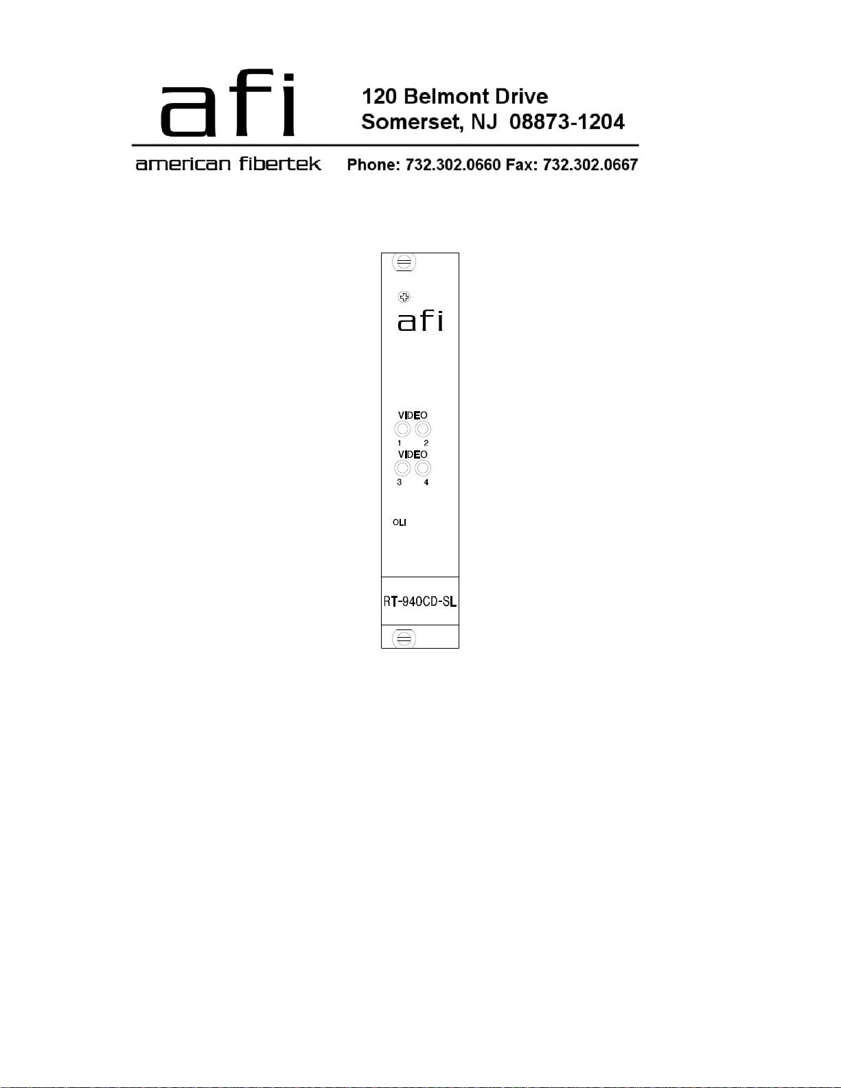
RT-940CD-SL
Four Channel Video Transmitter
With Diagnostic Interface
INSTALLATION AND OPERATION INSTRUCTIONS
INTRODUCTION
Thank you for purchasing your American Fibertek RT-940CD-SL singlemode four channel video
transmitter with diagnostic interface. Please take a few minutes to read these installation
instructions in order to obtain the maximum performance from this product.
FUNCTIONAL DESCRIPTION
The RT-940CD-SL operates as half of a transmitter / receiver pair for the transmission of four
channels of high performance 10 bit digital NTSC, PAL, RS170, or RS343 video signals. The
RT-940CD-SL is designed to operate with the RR-940CD-SL video receiver over one
singlemode fiber optic cable. The 940CD-SL Series product is designed to operate over an
optical loss budget range of 0 to 21 dB. Refer to the data sheets for detailed performance
specifications.
This unit is designed for rack mounting in the American Fibertek SR-20D/2 subrack. Slide in
rack mounting, detachable terminal blocks, and LED indicators provide for easy installation and
monitoring of video and optical power.
The RT-940CD-SL has a built in capability to be remotely monitored through the AFINETY
Remote Diagnostics System. A SR-20D/2 subrack and a RD-20D diagnostic card are required
to facilitate this feature. Please refer to the SR-20D/2 and RD-20D Instruction Manuals for
proper operation of this feature.
INSTALLATION
THE INSTALLATION OF THIS UNIT SHOULD BE MADE BY A QUALIFIED SERVICE
PERSON(S) AND MUST CONFORM TO ALL LOCAL CODES.
A maximum of seven 940CD-SL units are recommended in one subrack. Forced air movement
is required to dissipate heat in any installation containing seven or more 940CD-SL units in one
subrack.
2
 Loading...