

Page 1
© Copyright 2012, American Fibertek, Inc. 3-11-13 JPK
Bi-directional Multi-Protocol Data
And Bi-directional Contact Closure
Instruction Manual
Video Transmitter With
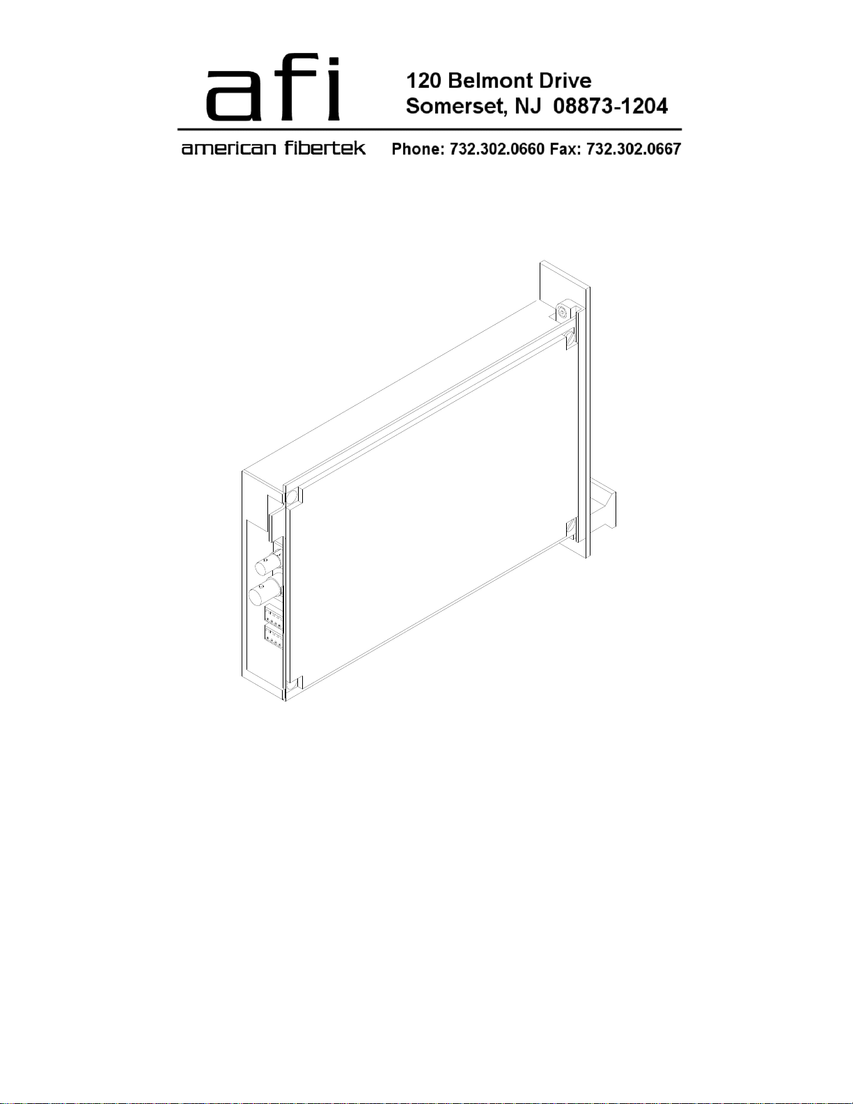
RT-915C
Page 2
INSTALLATION AND OPERATION INSTRUCTIONS
INTRODUCTION
Thank you for purchasing your American Fibertek RT-915C multimode video transmitter with bidirectional multi-protocol data and bi-directional contact closure. Please take a few minutes to read
these installation instructions in order to obtain the maximum performance from this product.
FUNCTIONAL DESCRIPTION
The RT-915C operates as half of a transmitter / receiver pair for the transmission of high performance
10 bit digital NTSC, PAL, RS170, or RS343 video signals. The RT-915C also supports two bidirectional data channels. These data channels are configured as follows:
Channel 1: RS485 (2 or 4 wire) data, RS422 data, RS232 data, or Manchester data
Channel 2: Contact Closure (dry)
NOTE: This unit is shipped with Channel 1 in the RS485 4-wire configuration. For other
configurations, please refer to the DATA CONFIGURATION section for changes to the default
switch settings.
The RT-915C is designed to operate with the MR-915C or RR-915C video receiver with bi-directional
data over one multimode fiber optic cable.
The RT-915C multiplexes a single video input signal along with up to two data signals into a high speed
serial data stream. This serial data stream modulates a laser at 1310 nm wavelength. The RT-915C
also detects and demultiplexes a return optical serial data stream signal containing up to two data
channels at 1550 nm wavelength. The 915 Series product is designed to operate over an optical loss
budget range of 0 to 12 dB when used on 62.5 um multimode fiber. The RT-915C will also operate on
50 um multimode fiber at a reduced loss budget range. Refer to the product specification sheet for
additional performance data.
The RS485 channel may be configured for 2-wire (half duplex) or 4-wire (full duplex) with or without
biasing. Switch selectable internal 120 ohm terminations are available for RS422 or RS485 data.
This unit is contained in a rugged aluminum housing with internal dc voltage regulation. The detachable
terminal blocks and LED indicators provide for easy installation and monitoring of video, data, and
optical power.
The RT-915C is designed for mounting as a modular stand alone unit. For a rack mounted version
please see the RT-915C.
2
Page 3
INSTALLATION
THIS INSTALLATION SHOULD BE MADE BY A QUALIFIED SERVICE PERSON AND SHOULD
CONFORM TO THE NATIONAL ELECTRICAL CODE, ANSI/NFPA 70 AND LOCAL CODES.
The unit slides into any open slot in the SR-20 or SR-20D subrack. Use a small screwdriver to push
and lock the two ¼ turn fasteners into place.
POWER SOURCE
Power to the unit is supplied by the subrack. Please refer to the SR-20/SR20D and PSR-2 instructions
for further details.
POWER CONNECTION
Power is supplied to the unit via a four finger backplane connector. The RT-915C can be inserted into
the subrack or removed from the subrack with power applied to the backplane.
FIBER CONNECTION
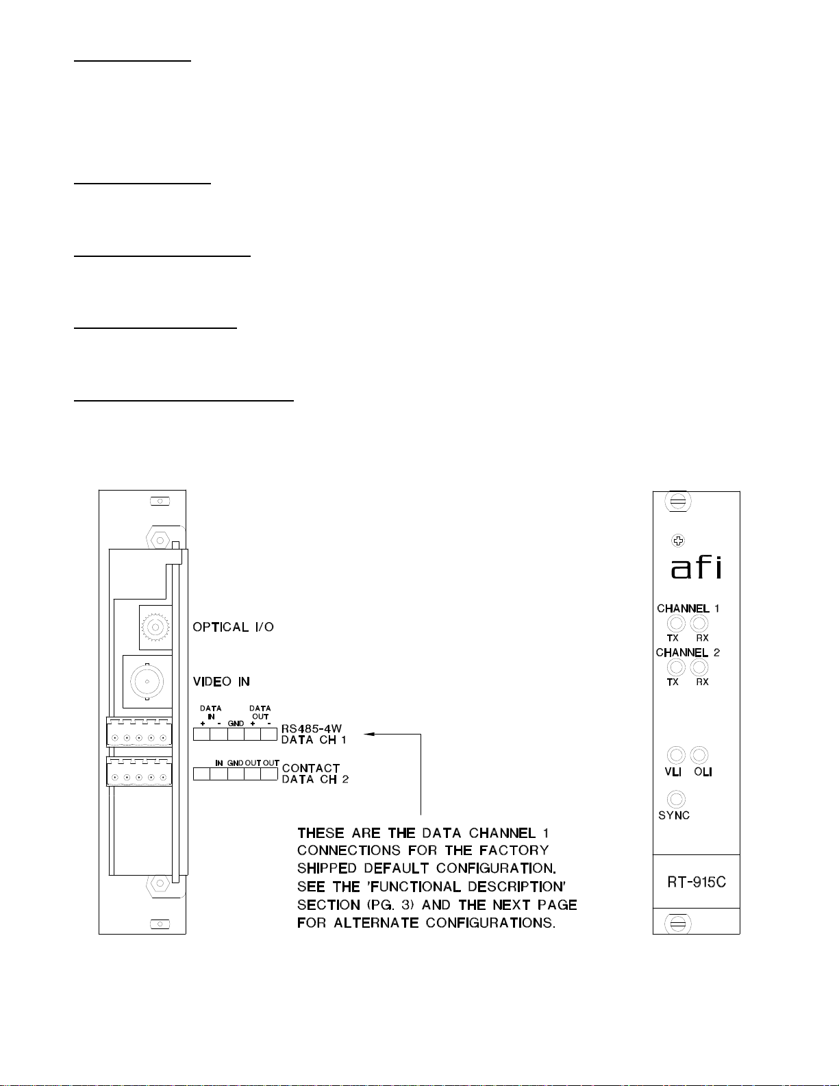
The fiber optic connection is made via a ST connector located on the back of the unit. Be sure to allow
sufficient room for the required minimum bend radius of the fiber cable used.
VIDEO INPUT CONNECTION
The video input connection is made via a BNC connector on the back of the unit. The video input
should be connected to an appropriate 75 base band video source such as a camera or a video
recorder output. For optimum performance the video cables should be the shortest length of coax
practical.
3
Page 4
DATA INPUT / OUTPUT CONNECTIONS
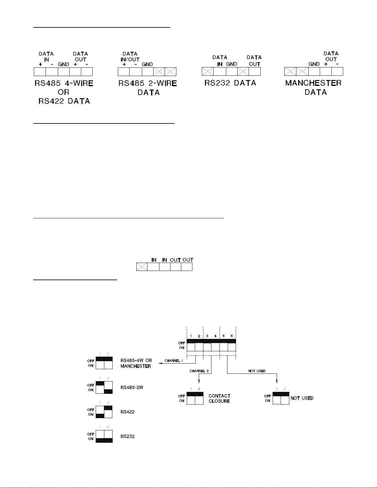
Data input and output connections are made via terminal blocks on the back of the unit. See the
drawings below for proper orientation of the input and output connections for Data Channel 1.
TYPICAL SYSTEM DATA CONNECTIONS
The RS422 or RS485 four wire interconnection between the RT-915C and the copper device to which it
is attached is based on industry standard EIA terminology for the transmission of electronic data
signals. Using this terminology, the driver of an electronic signal is labeled TX or Data Out.
Correspondingly, the receiver of an electronic signal is labeled RX or Data In. Following this standard,
the Data Out of the copper device is connected to the Data In of the RT-915C. The plus terminal of the
copper device is connected to the plus terminal of the RT-915C and the minus is connected to the
minus. The reverse flow of data from the RT-915C to the copper device follows the same pattern. Not
all manufactures follow standard EIA terminology. Consult the installation instructions for your copper
device if you are unsure which two wires are the drive (data out) wires and which two wires are the
receive (data in) wires.
CONTACT CLOSURE INPUT / OUTPUT CONNECTIONS
Contact Closure input and output connections are made via the bottom (DATA 2) terminal block on the
back of the unit. See the drawing below for proper orientation of input and output connections. Please
note that the far right pin on the connection drawing corresponds with the far right pin when looking at
the terminal block from the back of the unit.
DATA CONFIGURATION
NOTE: This unit is shipped in the following default configuration.
Channel 1: RS485 (4 wire) data
Channel 2: Contact Closure (dry)
For other configurations of Channel 1, please refer to the drawing below for changes to the default
switch settings. These configuration switches are located on the left side of the unit and can be
modified without opening the unit.
4
Page 5
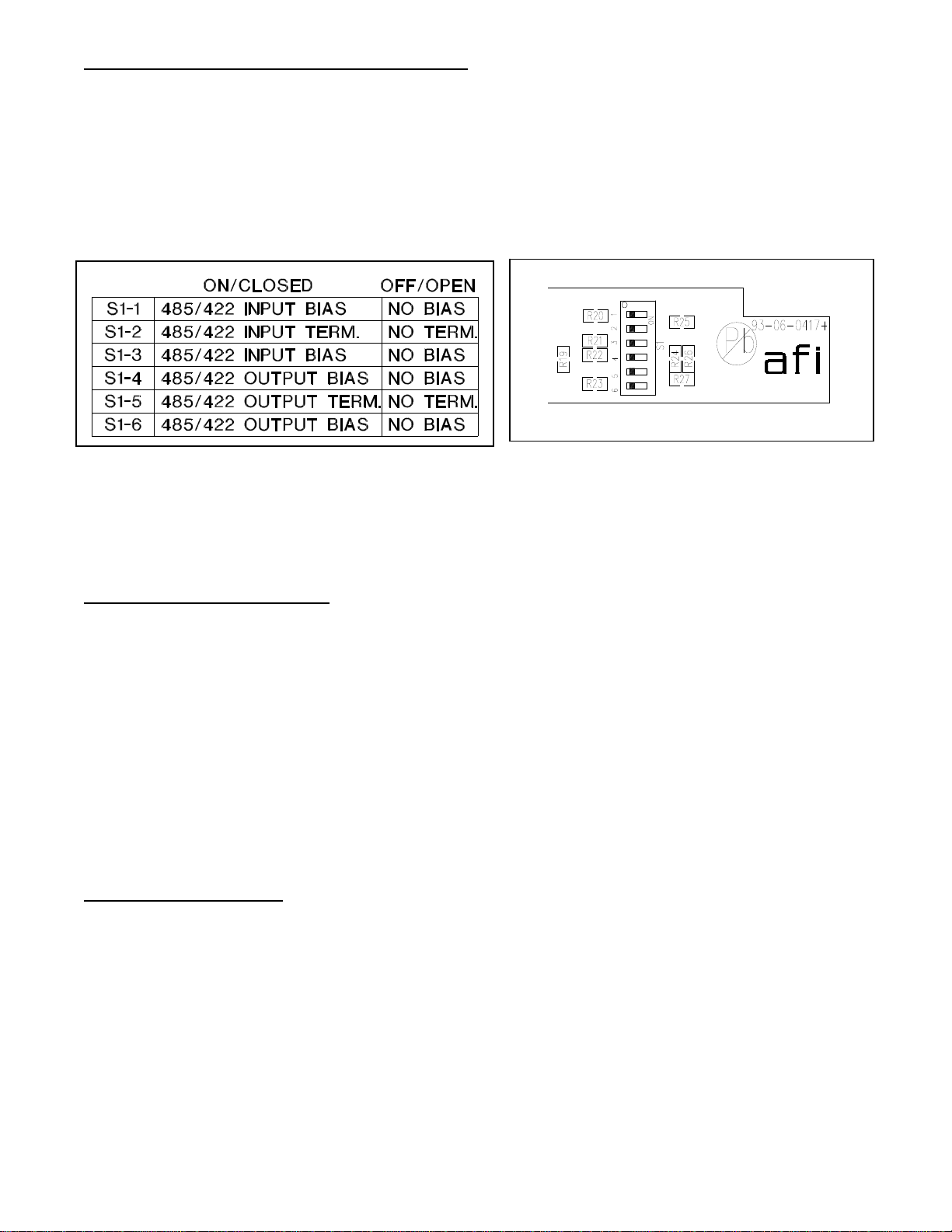
CHANNEL BIAS / TERMINATION SWITCHES
Switches are available internally that allow offset bias and termination features to be activated when
using RS485 data. These switches also allow termination features to be activated when using RS422
data. In order to reconfigure the RS485/422 channel, the module needs to be opened up. To open the
RT-915C, remove the end panel on the terminal block side and remove the screw on the bottom of the
module. Slide the PCB assembly out about half way. The configuration switch bank is located at the
lower right corner of PCB next to the data terminals (See drawing below).
The RT-915C is shipped with these switches in the off (down) position. When transmitting RS232 or
Manchester data, the bias and termination switches must remain in the off (down) position. The S1
switches correspond to channel 1. The chart below describes the layout of the S1 switch bank.
Please remember when using offset bias switches that they must be used in pairs. If switch # 1 is up
then switch # 3 must also be up. The same situation applies for switch # 4 and switch # 6. Also, if using
offset bias, it is important that the corresponding termination resistor switch be in the on (up) position.
Using offset bias without a termination on the line will cause communications to fail. An explanation
follows on general bias and termination guidelines.
RS485 DATA TERMINATION
The RS485 protocol is an expanded version of the original RS422 protocol. RS485 differs from RS422
in the ability of the transmitter devices to go into a high impedance (Hi-Z) state. This allows multiple
transmitter devices to reside on the same wire pair. The software must dictate a protocol that allows
only one device to transmit at any one time to prevent data crashes. In many cases the system head
end controller will continuously poll data from all remote devices. The remote devices all respond back
to the head end (one at a time) as they are addressed. The driver chips that are used in RS485
communications are capable of changing into their high impedance state very rapidly. On even short
lengths of wire there can exist a residual voltage after a driver circuit turns off. This can interfere with
circuits that are used to detect the Hi-Z state. It is very important that the copper communications lines
be terminated with resistors across the data wire pair. The best place to locate such resistors is at the
furthest electrical devices at the ends of the wire pair. For instance, if several RS485 devices are
connected in a daisy chain fashion, the wire connection would loop across all devices in a chain. The
furthest two points in the chain would need to be terminated.
OFFSET BIAS – RS485
The RS485 specification requires receivers to detect input signals down to 200mVp-p of voltage level.
In many cases this can cause systems to be sensitive to noise on the data wires. In an effort to
eliminate the effects of low levels of noise, some manufacturers of equipment that communicate using
RS485 have introduced a small voltage bias to the data lines. This is usually accomplished using a 470
Ohm resistance to +5V on the positive line and 470 Ohm resistance to ground on the negative line.
When used in conjunction with the appropriate termination resistors referred to in the previous section,
this introduces about a 300 mV offset, improving noise immunity.
5
Page 6
RT-915C STATUS INDICATORS
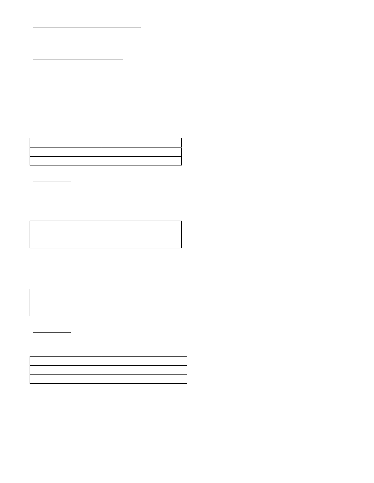
The RT-915C transmitter provides the following LED status indicators to aid in installation and
troubleshooting:
DATA TX/RX INDICATORS
DATA TX and DATA RX indicators are provided to monitor each of the two available data channels.
DATA 1 TX and RX correspond with the multi-protocol input/output of DATA CH 1. DATA 2 TX and RX
correspond with the contact closure input/output of DATA CH 2.
DATA 1 TX
A green LED indicator is provided to monitor the data coming in from the electrical interface, through
the RT-915C, and out onto the fiber. The intensity of this indicator will vary with input data patterns;
however in typical applications it will cycle on and off as data is transmitted. Data transmitted status
associated with this LED is summarized below.
DATA 1 TX LED Data Status
Green Data Flow Present
Off Data Flow Not Detected
DATA 1 RX
A green LED indicator is provided to monitor the data coming in from the fiber, through the RT-915C,
and out onto the electrical interface. The intensity of this indicator will vary with input data patterns;
however in typical applications it will cycle on and off as data is received. Data received status
associated with this LED is summarized below.
DATA 1 RX LED Data Status
Green Data Flow Present
Off Data Flow Not Detected
DATA 2 TX
A green LED indicator is provided to monitor the contact input from the electrical interface, through the
RT-915C, and out onto the fiber. Contact status associated with this LED is summarized below.
Data 2 TX LED Contact Status
Green Contact Input Closed
Off Contact Input Open
DATA 2 RX
A green LED indicator is provided to monitor the contact output from the fiber, through the RT-915C,
and out onto the electrical interface. Contact status associated with this LED is summarized below.
Data 2 RX LED Contact Status
Green Contact Output Closed
Off Contact Output Open
6
Page 7

VLI
A bi-color LED indicator is provided for the video input to the RT-915C. DC power and video status
associated with this LED is summarized below.
Video Presence LED DC Power Status Video Status
Green On Proper Input Video Present
Red On Input Video Not Detected
Off Off Check Power Supply
OLI
A bi-color LED indicator monitors the optical input power of the data signal that is being received at the
RT-915C from the MR-915C or the RR-915C. DC power and optical input status associated with this
LED are summarized below.
Optical Level Indicator DC Power Status Optical Status
Green On Proper Optical Input Power Present
Red On Optical Input Not Detected
Off Off Check Power Supply
SYNC
A bi-color LED indicator is provided to monitor the proper serialization of the electrical data stream
through the RT-915C and out onto the fiber. DC power and sync status associated with this LED is
summarized below.
Sync LED DC Power Status Sync Status
Green On Proper Data Stream Serialization Present
Red On Data Stream Serialization Not Detected
Off Off Check Power Supply
7
Page 8
LIFETIME WARRANTY INFORMATION
American Fibertek, Inc warrants that at the time of delivery the products delivered will be free of defects
in materials and workmanship. Defective products will be repaired or replaced at the exclusive option of
American Fibertek. A Return Material Authorization (RMA) number is required to send the products
back in case of return. All returns must be shipped prepaid. This warranty is void if the products have
been tampered with. This warranty shall be construed in accordance with New Jersey law and the
courts of New Jersey shall have exclusive jurisdiction over this contract. EXCEPT FOR THE
FOREGOING WARRANTY, THERE IS NO WARRANTY OF MERCHANTABILITY OR FITNESS FOR
A PARTICULAR PURPOSE OR OTHERWISE, EXPRESSED OR IMPLIED, WHICH EXTENDS
BEYOND THE WARRANTY SET FORTH IN THIS AGREEMENT. In any event, American Fibertek will
not be responsible or liable for contingent, consequential, or incidental damages. No agreement or
understanding, expressed or implied, except as set forth in this warranty, will be binding upon American
Fibertek unless in writing, signed by a duly authorized officer of American Fibertek.
SERVICE INFORMATION
There are no user serviceable parts inside the unit.
In the event that service is required to this unit, please direct all inquiries to:
American Fibertek, Inc. Phone: (877) 234-7200
120 Belmont Drive Phone: (732) 302-0660
Somerset, NJ 08873 FAX (732) 302-0667
E-mail: [email protected]
8
 Loading...