

American Fibertek RT-740C User Manual
10/01/2001 JPK
Instruction Manual
RT-740C
Four Channel Video Transmitter

INSTALLATION AND OPERATION INSTRUCTIONS
INTRODUCTION
Thank you for purchasing your American Fibertek RT-740C multimode four channel video
transmitter. Please take a few minutes to read these installation instructions in order to obtain
the maximum performance from this product.
FUNCTIONAL DESCRIPTION
The RT-740C operates as half of a transmitter / receiver pair for the transmission of four
channels of high performance 10 bit digital NTSC, PAL, RS170, or RS343 video signals. The
RT-740C is designed to operate with the MR-740C or RR-740C video receiver over one
multimode fiber optic cable.
The RT-740C multiplexes four video input signals into a high speed serial data stream. This
serial data stream modulates a laser at 1310 nm wavelength. The 740C Series product is
designed to operate over an optical loss budget range of 0 to 11 dB. Refer to the data sheets for
detailed performance specifications.
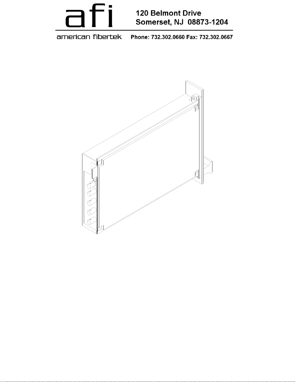
This unit is designed for rack mounting in any of the three American Fibertek subracks
available. The subrack model numbers are SR-20/1, SR-20R/1, and SR-20/2. Slide in rack
mounting and LED indicators provide for easy installation and monitoring of video and power.
The RT-740C is designed for rack mounting only. For a modular stand alone version please see
the MT-740C.
INSTALLATION
THE INSTALLATION OF THIS UNIT SHOULD BE MADE BY A QUALIFIED SERVICE
PERSON(S) AND MUST CONFORM TO ALL LOCAL CODES.
The unit slides into any open slot in the SR-20 subrack. Use a small screwdriver to push and
lock the two ¼ turn fasteners into place.
POWER SOURCE
Power to the unit is supplied by the subrack. Please refer to the SR-20 and PSR instructions for
further details.
POWER CONNECTION
Power is supplied to the unit via a four finger backplane connector. The RT-740C can be
inserted into the subrack or removed from the subrack with power applied to the backplane.
FIBER CONNECTION
The fiber optic connection is made via a ST connector located on the back of the unit. Be sure
to allow sufficient room for the required minimum bend radius of the fiber cable used.
VIDEO INPUT CONNECTIONS
The video input connections are made via BNC connectors on the right side of the unit. The
video input should be connected to an appropriate 75 baseband video source such as a
camera or a video recorder output. For optimum performance the video cables should be the
shortest length of coax practical.
2
 Loading...