

Page 1
© Copyright 2005, American Fibertek, Inc. 0922JD
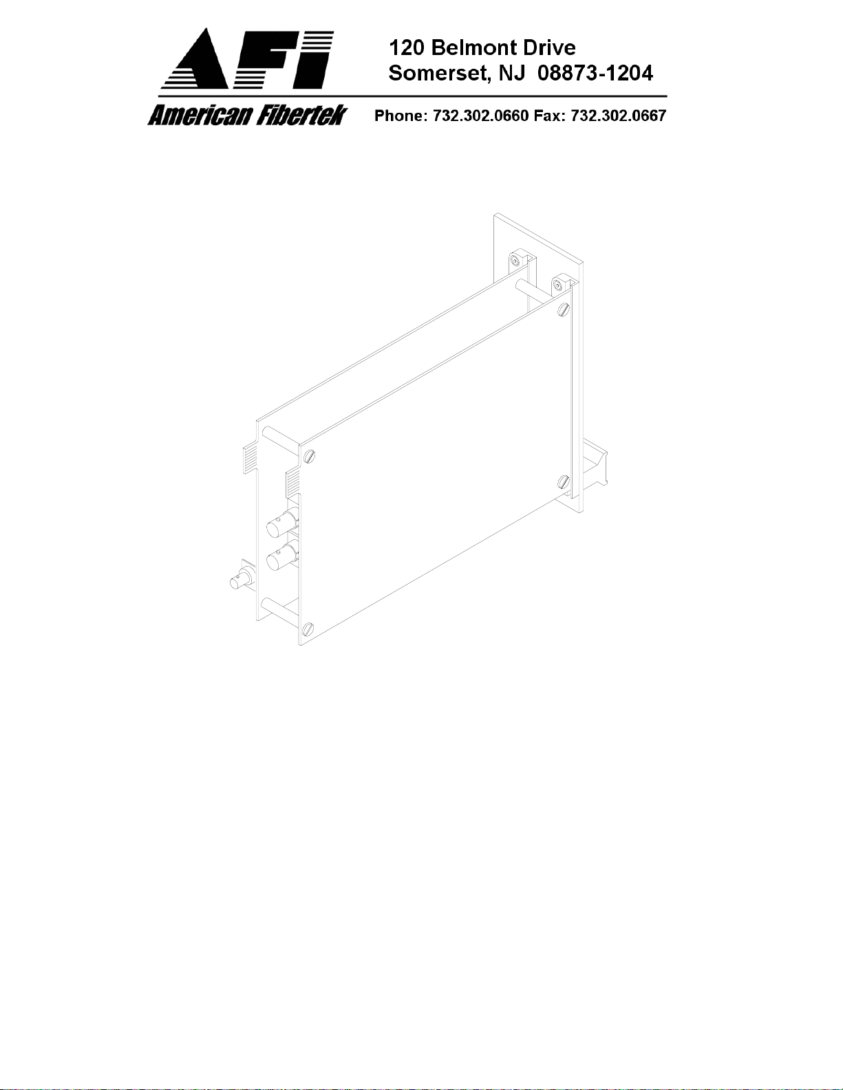
Two Channel Video Transmitter
Instruction Manual
RT-220C
Page 2
INSTALLATION AND OPERATION INSTRUCTIONS
INTRODUCTION
Thank you for purchasing your American Fibertek RT-220C multimode two channel video
transmitter. Please take a few minutes to read these installation instructions in order to obtain
the maximum performance from this product.
FUNCTIONAL DESCRIPTION
The RT-220C operates as half of a transmitter / receiver pair for the transmission of two
simultaneous, real time, baseband NTSC, PAL, RS170, or RS343 video signals. The RT-220C
is designed to operate with the MR-220C or RR-220C two channel video receiver over one
multimode fiber optic cable.
The RT-220C transmitter accepts up to two video inputs. Each video input modulates a
separate FM carrier frequency to allow the total of two video signals to be combined onto one
fiber. The 220C Series product is designed to operate over an optical loss budget range of 0 to
12 dB when used on 62.5 um multimode fiber. A maximum distance of 5km can be achieved as
long as the overall fiber bandwidth maintains a minimum of 150 MHz at 1300 nm. As an
example, if the system fiber has a 600 MHz-km modal bandwidth specification, the 220C will
operate over a distance up to 4 km. The RT-220C will also operate on 50 um multimode fiber at
a reduced loss budget range. Refer to the product specification sheet for additional performance
data.
This unit is designed for rack mounting in any of the four American Fibertek subracks available.
The subrack model numbers are SR-20/1, SR-20R/1, SR-20/2, and SR-20D/2. Slide in rack
mounting and LED indicators provide for easy installation and monitoring of video and dc power.
The RT-220C is designed for rack mounting only. For a modular stand alone version please see
the MT-220C.
INSTALLATION
THIS INSTALLATION SHOULD BE MADE BY A QUALIFIED SERVICE PERSON AND
SHOULD CONFORM TO THE NATIONAL ELECTRICAL CODE, ANSI/NFPA 70 AND LOCAL
CODES.
2
Page 3
The unit slides into any two adjacent open slots in the SR-20 subrack. Use a small screwdriver
to push and lock the four ¼ turn fasteners into place.
POWER SOURCE
Power to the unit is supplied by the subrack. Please refer to the SR-20 and PSR instructions for
further details.
POWER CONNECTION
Power is supplied to the unit via a four finger backplane connector. The RT-220C can be
inserted into the subrack or removed from the subrack with power applied to the backplane.
INPUT / OUTPUT CONNECTIONS
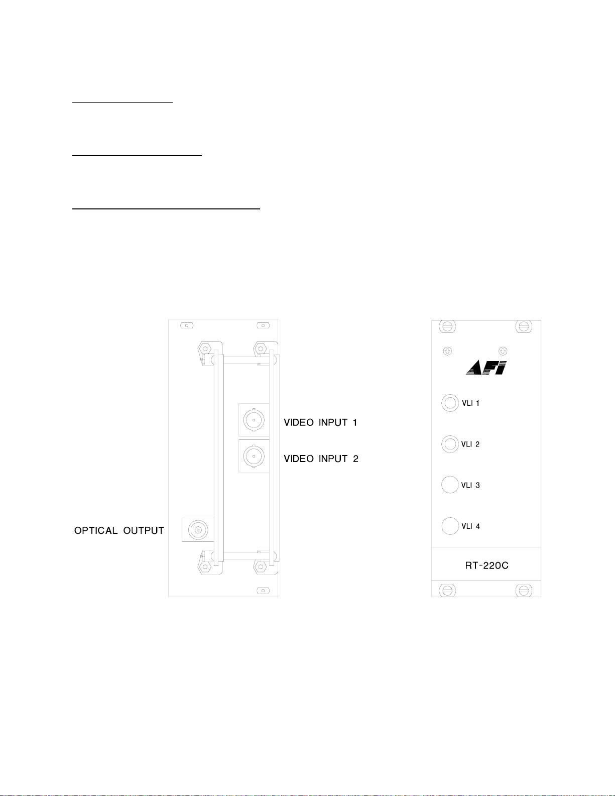
The fiber optic connection is made via a ST connector located on the back of the unit. Be sure
to allow sufficient room for the required minimum bend radius of the fiber cable used.
Video input connections are also located on the back of the unit. A BNC connector is provided
for each channel. The video inputs are connected to an appropriate 75Ω baseband video
source such as a camera or a video recorder output. For optimum performance the video cables
should be the shortest length of coax practical.
3
Page 4
RT-220C STATUS INDICATORS
The RT-220C transmitter provides the following LED status indicators to aid in installation and
troubleshooting:
VLI 1 AND VLI 2
A bi-color LED indicator is provided for each of the two video channel inputs. Video status
associated with each of these LEDs is summarized below.
Video Level Indicator Video Status
Green Proper Input Video Present
Red Input Video Not Detected
Off Check Power Supply
LIFETIME WARRANTY INFORMATION
American Fibertek, Inc warrants that at the time of delivery the products delivered will be free of
defects in materials and workmanship. Defective products will be repaired or replaced at the
exclusive option of American Fibertek. A Return Material Authorization (RMA) number is
required to send the products back in case of return. All returns must be shipped prepaid. This
warranty is void if the products have been tampered with. This warranty shall be construed in
accordance with New Jersey law and the courts of New Jersey shall have exclusive jurisdiction
over this contract. EXCEPT FOR THE FOREGOING WARRANTY, THERE IS NO WARRANTY
OF MERCHANTABILITY OR FITNESS FOR A PARTICULAR PURPOSE OR OTHERWISE,
EXPRESSED OR IMPLIED, WHICH EXTENDS BEYOND THE WARRANTY SET FORTH IN
THIS AGREEMENT. In any event, American Fibertek will not be responsible or liable for
contingent, consequential, or incidental damages. No agreement or understanding, expressed
or implied, except as set forth in this warranty, will be binding upon American Fibertek unless in
writing, signed by a duly authorized officer of American Fibertek.
SERVICE INFORMATION
There are no user serviceable parts inside the unit.
In the event that service is required to this unit, please direct all inquiries to:
American Fibertek, Inc. Phone: (877) 234-7200
120 Belmont Drive Phone: (732) 302-0660
Somerset, NJ 08873 FAX (732) 302-0667
E-mail: [email protected]
4
 Loading...