

American Fibertek RRX-81B User Manual
© Copyright 2009, American Fibertek, Inc. 0526JD
Contact Closure Transceiver
Instruction Manual
RRX-81B
Eight Channel

INSTALLATION AND OPERATION INSTRUCTIONS
INTRODUCTION
Thank you for purchasing your American Fibertek RRX-81B multimode contact closure transceiver.
Please take a few minutes to read these installation instructions in order to obtain the maximum
performance from this product.
FUNCTIONAL DESCRIPTION
The RRX-81B operates as half of a transceiver pair for the transmission of eight dry latching contact
closure signals. Four contact closures are transmitted in one direction on the link with the remaining
four contact closures transmitted in the opposite direction. It is designed to operate with the MTX-81B
or RTX-81B contact closure transceiver over one multimode fiber optic cable. The RRX-81B transceiver
has a user selectable switch that allows the contact outputs of the unit to be maintained unchanged
through loss of optical or electrical power at the RRX-81B. The RRX-81B transceiver also includes a
recessed button to clear all contacts to a default state.
The RRX-81B converts an optical input from the MTX-81B or RTX-81B into four contact closure outputs
using a 1310 nm wavelength detector. The RRX-81B also converts four contact closure inputs into an
optical output using a 1550 nm wavelength source. The RRX-81B operates on 50 um or 62.5 um
multimode fiber. The 81B Series product is designed to operate over an optical loss budget range of 0
to 12dB when using 62.5um fiber. Refer to the data sheets for detailed performance specifications.
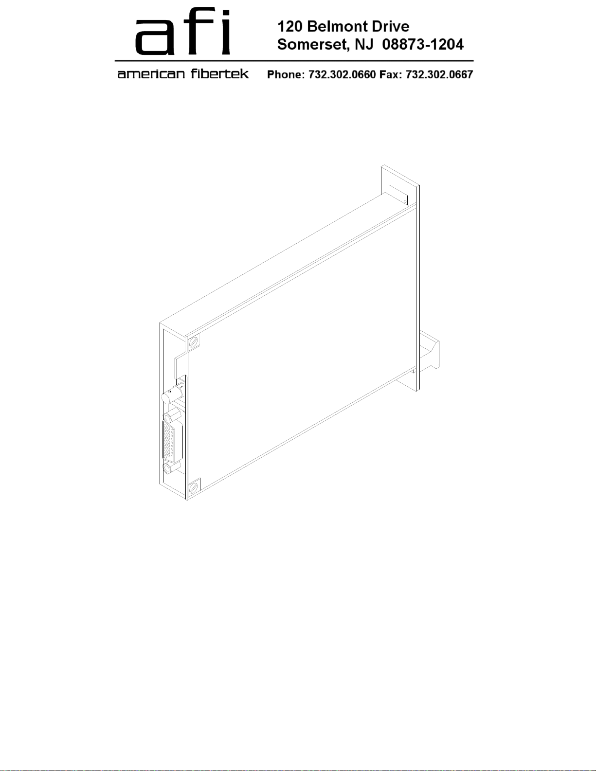
This unit is designed for rack mounting in either of two American Fibertek subracks. The subrack model
numbers are SR-20/2 or SR-20D/2. Slide in rack mounting, detachable terminal blocks, and LED
indicators provide for easy installation and monitoring of data and optical power. The RRX-81B is
designed for mounting as a rack mounted unit. For a stand alone version please see the MRX-81B.
INSTALLATION
THIS INSTALLATION SHOULD BE MADE BY A QUALIFIED SERVICE PERSON AND SHOULD
CONFORM TO THE NATIONAL ELECTRICAL CODE, ANSI/NFPA 70 AND LOCAL CODES.
The unit slides into any open slot in the SR-20 or SR-20D subrack. Use a small screwdriver to push
and lock the two ¼ turn fasteners into place.
POWER SOURCE
Power to the unit is supplied by the subrack. Please refer to the SR-20/SR-20D and PSR-2 instructions
for further details.
POWER CONNECTION
Power is supplied to the unit via a four finger backplane connector. The RRX-81B can be inserted into
the subrack or removed from the subrack with power applied to the backplane.
2
 Loading...