

Page 1
© Copyright 2006, American Fibertek, Inc. 1219JD
With Bi-directional RS485 Data
Instruction Manual
RRM-1485-2F8
Video Receiver
Page 2
Table of Contents
Functional Description ........................................................................3
Installation...........................................................................................3
Power Source .....................................................................................3
Power Connection...............................................................................3
Fiber Input / Output Connections........................................................4
Video Output Connection....................................................................4
RS485 Four Wire Input / Output Connections.....................................4
RS485 Two Wire Input / Output Connections.....................................5
Data Configuration..............................................................................5
Switch/Jumper Settings.......................................................................6
RRM-1485-2F8 Status LED Indicators................................................7
RS-485 Termination and Offset Bias Requirements...........................7
Warranty and Service Information ......................................................8
2
Page 3

INSTALLATION AND OPERATION INSTRUCTIONS
INTRODUCTION
Thank you for purchasing your American Fibertek RRM-1485-2F8 multimode video receiver with
RS485 transceiver. Please take a few minutes to read these installation instructions in order to
obtain the maximum performance from this product.
FUNCTIONAL DESCRIPTION
The RRM-1485-2F8 operates as half of a transmitter / receiver pair for the transmission of
baseband NTSC, PAL, RS170, or RS343 video signals and bi-directional RS485 data. It is
designed to operate with the MTM-1485-2F8 or RTM-1485-2F8 video transmitter with RS485
transceiver over two multimode fibers.
The RRM-1485-2F8 converts a FM modulated optical fiber input into a single video output and a
single RS485 output using an 850 nm wavelength detector. The RRM-1485-2F8 also converts
an electrical RS485 input signal into an optical RS485 output returning on a separate fiber using
an 850 nm wavelength source. This unit may be configured for two wire half duplex or four wire
full duplex electrical interfaces. The M1485-2F8 Series product is designed to operate over an
optical loss budget range of 0 to 12 dB. The RRM-1485-2F8 operates on 50 um or 62.5 um
multimode fiber. Refer to the data sheets for detailed performance specifications.
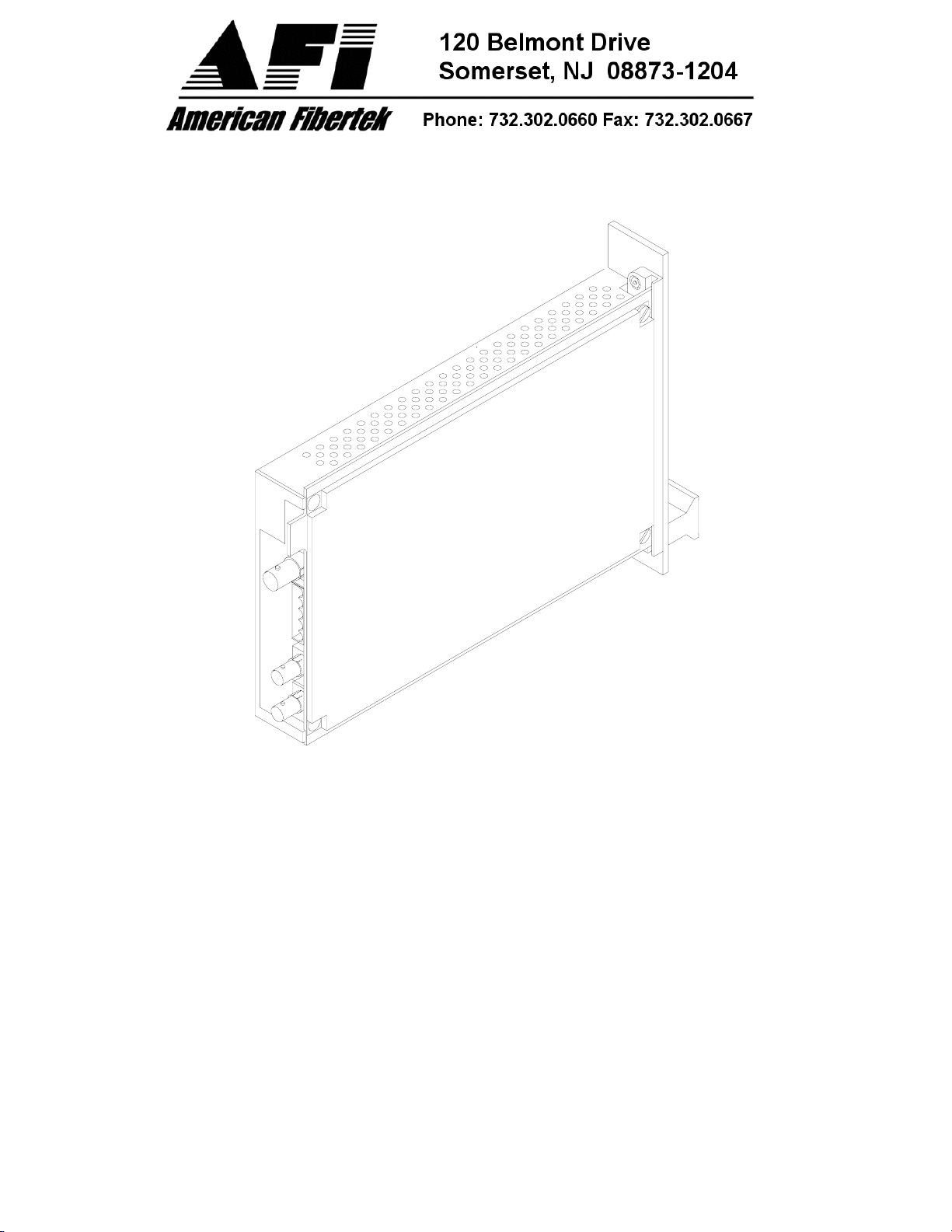
This unit is designed for rack mounting in any of the three American Fibertek subracks
available. The subrack model numbers are SR-20/1, SR-20R/1, and SR-20/2. Slide in rack
mounting and LED indicators provide for easy installation and monitoring of video, data, and
power.
The RRM-1485-2F8 is designed for rack mounting only. For a modular stand alone version
please see the MRM-1485-2F8.
INSTALLATION
THIS INSTALLATION SHOULD BE MADE BY A QUALIFIED SERVICE PERSON AND
SHOULD CONFORM TO THE NATIONAL ELECTRICAL CODE, ANSI/NFPA 70 AND LOCAL
CODES.
The unit slides into any open slot in the SR-20 subrack. Use a small screwdriver to push and
lock the two ¼ turn fasteners into place.
POWER SOURCE
Power to the unit is supplied by the subrack. Please refer to the SR-20 and PSR instructions for
further details.
POWER CONNECTION
Power is supplied to the unit via a four finger backplane connector. The RRM-1485-2F8 can be
inserted into the subrack or removed from the subrack with power applied to the backplane.
3
Page 4

FIBER INPUT / OUTPUT CONNECTIONS
The fiber optic connections are made via ST connectors located on the back of the unit. Be sure
to allow sufficient room for the required minimum bend radius of the fiber cable used. Please
note that Fiber Out on the RRM-1485-2F8 is connected to Fiber In on the MTM-1485-2F8 or
RTM-1485-2F8. The reverse flow follows the same orientation.
VIDEO OUTPUT CONNECTION
The video output connection is made via a BNC connector on the back of the unit. The 75Ω
video output can be looped through typical baseband video inputs of switchers, recorders and
other equipment as required. For proper operation, the output must be terminated with 75Ω. For
optimum performance the video cables should be the shortest length of coax practical.
RS485 FOUR WIRE INPUT / OUTPUT DATA CONNECTIONS
Data input/output connections are made via a terminal block on the back of the unit. An example
of the RS485 interconnection between the RRM-1485-2F8 unit and the copper device to which it
is attached is shown below. This illustration is based on industry standard EIA terminology for
the transmission of electronic data signals. Using this terminology, the driver of an electronic
signal is labeled TX or data out. Correspondingly, the receiver of an electronic signal is labeled
RX or data in. Not all manufactures follow standard EIA terminology. Consult the installation
instructions for your copper device if you are unsure which two wires are the drive (data out)
wires and which two wires are the receive (data in) wires.
Also, please note that in four wire installations Data In on the RRM-1485-2F8 becomes Data
Out on the MTM-1485-2F8 or RTM-1485-2F8 after going across the fiber. The reverse flow
follows the same orientation.
4
Page 5

RS485 TWO WIRE INPUT / OUTPUT DATA CONNECTIONS
Data input/output connections are made via a terminal block on the back of the unit. An example
of the RS485 interconnection between the RRM-1485-2F8 unit and the copper device to which it
is attached is shown below. This illustration is based on industry standard EIA terminology for
the transmission of electronic data signals.
DATA CONFIGURATION
The RRM-1485-2F8 is shipped from the factory in the RS485 4-wire configuration. In order
to configure the unit for RS485 two wire operation, the unit needs to be opened up and
several switch settings and jumper pins need to be modified using the internal
switch/jumper settings shown on the next page.
The RRM-1485-2F8 is shipped from the factory with internal data input and output 120
ohm terminations switched on. In order to remove the internal terminations, the unit
needs to be opened up and several switch settings need to be modified using the internal
switch/jumper settings shown on the next page.
See page 7 for an explanation of termination and offset bias requirements for RS485 data. To
open the RRM-1485-2F8, remove three screws on top cover to remove cover and access the
switch and jumper locations.
5
Page 6

6
Page 7

RRM-1485-2F8 STATUS INDICATORS
The RRM-1485-2F8 receiver provides the following LED status indicators to aid in installation
and troubleshooting:
OLI
A bi-color LED indicator monitors the optical input power of the video and data signal that is
being received at the RRM-1485-2F8 from the MTM-1485-2F8 or the RTM-1485-2F8. DC power
and optical input status associated with this LED are summarized below.
Optical Level Indicator DC Power Status Optical Status
Green On Proper Optical Input Power Present
Red On Optical Input Not Detected
Off Off Check Power Supply
DATA TX
A red LED indicator is provided to monitor the RS485 input data from the electrical interface,
through the RRM-1485-2F8, and out onto the fiber. The intensity of this indicator will vary with
input data patterns, however in typical applications it will cycle on and off as data is transmitted.
RS485 status associated with this LED is summarized below.
DATA TX LED RS485 Status
Red Data Flow Present
Off Data Flow Not Detected
DATA RX
A red LED indicator is provided to monitor the RS485 data coming in from the fiber, through the
RRM-1485-2F8, and out onto the electrical interface. The intensity of this indicator will vary with
input data patterns, however in typical applications it will cycle on and off as data is received.
RS485 status associated with this LED is summarized below.
DATA RX LED RS485 Status
Red Data Flow Present
Off Data Flow Not Detected
RS485 TERMINATIONS
The RS485 protocol is an expanded version of the original RS422 protocol. The RS485 protocol
is an expanded version of the original RS422 protocol. RS485 differs from RS422 in the ability
of the transmitter devices to go into a high impedance (Hi-Z) state. This allows multiple
transmitter devices to reside on the same wire pair. The software must dictate a protocol that
allows one device to transmit at any one time to prevent data crashes. Data wiring can use two
wires or four wires. Using two wires the system works in half duplex. This means that data is
exchanged between two points sequentially. When a four-wire system is used, the system may
be full duplex. In many cases the system head end controller will continuously poll data from all
remote devices. The remote devices all respond back to the head end (one at a time!) as they
are addressed. This property of the network rests solely in the hands of the software or
firmware.
7
Page 8

The driver chips used in RS485 communications are capable of changing into their high
impedance state very rapidly. On even short lengths of wire there can exist a residual voltage
after a driver circuit turns off. This can interfere with circuits that are used to detect the Hi-Z
state. It is very important that the copper communications lines be terminated with resistors
across the data wire pair. The best place to locate such resistors is at the furthest electrical
devices at the ends of the wire pair. For instance, if several RS485 devices are connected in a
daisy chain fashion, the wire connection would loop across all devices in a chain. The furthest
two points in the chain would need to be terminated. A termination resistor for RS485 input data
can be selected in the RRM-1485-2F8 using switch # 1. A termination resistor for RS485 output
data can be selected in the RRM-1485-2F8 using switch # 2.
OFFSET BIAS – RS485
The RS485 specification requires receivers to detect input signals down to 200mVp-p of voltage
level. In many cases this can cause systems to be sensitive to noise on the data wires. In an
effort to eliminate the effects of low levels of noise, some manufacturers of equipment that
communicate using RS485 have introduced a small voltage bias to the data lines. This is
usually accomplished using 470 Ohm resistance to +5V on the positive line and 470 Ohm
resistance to ground on the negative line. When used in conjunction with the appropriate
termination resistors referred to in the previous section, this introduces about a 300 mV offset,
improving noise immunity.
Offset bias for RS485 can be applied on the RRM-1485-2F8 by setting switch # 3 and switch # 4
on. Please note that these switches work as a set and must be either both on or both off. In a
majority of cases, bias will not be required and these switches should remain in the off position.
If using offset bias, it is important that termination resistor switch # 2 be on (applied) position.
Using offset bias without a termination on the line will cause communications to fail.
LIFETIME WARRANTY INFORMATION
American Fibertek, Inc warrants that at the time of delivery the products delivered will be free of
defects in materials and workmanship. Defective products will be repaired or replaced at the
exclusive option of American Fibertek. A Return Material Authorization (RMA) number is
required to send the products back in case of return. All returns must be shipped prepaid. This
warranty is void if the products have been tampered with. This warranty shall be construed in
accordance with New Jersey law and the courts of New Jersey shall have exclusive jurisdiction
over this contract. EXCEPT FOR THE FOREGOING WARRANTY, THERE IS NO WARRANTY
OF MERCHANTABILITY OR FITNESS FOR A PARTICULAR PURPOSE OR OTHERWISE,
EXPRESSED OR IMPLIED, WHICH EXTENDS BEYOND THE WARRANTY SET FORTH IN
THIS AGREEMENT. In any event, American Fibertek will not be responsible or liable for
contingent, consequential, or incidental damages. No agreement or understanding, expressed
or implied, except as set forth in this warranty, will be binding upon American Fibertek unless in
writing, signed by a duly authorized officer of American Fibertek.
SERVICE INFORMATION
There are no user serviceable parts inside the unit.
In the event that service is required to this unit, please direct all inquiries to:
American Fibertek, Inc. Phone: (877) 234-7200
120 Belmont Drive Phone: (732) 302-0660
Somerset, NJ 08873 FAX (732) 302-0667
E-mail: techinfo@americanfibertek.com
8
 Loading...