

American Fibertek RRM-1485 User Manual
Instruction Manual
RRM-1485
Video Receiver
With Bi-directional RS485 Data
© Copyright 2005, American Fibertek, Inc. 0209JD

INSTALLATION AND OPERATION INSTRUCTIONS
INTRODUCTION
Thank you for purchasing your American Fibertek RRM-1485 multimode video receiver
with RS485 transceiver. Please take a few minutes to read these installation instructions
in order to obtain the maximum performance from this product.
FUNCTIONAL DESCRIPTION
The RRM-1485 operates as half of a transmitter / receiver pair for the transmission of
baseband NTSC, PAL, RS170, or RS343 video signals and bi-directional RS485 data. It
is designed to operate with the MTM-1485 or RTM-1485 video transmitter with RS485
transceiver over a single multimode fiber optic cable.
The RRM-1485 converts a FM modulated optical fiber input into a single video output
and a single RS485 output using a 1300 nm wavelength detector. The RRM-1485 also
converts an electrical RS485 input signal into an optical RS485 output returning on the
same fiber using an 850 nm wavelength source. This unit may be configured for two
wire half duplex or four wire full duplex electrical interfaces. The M1485 Series product
is designed to operate over an optical loss budget range of 0 to 12 dB. The RRM-1485
operates on 50 um or 62.5 um multimode fiber. Refer to the data sheets for detailed
performance specifications.
This unit is designed for rack mounting in any of the three American Fibertek subracks
available. The subrack model numbers are SR-20/1, SR-20R/1, and SR-20/2. Slide in
rack mounting and LED indicators provide for easy installation and monitoring of video
and power.
The RRM-1485 is designed for rack mounting only. For a modular stand alone version
please see the MRM-1485.
INSTALLATION
THE INSTALLATION OF THIS UNIT SHOULD BE MADE BY A QUALIFIED SERVICE
PERSON(S) AND MUST CONFORM TO ALL LOCAL CODES.
The unit slides into any open slot in the SR-20 subrack. Use a small screwdriver to push
and lock the two ¼ turn fasteners into place.
POWER SOURCE
Power to the unit is supplied by the subrack. Please refer to the SR-20 and PSR
instructions for further details.
POWER CONNECTION
Power is supplied to the unit via a four finger backplane connector. The RRM-1485 can
be inserted into the subrack or removed from the subrack with power applied to the
backplane.
2
FIBER CONNECTION
The fiber optic connection is made via a ST connector located on the back of the unit.
Be sure to allow sufficient room for the required minimum bend radius of the fiber cable
used.
VIDEO OUTPUT CONNECTION
The video output connection is made via a BNC connector on the back of the unit. The
75Ω video output can be looped through typical baseband video inputs of switchers,
recorders and other equipment as required. For proper operation, the output must be
terminated with 75Ω. For optimum performance the video cables should be the shortest
length of coax practical.
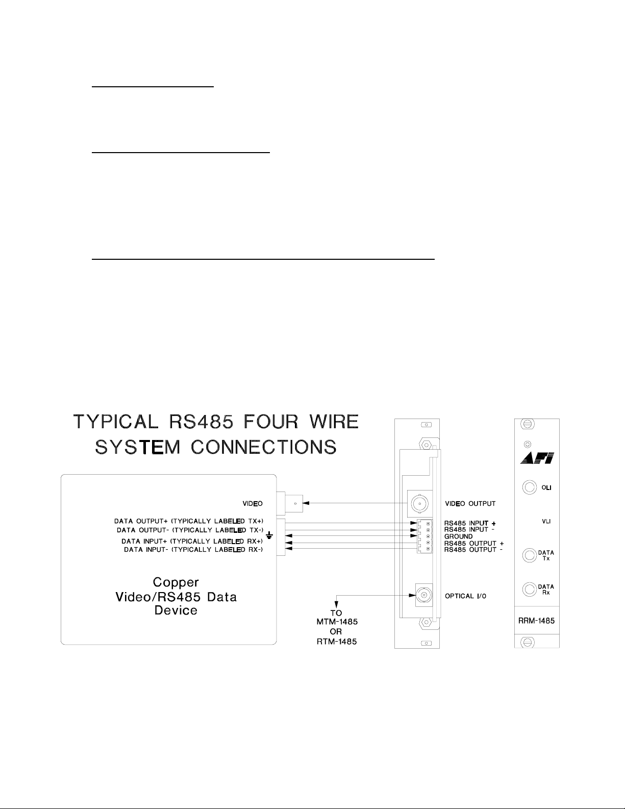
RS485 FOUR WIRE INPUT / OUTPUT DATA CONNECTIONS
Data input/output connections are made via a terminal block on the back of the unit. An
example of the RS485 interconnection between the RRM-1485 unit and the copper
device to which it is attached is shown below. This illustration is based on industry
standard EIA terminology for the transmission of electronic data signals. Using this
terminology, the driver of an electronic signal is labeled TX or data out. Correspondingly,
the receiver of an electronic signal is labeled RX or data in. Not all manufactures follow
standard EIA terminology. Consult the installation instructions for your copper device if
you are unsure which two wires are the drive (data out) wires and which two wires are
the receive (data in) wires.
3
 Loading...