

Page 1
© Copyright 2007, American Fibertek, Inc. 0413JD
Forty-Eight Channel Video Multiplexer
With Bi-directional Ethernet Data
Conversion Addendum
RT-94845SL
RR-94845SL
Page 2

INSTALLATION AND OPERATION INSTRUCTIONS
INTRODUCTION
Thank you for purchasing your American Fibertek Series 94845SL conversion kit to modify your
94885SL singlemode forty-eight channel video multiplexer to include bi-directional Ethernet
data. Please take a few minutes to read these installation instructions in order to obtain the
maximum performance from this product.
FUNCTIONAL DESCRIPTION
The 94845SL Series units operate as a transmitter / receiver pair for the digital transmission of
forty-eight simultaneous NTSC or PAL video signals along with one channel of bi-directional
Ethernet data over one singlemode fiber optic cable. The Ethernet data channel in this
application will be connected on each end to an N-PORT-5630-8 multiplexer which will combine
eight RS485 data channels into one Ethernet channel for transmission over the fiber. An autoconfigure feature in the N-PORT-5630-8 will eliminate the need to modify the external switch
setting on the 45 series units that select MDI or MDIX connections.
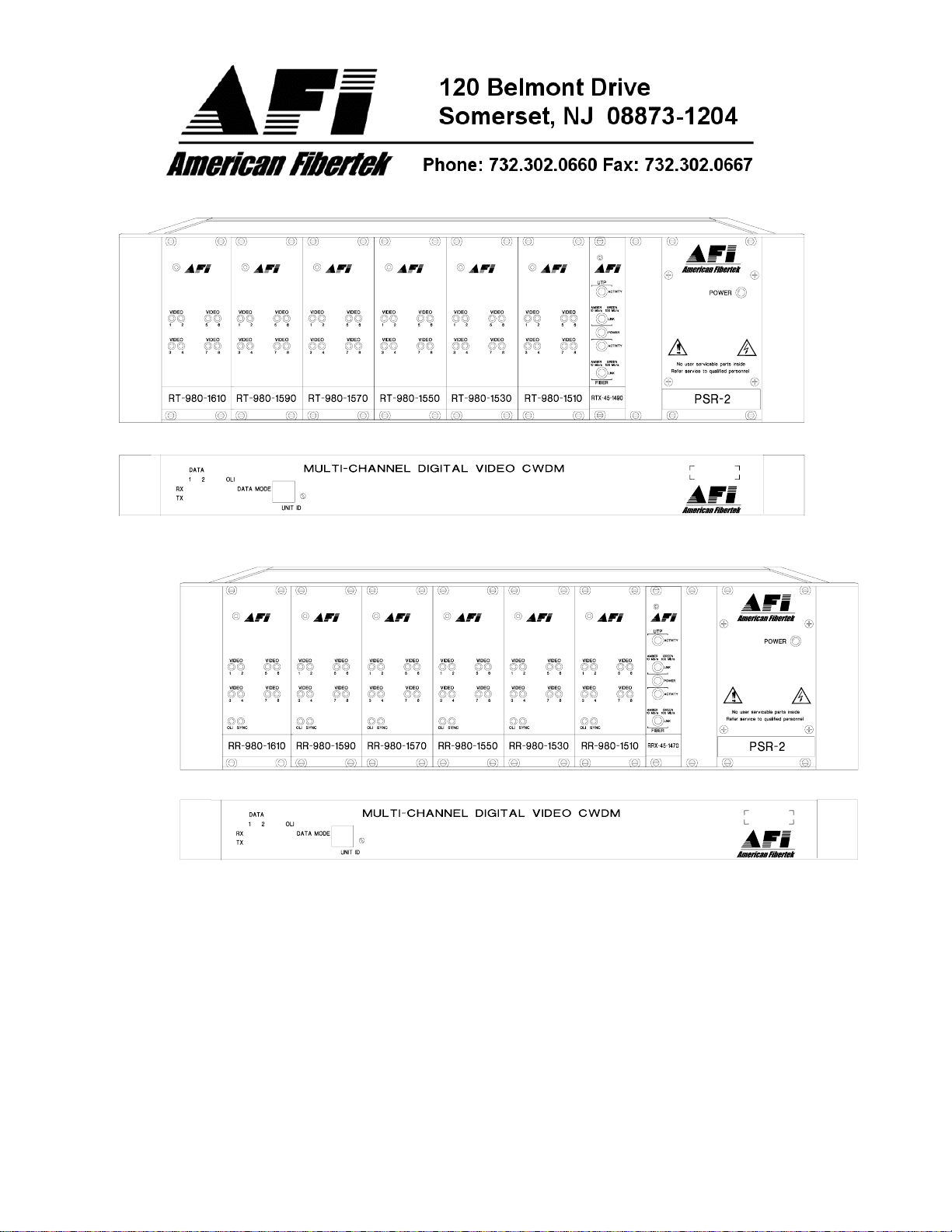
RT-94845SL CONVERSION COMPONENTS
The RT-94845SL conversion requires the following components:
1) RTX-45-1490 2) PCSC/UPC-0.3
1) MTX-CWDM-8 1) BPS-1
1) N-PORT-5630-8 1) RJ45 / RJ45 cable ) RJ45 to RJ12 camera cables
RR-94845SL CONVERSION COMPONENTS
The RR-94845SL conversion requires the following components:
1) RRX-45-1470 2) PCSC/UPC-0.3
1) MRX-CWDM-8 1) BPS-1
1) N-PORT-5630-8 1) RJ45 / RJ45 cable 8) RJ45 to RJ12 matrix cables
INSTALLATION
THIS INSTALLATION SHOULD BE MADE BY A QUALIFIED SERVICE PERSON AND
SHOULD CONFORM TO THE NATIONAL ELECTRICAL CODE, ANSI/NFPA 70 AND LOCAL
CODES.
2
Page 3

SYSTEM CONFIGURATION AND CONNECTIONS
Please refer to the 94845SL Instruction Manual included with this unit for proper configuration
and connections to this unit.
PREPARATION OF RT-94885SL UNIT
To begin the conversion of the RT-94885SL to a RT-94845SL, remove the six patchcords
connecting the RT-980 units to the CWDM at the rear of the rack. Save the patchcords, they will
be reused for the RT-94845SL. Disconnect the power cord and the fiber connection to the
CWDM from the fiber infrastructure and remove the MTX-CWDM-8-MPD. The MTX-CWDM-8MPD will need to be returned to AFI using packaging from the replacement CWDM sent as part
of this kit. From the front of the subrack, remove the BPS-2 blank plate from the left end of the
rack. Then move each of the RT-980 units one double slot to the left with the RT-980-1610 at
the leftmost side of the SR-20 subrack. This may require temporarily disconnecting the eight
coax cables attached to each unit.
INSTALATION OF RT-94845SL CONVERSION COMPONENTS
Following the drawings in the RT-94845SL Instruction Manual, insert the RTX-45-1490 into the
open slot next to the RT-980-1510. Install the BPS-1 blank plate over the remaining open slot in
the subrack. Install the MTX-CWDM-8 in the location previously occupied by the MTX-CWDM-8MPD. Use the six original patchcords along with two new patchcords from the conversion kit to
connect the RT-980 units and the RTX-45 unit to the CWDM.
ADDITION OF NPORT COMPONENTS TO RT-94845SL
For a complete description of the NPORT multiplexer unit, please refer to the informational CD
from NPORT included with this kit. Either of the NPORT multiplexers can be mounted directly
below the MTX-CWDM-8 or next to source of the eight RS485 data outputs, whichever is more
convenient to the application. Power for the NPORT units is generated by an internal power
supply which accepts universal line voltage. Any mains supply from 100 to 240 VAC, 50 to 60
Hz, may be used without modification or adjustment. A universal power connector is provided
on the rear of the unit to facilitate connection to the power mains.
NPORT MENU CONFIGURATION
The NPORT units supplied for this application have been pre-configured at the AFI factory.
These settings are designed for a point to point Ethernet connection between the NPORT and
the 45 series unit. The NPORT unit with an IP address of 192.168.10.148 is configured as
‘Master’, the NPORT unit with an IP address of 192.168.10.149 is set as ‘Slave’. The RS485
ports are set to communicate with the default Panasonic Matrix camera control values of 8 data
bits, 1 stop bit, no parity, and 9600 baud. To change these settings, please refer to the NPORT
informational CD.
RS485 DATA INPUT / OUTPUT CONNECTIONS
An RJ45 to RJ12 cable (labeled ‘CAMERA’) is supplied to connect each of the eight Serial Ports
on the back of the NPORT unit to the RS485 connection on each camera dome. See the
drawing on the next page for the location of the eight RS485 serial ports on the NPORT unit.
ETHERNET DATA INPUT / OUTPUT CONNECTIONS
A standard RJ45 cable is supplied in the conversion kit to connect the LAN port of the NPORT
unit to the Ethernet connection on the RTX-45-1490. Any standard RJ45 cable can be
substituted for this cable if the supplied cable is not long enough.
3
Page 4

NPORT
PREPARATION AND INSTALATION OF RR-94845SL CONVERSION COMPONENTS
Using the 94845SL Instruction Manual for guidance, the RR-94845SL is configured in a similar
manner as the RT-94845SL. Be sure to confirm the CWDM being used for the RR-94845SL is
the MRX-CWDM-8 and the 45 series card being used is the RRX-45-1470. Note that there is a
difference in the fiber patchcord configuration between the RRX-45-1470 and the RTX-45-1490
previously installed. Also note that the RJ45 to RJ12 cables used on the RR-9485SL are
labeled ‘MATRIX’.
NPORT STATUS INDICATORS
Along with a front panel LED that displays the IP address of the unit, the NPORT multiplexer
provides the following LED status indicators for each of its eight ports to aid in installation and
troubleshooting:
NPORT
PORT TX
A green LED indicator is provided to monitor the RS485 data output from the unit onto the
Ethernet link. The intensity of this indicator will vary with input data patterns, however in typical
applications it will cycle on and off as data is transmitted. RS485 status associated with this
LED is summarized below.
DATA TX LED RS485 Status
Green Data Flow Present
Off Data Flow Not Detected
PORT RX
An amber LED indicator is provided to monitor the RS485 data input into the NPORT unit from
the RS485 link. The intensity of this indicator will vary with input data patterns, however in
typical applications it will cycle on and off as data is transmitted. RS485 status associated with
this LED is summarized below.
DATA RX LED RS485 Status
Amber Data Flow Present
Off Data Flow Not Detected
Please see the NPORT informational CD included with this conversion kit if a more detailed
explanation of these status indicators is required.
4
 Loading...