

American Fibertek RR-915C-SL User Manual
© Copyright 2011, American Fibertek, Inc. 0313JPK
Bi-directional Multi-Protocol Data
And Bi-directional Contact Closure
Instruction Manual
Video Receiver With
RR-915C-SL
INSTALLATION AND OPERATION INSTRUCTIONS
INTRODUCTION
Thank you for purchasing your American Fibertek RR-915C-SL multimode video receiver with bidirectional multi-protocol data and bi-directional contact closure. Please take a few minutes to read
these installation instructions in order to obtain the maximum performance from this product.
FUNCTIONAL DESCRIPTION
The RR-915C-SL operates as half of a transmitter / receiver pair for the transmission of high
performance 10 bit digital NTSC, PAL, RS170, or RS343 video signals. The RR-915C-SL also supports
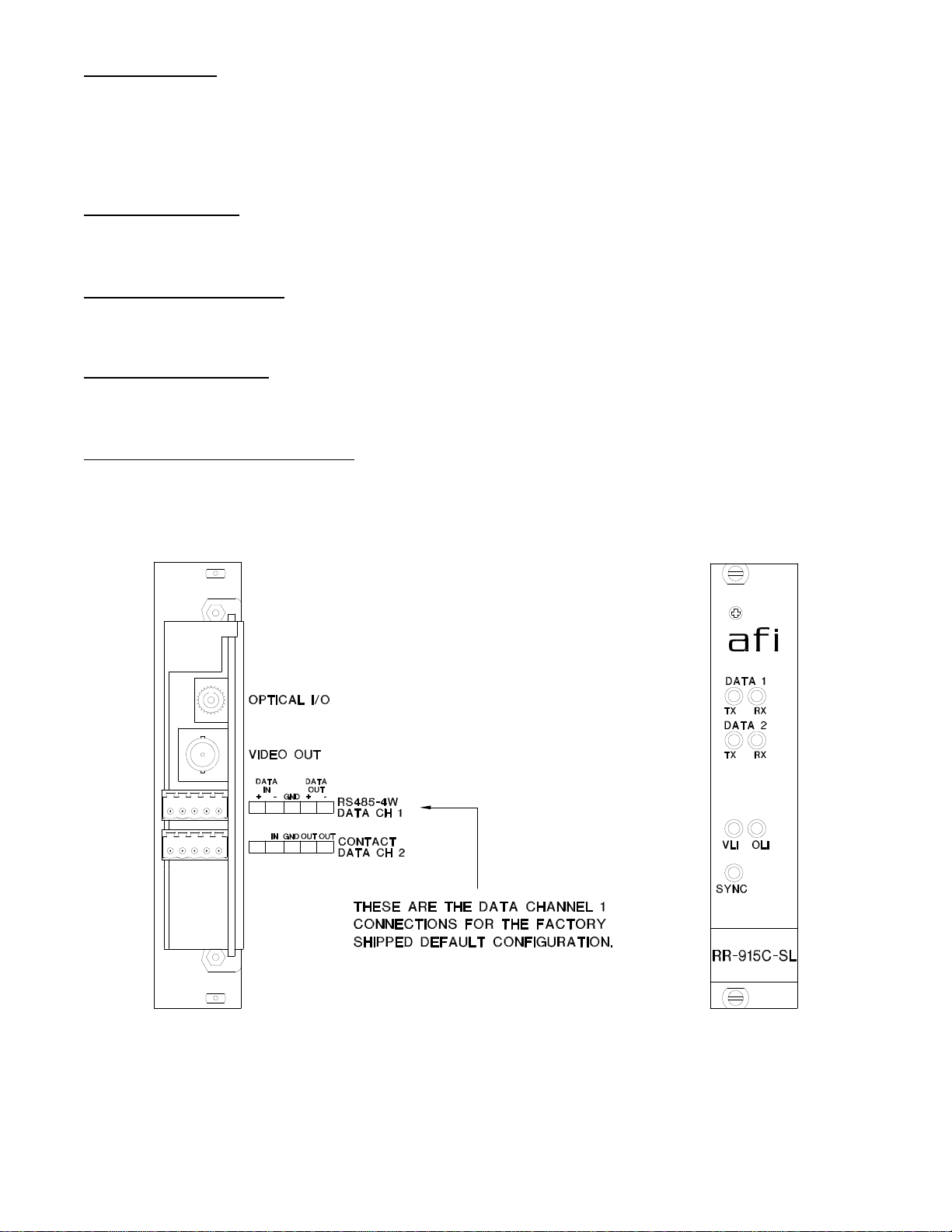
two bi-directional data channels. These data channels are configured as follows:
Channel 1: RS485 (2 or 4 wire) data, RS422 data, RS232 data, or Manchester data
Channel 2: Contact Closure (dry)
NOTE: This unit is shipped with Channel 1 in the RS485 4-wire configuration. For other
configurations, please refer to the DATA CONFIGURATION section for changes to the default
switch settings.
The RR-915C-SL is designed to operate with the MT-915C-SL or RT-915C-SL video transmitter with bidirectional data over one multimode fiber optic cable.
The RR-915C-SL multiplexes up to two data signals into a high speed serial data stream. This serial
data stream modulates a laser at 1550 nm wavelength. The RR-915C-SL also detects and
demultiplexes a return optical serial data stream signal containing a single video input signal along with
up to two data channels at 1310 nm wavelength. The 915C-SL Series product is designed to operate
over an optical loss budget range of 0 to 21 dB when used on 9 um singlemode fiber. Refer to the
product specification sheet for additional performance data.
The RS485 channel may be configured for 2-wire (half duplex) or 4-wire (full duplex) with or without
biasing. Switch selectable internal 120 ohm terminations are available for RS422 or RS485 data.
This unit is designed for rack mounting in either of two American Fibertek subracks available. The
subrack model numbers are SR-20/2 or SR-20D/2. Slide in rack mounting, detachable terminal blocks,
and LED indicators provide for easy installation and monitoring of video, data, and optical power.
The RR-915C-SL is designed for rack mounting only. For a modular stand alone version please see the
MR-915C-SL.
2
INSTALLATION
THIS INSTALLATION SHOULD BE MADE BY A QUALIFIED SERVICE PERSON AND SHOULD
CONFORM TO THE NATIONAL ELECTRICAL CODE, ANSI/NFPA 70 AND LOCAL CODES.
The unit slides into any open slot in the SR-20 or SR-20D subrack. Use a small screwdriver to push
and lock the two ¼ turn fasteners into place.
POWER SOURCE
Power to the unit is supplied by the subrack. Please refer to the SR-20/SR20D and PSR-2 instructions
for further details.
POWER CONNECTION
Power is supplied to the unit via a four finger backplane connector. The RR-915C-SL can be inserted
into the subrack or removed from the subrack with power applied to the backplane.
FIBER CONNECTION
The fiber optic connection is made via a ST connector located on the back of the unit. Be sure to allow
sufficient room for the required minimum bend radius of the fiber cable used.
VIDEO OUTPUT CONNECTION
The video output connection is made via a BNC connector on the back of the unit. The 75 video
output can be looped through typical baseband video inputs of switchers, recorders and other
equipment as required. For proper operation, the output must be terminated with 75. For optimum
performance the video cables should be the shortest length of coax practical.
3
 Loading...