

American Fibertek RR-440C-E User Manual
© Copyright 2005, American Fibertek, Inc. 1003JD
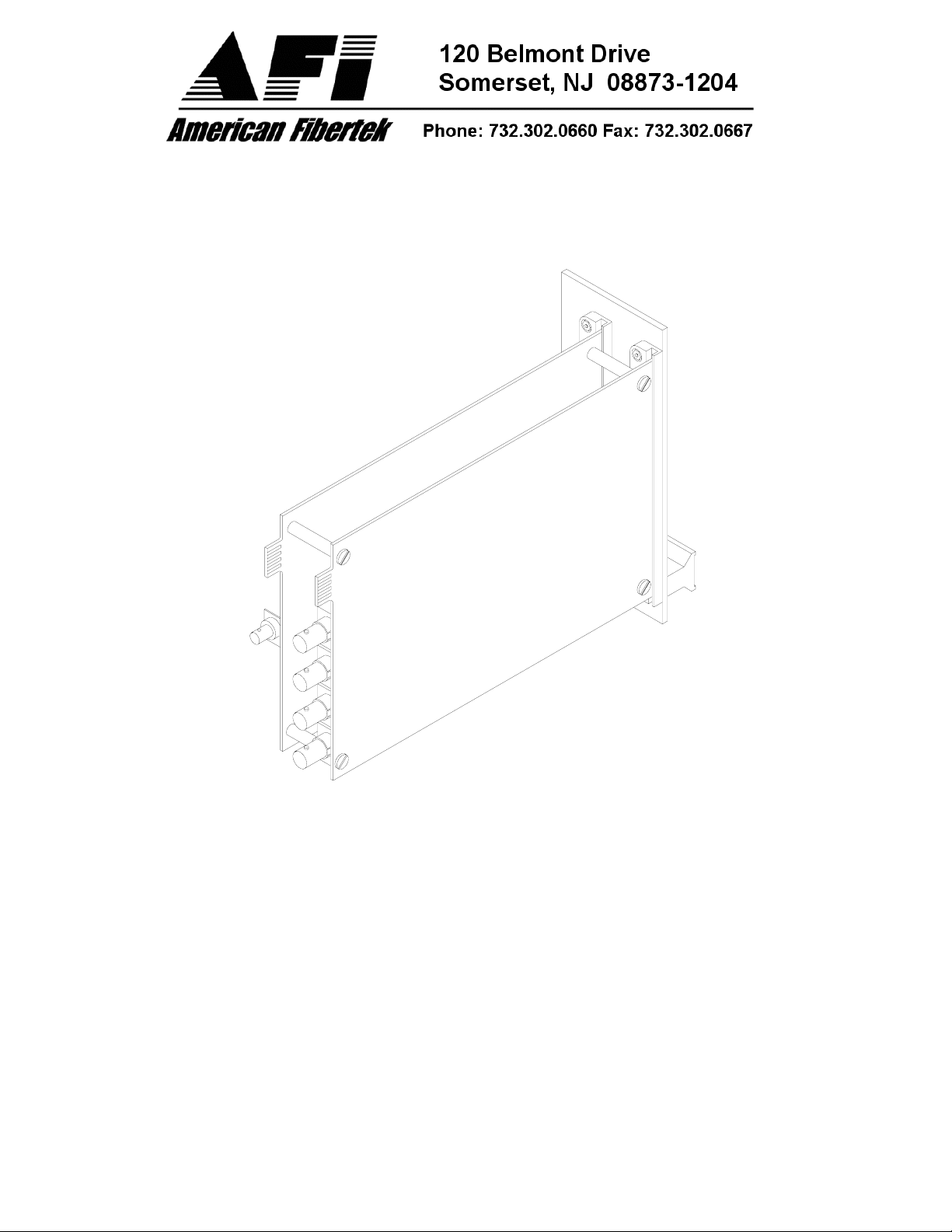
Four Channel Video Receiver
Instruction Manual
RR-440C-E

INSTALLATION AND OPERATION INSTRUCTIONS
INTRODUCTION
Thank you for purchasing your American Fibertek RR-440C-E multimode four channel video
receiver. Please take a few minutes to read these installation instructions in order to obtain the
maximum performance from this product.
FUNCTIONAL DESCRIPTION
The RR-440C-E operates as half of a transmitter / receiver pair for the transmission of four
simultaneous, real time, baseband NTSC, PAL, RS170, or RS343 video signals. The RR-440CE is designed to operate with the MT-440C-E or RT-440C-E video transmitter over one
multimode fiber optic cable.
The RR-440C-E receiver converts a single optical input into a maximum of four video outputs.
The 440C-E Series product is designed to operate over an optical loss budget range of 5 to 16
dB when used on 62.5 um multimode fiber. A maximum distance of 8km can be achieved as
long as the system fiber cable used has a modal bandwidth specification of 600 MHz-km or
higher. Lower bandwidth specifications will result in a reduced maximum distance. The RR440C-E will also operate on 50 um multimode fiber at a reduced loss budget range. Refer to the
product specification sheet for additional performance data.
This unit is designed for rack mounting in any of the four American Fibertek subracks available.
The subrack model numbers are SR-20/1, SR-20R/1, SR-20/2, and SR-20D/2. Slide in rack
mounting and LED indicators provide for easy installation and monitoring of video and dc power.
The RR-440C-E is designed for rack mounting only. For a modular stand alone version please
see the MR-440C-E.
INSTALLATION
THIS INSTALLATION SHOULD BE MADE BY A QUALIFIED SERVICE PERSON AND
SHOULD CONFORM TO THE NATIONAL ELECTRICAL CODE, ANSI/NFPA 70 AND LOCAL
CODES.
2
 Loading...